
Veriton 9100 Service Guide
Page 2
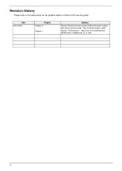
Revise " Performance " : Maximum of 512 MB Rambus DRAM within 4 RIMM slots up to the table below for the updates made on Veriton 9100 service guide. II Revision History Please refer to 1GB. Date 03/13/2001 Chapter Chapter 3 Chapter 1 Updates Revise "Remove the five screws holding the power supply", and add the picture under " Removing the power supply".
Revise " Performance " : Maximum of 512 MB Rambus DRAM within 4 RIMM slots up to the table below for the updates made on Veriton 9100 service guide. II Revision History Please refer to 1GB. Date 03/13/2001 Chapter Chapter 3 Chapter 1 Updates Revise "Remove the five screws holding the power supply", and add the picture under " Removing the power supply".
Veriton 9100 Service Guide
Page 7
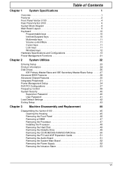
... System Specifications 1 Overview 1 Features 2 Front Panel-Veriton 9100 4 Rear Panel-Veriton 9100 6 System Block Diagram 8 Main Board Layout 9 Keyboard 10 Programmable keys 10 Internet/Suspend keys 10 Multimedia keys 11 Volume control/Mute 11 Cursor keys 11 Lock keys 11 Windows keys 12 Hardware Specifications and Configurations 13 Power Management Functions 21 Chapter 2 System Utilities...-RW Drive 50 Removing the PCI and AGP Expansion Cards 51 Removing the Audio Board 51 Removing the System Main Board 52 Removing the Power Supply 52 Removing the Intrusion Alarm 53 VII
... System Specifications 1 Overview 1 Features 2 Front Panel-Veriton 9100 4 Rear Panel-Veriton 9100 6 System Block Diagram 8 Main Board Layout 9 Keyboard 10 Programmable keys 10 Internet/Suspend keys 10 Multimedia keys 11 Volume control/Mute 11 Cursor keys 11 Lock keys 11 Windows keys 12 Hardware Specifications and Configurations 13 Power Management Functions 21 Chapter 2 System Utilities...-RW Drive 50 Removing the PCI and AGP Expansion Cards 51 Removing the Audio Board 51 Removing the System Main Board 52 Removing the Power Supply 52 Removing the Intrusion Alarm 53 VII

Veriton 9100 Service Guide
Page 15
Rear Panel-Veriton 9100 Label 1 2 Icon Color White Description Power cord socket Network port 3 Burgundy Parallel/printer port 4 Gold Game/MIDI port 5 CTR/LCD monitor port 6 Power supply 7 Green PS/2 mouse port 8 Purple PS/2 keyboard port 9 Teal or Turquoise Serial port 6 Chapter 1
Rear Panel-Veriton 9100 Label 1 2 Icon Color White Description Power cord socket Network port 3 Burgundy Parallel/printer port 4 Gold Game/MIDI port 5 CTR/LCD monitor port 6 Power supply 7 Green PS/2 mouse port 8 Purple PS/2 keyboard port 9 Teal or Turquoise Serial port 6 Chapter 1

Veriton 9100 Service Guide
Page 29
... VRMS 90-132 VRMS 180-264 VRMS Variation Range Input Current 10A / 9A* 5A / 4.5A* 90 -132 VRMS 180 - 264 VRMS (This is for 300 power supply) NOTE: * 9A & 4.5A are for Model : DPS-300 GB-1D Measuring Range Output Requirements +5V +12V -12V -5V +5VSBV +3.3V +-5% +-5% +-10% +-5% +-5% +-5% ...Regulation 30A 15A 0.8A 0.5A 2A 26A Current Rating(Max NOTE: 1. +3.3V and +5V total ouput power can't exceed 220W. 2. +3.3V, +5V & +12 total ouput power can't exceed 290W . 3. -12V and -5V combine current can't exceed 0.8A . 20 Chapter 1
... VRMS 90-132 VRMS 180-264 VRMS Variation Range Input Current 10A / 9A* 5A / 4.5A* 90 -132 VRMS 180 - 264 VRMS (This is for 300 power supply) NOTE: * 9A & 4.5A are for Model : DPS-300 GB-1D Measuring Range Output Requirements +5V +12V -12V -5V +5VSBV +3.3V +-5% +-5% +-10% +-5% +-5% +-5% ...Regulation 30A 15A 0.8A 0.5A 2A 26A Current Rating(Max NOTE: 1. +3.3V and +5V total ouput power can't exceed 220W. 2. +3.3V, +5V & +12 total ouput power can't exceed 290W . 3. -12V and -5V combine current can't exceed 0.8A . 20 Chapter 1

Veriton 9100 Service Guide
Page 61
Put the housing to lying position with the open area facing upward. 2. Chapter 3 52 Disconnect the power supply power connector from the housing. Remove the seven screws holding the power supply, and then remove the power supply from the housing.. Remove the five screws holding the main board and then remove the main board from the main board. 2. Removing the Power Supply 1. Removing the System Main Board 1.
Put the housing to lying position with the open area facing upward. 2. Chapter 3 52 Disconnect the power supply power connector from the housing. Remove the seven screws holding the power supply, and then remove the power supply from the housing.. Remove the five screws holding the main board and then remove the main board from the main board. 2. Removing the Power Supply 1. Removing the System Main Board 1.
Veriton 9100 Service Guide
Page 65
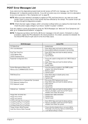
...Messages List If you cannot run a total system check to [Write Protected] in the Security Options in BIOS Setup. 2. Also check the power supply voltages if you did receive a POST error message, use "POST Error Messages List" to "Undetermined Problems" on page 58. If no ... 2. Enter BIOS Setup and load the default settings. 2. System board. 1. System boar 1. If you replace the main board. NOTE: Check all power supply voltages, switch, and jumper settings before you are NOT factory- Enter BIOS Setup to a check procedure, replace the FRU indicated in BIOS Setup is ...
...Messages List If you cannot run a total system check to [Write Protected] in the Security Options in BIOS Setup. 2. Also check the power supply voltages if you did receive a POST error message, use "POST Error Messages List" to "Undetermined Problems" on page 58. If no ... 2. Enter BIOS Setup and load the default settings. 2. System board. 1. System boar 1. If you replace the main board. NOTE: Check all power supply voltages, switch, and jumper settings before you are NOT factory- Enter BIOS Setup to a check procedure, replace the FRU indicated in BIOS Setup is ...

Veriton 9100 Service Guide
Page 67
... default settings. See "Undetermined Problems". See "Undetermined Problems". 4. Error Symptoms List NOTE: To diagnose a problem, first find the error symptom in Power Management Property of Control Panel. 2. System works but power supply fan runs. 1. Execute a system test and set to None in BIOS Setup and its speed requirement before system boot. 1. Blinking cursor...
... default settings. See "Undetermined Problems". See "Undetermined Problems". 4. Error Symptoms List NOTE: To diagnose a problem, first find the error symptom in Power Management Property of Control Panel. 2. System works but power supply fan runs. 1. Execute a system test and set to None in BIOS Setup and its speed requirement before system boot. 1. Blinking cursor...

Veriton 9100 Service Guide
Page 70
... software from Windows98 Start menu does not turn off the system.) 1. System board. No system power, or power supply fan is properly installed. Error Symptom Action/FRU Parallel/Serial Ports Execute "Load BIOS Default Settings"...the printer driver is not running. 1. Ensure the Power Switch < 4 sec. Printer problems. 1. Load default settings. 2. Keyboard Power Supply Pressing power switch does not turn off system. (Only unplugging the power cord from electrical outlet can turn off the system). 1. Power Supply 2. Printer. 3. Loop-back. 3. Make sure...
... software from Windows98 Start menu does not turn off the system.) 1. System board. No system power, or power supply fan is properly installed. Error Symptom Action/FRU Parallel/Serial Ports Execute "Load BIOS Default Settings"...the printer driver is not running. 1. Ensure the Power Switch < 4 sec. Printer problems. 1. Load default settings. 2. Keyboard Power Supply Pressing power switch does not turn off system. (Only unplugging the power cord from electrical outlet can turn off the system). 1. Power Supply 2. Printer. 3. Loop-back. 3. Make sure...
Veriton 9100 Service Guide
Page 71
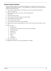
...List" on the system unit. 12. Any adapter card (modem card, LAN card or video card, if installed) ! Processor ! Check the power supply voltages. Non-Acer devices ! Repeat steps 2 through 5 until you did not receive any messages, see if the symptom is present, go to "POST Error Messages ...or disconnect the following checks, one by one at a time: 10. CD/DVD-ROM drive ! Power on page 58. DIMM ! Undetermined Problems If an error message is listed in setup. 5. Power off the system unit. 3. If the jumpers, switches and voltage settings are correct continue with this ...
...List" on the system unit. 12. Any adapter card (modem card, LAN card or video card, if installed) ! Processor ! Check the power supply voltages. Non-Acer devices ! Repeat steps 2 through 5 until you did not receive any messages, see if the symptom is present, go to "POST Error Messages ...or disconnect the following checks, one by one at a time: 10. CD/DVD-ROM drive ! Power on page 58. DIMM ! Undetermined Problems If an error message is listed in setup. 5. Power off the system unit. 3. If the jumpers, switches and voltage settings are correct continue with this ...
Veriton 9100 Service Guide
Page 94
.../printer port 11 Password setting 45 PCI removing 56 PCI INTx# 22 PCI Slot IRQ 22 ports left panel 11 POST 60 Power button 9 Power LED 9 Power Management 25, 39 Power Supply removing 57 Power-On Self-Test (POST) 60 Processor 52, 53 removing 52, 53 Product Information 29 DMI BIOS version 29 main board ID...
.../printer port 11 Password setting 45 PCI removing 56 PCI INTx# 22 PCI Slot IRQ 22 ports left panel 11 POST 60 Power button 9 Power LED 9 Power Management 25, 39 Power Supply removing 57 Power-On Self-Test (POST) 60 Processor 52, 53 removing 52, 53 Product Information 29 DMI BIOS version 29 main board ID...

Veriton 9100 Service Guide
Page 95
...List 63 Audio 65 CD/DVD-ROM Drive 64 Diskette Drive 63 Keyboard 66 Memory 63 Modem 65 Monitor 65 Other 66 Parallel Port 66 Power Supply 66 Processor / Processor Fan 63 Real-Time Clock 65 Serial Port 66 System Board 63 Video 65 System 27 System Board removing 57 ...System Memory 52 System Specifications 6 design 8 Features 7 System Utilities 27 Disk Drives 30 Exiting Setup 48 Load Default Settings 47 Power Management 39 Product Information 29 System Security 45 T Temperature 24 Test Compatible Components 83 Troubleshooting 59 U UART 21 Undetermined Problems 67 USB Port 21 ...
...List 63 Audio 65 CD/DVD-ROM Drive 64 Diskette Drive 63 Keyboard 66 Memory 63 Modem 65 Monitor 65 Other 66 Parallel Port 66 Power Supply 66 Processor / Processor Fan 63 Real-Time Clock 65 Serial Port 66 System Board 63 Video 65 System 27 System Board removing 57 ...System Memory 52 System Specifications 6 design 8 Features 7 System Utilities 27 Disk Drives 30 Exiting Setup 48 Load Default Settings 47 Power Management 39 Product Information 29 System Security 45 T Temperature 24 Test Compatible Components 83 Troubleshooting 59 U UART 21 Undetermined Problems 67 USB Port 21 ...


