

Veriton 7200
Page 5
...service. 12. If the product has been dropped or the cabinet has been damaged f. Refer battery replacement to rain or water d. When the power cord or plug is 15 feet (4.6 meters). Replace the battery with this product through cabinet slots as the product's battery we recommend. Batteries may...may explode if not handled properly. v 8. Use only the proper type of any kind on the product. 10. Never push objects of power supply cord set (provided in damage and will often require extensive work by the operating instructions since improper adjustment of used with the same type ...
...service. 12. If the product has been dropped or the cabinet has been damaged f. Refer battery replacement to rain or water d. When the power cord or plug is 15 feet (4.6 meters). Replace the battery with this product through cabinet slots as the product's battery we recommend. Batteries may...may explode if not handled properly. v 8. Use only the proper type of any kind on the product. 10. Never push objects of power supply cord set (provided in damage and will often require extensive work by the operating instructions since improper adjustment of used with the same type ...

Veriton 7200
Page 22
12 Rear panel Your computer's rear panel consists of the following: 2 System tour Label Icon 1 2 3 4 5 6 7 8 9 Color White Component Power switch Voltage selector switch Power cord socket Network port Burgundy Parallel/Printer port Gold Game/MIDI port Green CRT/LCD monitor port Power supply PS/2 mouse port
12 Rear panel Your computer's rear panel consists of the following: 2 System tour Label Icon 1 2 3 4 5 6 7 8 9 Color White Component Power switch Voltage selector switch Power cord socket Network port Burgundy Parallel/Printer port Gold Game/MIDI port Green CRT/LCD monitor port Power supply PS/2 mouse port

Veriton 7200
Page 58
Component 1 5.25-inch drive bays (three bays) 2 3.5-inch drive bays (two bays) 3 Daughterboard 4 Mainboard 5 Hard disk 6 Expansion slots 7 Power supply 48 4 Upgrading your computer Internal components The figure below shows what your computer looks like once you remove the cover: No.
Component 1 5.25-inch drive bays (three bays) 2 3.5-inch drive bays (two bays) 3 Daughterboard 4 Mainboard 5 Hard disk 6 Expansion slots 7 Power supply 48 4 Upgrading your computer Internal components The figure below shows what your computer looks like once you remove the cover: No.
Veriton 7200 Service Guide
Page 5
Table of Contents Chapter 1 System Specifications 1 Overview 1 Features 2 Front Panel-Veriron 7200 4 Rear Panel-Veriton 7200 6 System Block Diagram 8 Main Board Layout 9 Keyboard 11 Hardware Specifications and Configurations 13 Power Management Functions 21 Chapter 2 System Utilities 22 Entering Setup 23 Product Information 24 Standard CMOS Features 25 ... the AGP VGA Card 59 Removing the Modem Card 59 Removing the Main Board 60 Removing the Power Supply 60 Removing the Intrusion Alarm 60 Removing the Processor 61 Removing a DIMM 62 Removing the RTC Battery 62 V
Table of Contents Chapter 1 System Specifications 1 Overview 1 Features 2 Front Panel-Veriron 7200 4 Rear Panel-Veriton 7200 6 System Block Diagram 8 Main Board Layout 9 Keyboard 11 Hardware Specifications and Configurations 13 Power Management Functions 21 Chapter 2 System Utilities 22 Entering Setup 23 Product Information 24 Standard CMOS Features 25 ... the AGP VGA Card 59 Removing the Modem Card 59 Removing the Main Board 60 Removing the Power Supply 60 Removing the Intrusion Alarm 60 Removing the Processor 61 Removing a DIMM 62 Removing the RTC Battery 62 V

Veriton 7200 Service Guide
Page 13
Rear Panel-Veriton 7200 Label 1 2 3 4 5 6 7 8 9 Icon Color White Description Power Switch Voltage Selector Switch (some) Power cord socket Network port Burgundy Parallel/printer port Gold Game/MIDI port Green CRT/LCD monitor port* Power supply PS/2 mouse port 6 Chapter 1
Rear Panel-Veriton 7200 Label 1 2 3 4 5 6 7 8 9 Icon Color White Description Power Switch Voltage Selector Switch (some) Power cord socket Network port Burgundy Parallel/printer port Gold Game/MIDI port Green CRT/LCD monitor port* Power supply PS/2 mouse port 6 Chapter 1
Veriton 7200 Service Guide
Page 27
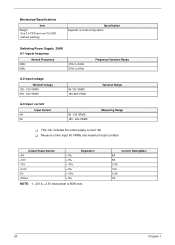
...: 2A ! Mechanical Specifications Item Weight One 3.5 FDD and one 3.5 HDD (without packing) Specification Depends on local configuration Switching Power Supply 200W A-1 Inpute frequency 50Hz 60Hz Normal Frequency 47Hz to 53Hz 57Hz to 63Hz Frequency Variation Range A-2 Input voltage Nominal Voltage 100 - 120 VRMS 200 - 240 ...
...: 2A ! Mechanical Specifications Item Weight One 3.5 FDD and one 3.5 HDD (without packing) Specification Depends on local configuration Switching Power Supply 200W A-1 Inpute frequency 50Hz 60Hz Normal Frequency 47Hz to 53Hz 57Hz to 63Hz Frequency Variation Range A-2 Input voltage Nominal Voltage 100 - 120 VRMS 200 - 240 ...

Veriton 7200 Service Guide
Page 60
Main unit Left Panel Right Panel Front Panel FDD Module HDD Module USB/Audio Board CD-ROM/ DVD-ROM AGP VGA Card Modem Board Main board Power Supply Intrusion Alarm Cable CPU Fan Sink DIMM CPU RTC Battery 53 Chapter 3 Disassembly Procedure Flowchart The flowchart on the succeeding page gives you a graphical representation on the entire disassembly sequence and instructs you on the components that need to be removed during servicing.
Main unit Left Panel Right Panel Front Panel FDD Module HDD Module USB/Audio Board CD-ROM/ DVD-ROM AGP VGA Card Modem Board Main board Power Supply Intrusion Alarm Cable CPU Fan Sink DIMM CPU RTC Battery 53 Chapter 3 Disassembly Procedure Flowchart The flowchart on the succeeding page gives you a graphical representation on the entire disassembly sequence and instructs you on the components that need to be removed during servicing.

Veriton 7200 Service Guide
Page 67
... 54. (Remove the left panel only) 2. Removing the Intrusion Alarm 1. See "Removing the Housing" on page 59 5. Disconnect the power supply power connector from the housing. Remove the screw that secures the intrusion alarm and then remove it from the main board. 3. Remove the four... See "Removing the Housing" on page 59 4. Removing the Power Supply 1. See "Removing the AGP VGA Card" on page 54. (Remove the left panel only) 2. Remove the six screws holding the power supply, and then remove the power supply from the housing. See "Removing the Housing" on page 54...
... 54. (Remove the left panel only) 2. Removing the Intrusion Alarm 1. See "Removing the Housing" on page 59 5. Disconnect the power supply power connector from the housing. Remove the screw that secures the intrusion alarm and then remove it from the main board. 3. Remove the four... See "Removing the Housing" on page 59 4. Removing the Power Supply 1. See "Removing the AGP VGA Card" on page 54. (Remove the left panel only) 2. Remove the six screws holding the power supply, and then remove the power supply from the housing. See "Removing the Housing" on page 54...
Veriton 7200 Service Guide
Page 78
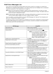
Also check the power supply voltages if you replace the main board. To diagnose a problem, first find the BIOS... bad memory chips. Make sure the controller is selected in the left column. If directed to ensure that no -power" condition. Also check if any error message, look for the new display type/ Be sure the adapter is attached... check can be replaced Check the battery and replace if necessary. Make sure the keyboard is installed correctly and all power supply voltages, switch, and jumper settings before you have done so, you assumed the system would boot from the hard...
Also check the power supply voltages if you replace the main board. To diagnose a problem, first find the BIOS... bad memory chips. Make sure the controller is selected in the left column. If directed to ensure that no -power" condition. Also check if any error message, look for the new display type/ Be sure the adapter is attached... check can be replaced Check the battery and replace if necessary. Make sure the keyboard is installed correctly and all power supply voltages, switch, and jumper settings before you have done so, you assumed the system would boot from the hard...

Veriton 7200 Service Guide
Page 80
... should be +12Vdc. Main board. System works but fails to enter power saving mode when the Power Management Mode is not set to Write protect in Power Management Property of processor fan connector. Main board. 73 Chapter 4 If the reading shows normal, but power supply fan runs. 1. Processor. 2. See "Memory" 2. In Windows Systems, check settings...
... should be +12Vdc. Main board. System works but fails to enter power saving mode when the Power Management Mode is not set to Write protect in Power Management Property of processor fan connector. Main board. 73 Chapter 4 If the reading shows normal, but power supply fan runs. 1. Processor. 2. See "Memory" 2. In Windows Systems, check settings...

Veriton 7200 Service Guide
Page 83
...ports problems. Serial or parallel port loop-back test failed. 1. Ensure the Power Switch < 4 sec. No system power, or power supply fan is properly installed. Printing failed. 1. Printer cable. 4. Main board. Power switch cable assembly. Main board Other Problems Any other problems. 1. Keyboard ...Some or all keys on the system. 1. Main board. Power switch cable assembly Pressing power switch does not turn off the system.) 1. Reload software from electrical outlet can turn off . 2. Power Supply 2. Make sure that the LPT# or COM# you test is ...
...ports problems. Serial or parallel port loop-back test failed. 1. Ensure the Power Switch < 4 sec. No system power, or power supply fan is properly installed. Printing failed. 1. Printer cable. 4. Main board. Power switch cable assembly. Main board Other Problems Any other problems. 1. Keyboard ...Some or all keys on the system. 1. Main board. Power switch cable assembly Pressing power switch does not turn off the system.) 1. Reload software from electrical outlet can turn off . 2. Power Supply 2. Make sure that the LPT# or COM# you test is ...

Veriton 7200 Service Guide
Page 84
... settings. 6. CD/DVD-ROM drive ! DIMM ! Check the power supply voltages. Load default settings in "or "Error Symptoms List" on the system unit. 12. Diskette drive ! Power on page 73 . Check all device jumper positions. 8. Check... all cables and connectors for proper installation. 9. Check all adapter card jumper positions. 7. Undetermined Problems If an error message is listed in setup. 5. If the voltages are correct, remove or disconnect the following checks, one by one at a time: 10. Non-Acer...
... settings. 6. CD/DVD-ROM drive ! DIMM ! Check the power supply voltages. Load default settings in "or "Error Symptoms List" on the system unit. 12. Diskette drive ! Power on page 73 . Check all device jumper positions. 8. Check... all cables and connectors for proper installation. 9. Check all adapter card jumper positions. 7. Undetermined Problems If an error message is listed in setup. 5. If the voltages are correct, remove or disconnect the following checks, one by one at a time: 10. Non-Acer...
Veriton 7200 Service Guide
Page 108
... Port 16 Parallel/printer port 6 Password bypassing 42 setting 40 PCI INTx# 17 PCI Slot IRQ 17 ports left panel 6 POST 65 Power button 4 Power LED 4 Power Management 20, 34 Power-On Self-Test (POST) 65 Processor 61 removing 61 Product Information 24 DMI BIOS version 24 main board ID 24 product name 24... RIMM Removing 60 RMA 80 Routing Map 17 S Security 40 Serial Port 16 Serial port 7 socket memory 14 Socket 370 13 Suspend Mode 21 Switching Power Supply 102W 20 Symptoms List Audio 75 Index
... Port 16 Parallel/printer port 6 Password bypassing 42 setting 40 PCI INTx# 17 PCI Slot IRQ 17 ports left panel 6 POST 65 Power button 4 Power LED 4 Power Management 20, 34 Power-On Self-Test (POST) 65 Processor 61 removing 61 Product Information 24 DMI BIOS version 24 main board ID 24 product name 24... RIMM Removing 60 RMA 80 Routing Map 17 S Security 40 Serial Port 16 Serial port 7 socket memory 14 Socket 370 13 Suspend Mode 21 Switching Power Supply 102W 20 Symptoms List Audio 75 Index
Veriton 7200 Service Guide
Page 109
CD/DVD-ROM Drive 74 Diskette Drive 73 Keyboard 76 Memory 73 Modem 75 Monitor 75 Other 76 Parallel Port 76 Power Supply 76 Processor / Processor Fan 73 Real-Time Clock 74 Serial Port 76 System Board 73 Video 75 System 22 System Board removing 60 System Memory... 60 System Specifications 1, 87 design 3 Features 2, 88 System Utilities 22 Disk Drives 25 Exiting Setup 44 Load Default Settings 43 Power Management 34 Product Information 24 System Security 40 T Temperature 19 Test Compatible Components 90 Troubleshooting 64 U UART 16 Undetermined Problems 77 USB Port 16 USB...
CD/DVD-ROM Drive 74 Diskette Drive 73 Keyboard 76 Memory 73 Modem 75 Monitor 75 Other 76 Parallel Port 76 Power Supply 76 Processor / Processor Fan 73 Real-Time Clock 74 Serial Port 76 System Board 73 Video 75 System 22 System Board removing 60 System Memory... 60 System Specifications 1, 87 design 3 Features 2, 88 System Utilities 22 Disk Drives 25 Exiting Setup 44 Load Default Settings 43 Power Management 34 Product Information 24 System Security 40 T Temperature 19 Test Compatible Components 90 Troubleshooting 64 U UART 16 Undetermined Problems 77 USB Port 16 USB...


