Service Guide
Page 3
..., a part number change is made, it supports, please read the following conventions are used in this printed Service Guide. In such cases, please contact your regional Acer office to those given in the FRU list of this manual: Screen messages Denotes actual messages that appear on card, modem, or extra memory capability). Caution Gives precautionary measures to avoid possible hardware or software problems...
..., a part number change is made, it supports, please read the following conventions are used in this printed Service Guide. In such cases, please contact your regional Acer office to those given in the FRU list of this manual: Screen messages Denotes actual messages that appear on card, modem, or extra memory capability). Caution Gives precautionary measures to avoid possible hardware or software problems...
Service Guide
Page 4
...frequency energy, and if not installed and used in accordance with the limits for energy efficiency. You are cautioned that changes or modifications not expressly approved by the party responsible for help. Do not open the cabinet. These limits are present inside the monitor... installation. WARNING: (FOR FCC CERTIFIED MODELS) NOTE: this equipment has been tested and found to comply with the instructions, may cause harmful interference to radio communications. Warning Use only shielded signal cables to connect I/O devices to qualified personnel only. - 4 - Refer servicing to...
...frequency energy, and if not installed and used in accordance with the limits for energy efficiency. You are cautioned that changes or modifications not expressly approved by the party responsible for help. Do not open the cabinet. These limits are present inside the monitor... installation. WARNING: (FOR FCC CERTIFIED MODELS) NOTE: this equipment has been tested and found to comply with the instructions, may cause harmful interference to radio communications. Warning Use only shielded signal cables to connect I/O devices to qualified personnel only. - 4 - Refer servicing to...

Service Guide
Page 5
... plug, a plug with the monitor. If you mount the monitor on the label. Do not place the monitor in a wet basement. If your dealer or local power company. Please refer all servicing to service the monitor yourself; PRECAUTIONS z Do not use the monitor near or over a radiator or heat register. Use only a trolley or stand recommended by the manufacture and follow the kit instructions. This plug...
... plug, a plug with the monitor. If you mount the monitor on the label. Do not place the monitor in a wet basement. If your dealer or local power company. Please refer all servicing to service the monitor yourself; PRECAUTIONS z Do not use the monitor near or over a radiator or heat register. Use only a trolley or stand recommended by the manufacture and follow the kit instructions. This plug...
Service Guide
Page 6
... Power Switch for hours. z You may remain after switching the image, when the same image is recovered slowly by changing the image or turning off the Power Switch and then turn it on the desktop pattern you use . In this case, the screen is displayed for hours. - 6 - z The LCD screen has effective pixels of the time. z Due to the nature of the previous screen may find slightly uneven brightness...
... Power Switch for hours. z You may remain after switching the image, when the same image is recovered slowly by changing the image or turning off the Power Switch and then turn it on the desktop pattern you use . In this case, the screen is displayed for hours. - 6 - z The LCD screen has effective pixels of the time. z Due to the nature of the previous screen may find slightly uneven brightness...

Service Guide
Page 7
... BLOCK DIAGRAM ...24 MONITOR BOARD LAYOUT ...25 SOFTWARE FLOW CHART ...27 GENERAL INSTRUCTIONS ...28 SYSTEM INSTALLATION ...29 POWER/INVERTOR BOARD ...34 ELECTRICAL SPECIFICATION...35 SAFETY ...37 Chapter 2 Operating Instruction 39 CONTROLS ...39 MAIN OSD MENU...40 OSD MESSAGE...42 PLUG AND PLAY ...44 WHITE COLOR TEMPERATURE...45 AUDIO TECHNICAL SPECIFICATION ...45 Chapter 3 Machine Disassembly and Replacement 47 DISASSEMBLY PROCEDURE ...47 Chapter 4 Troubleshooting 50 TROUBLESHOOTING ...54 Chapter 5 Connector Information 55 CONNECTOR INFORMATION ...58 Chapter 6 FRU List 59 PART...
... BLOCK DIAGRAM ...24 MONITOR BOARD LAYOUT ...25 SOFTWARE FLOW CHART ...27 GENERAL INSTRUCTIONS ...28 SYSTEM INSTALLATION ...29 POWER/INVERTOR BOARD ...34 ELECTRICAL SPECIFICATION...35 SAFETY ...37 Chapter 2 Operating Instruction 39 CONTROLS ...39 MAIN OSD MENU...40 OSD MESSAGE...42 PLUG AND PLAY ...44 WHITE COLOR TEMPERATURE...45 AUDIO TECHNICAL SPECIFICATION ...45 Chapter 3 Machine Disassembly and Replacement 47 DISASSEMBLY PROCEDURE ...47 Chapter 4 Troubleshooting 50 TROUBLESHOOTING ...54 Chapter 5 Connector Information 55 CONNECTOR INFORMATION ...58 Chapter 6 FRU List 59 PART...
Service Guide
Page 8
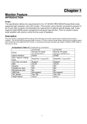
... oriented product with volume control to general 15 pin D-sub VGA connector and eliminates the requirement of AV698/699 & AV898/899 AV698/699 Panel Normal 19" panel AU-M190EN04(V5) Signal Interface DSUB Sync Type for the 19" MICRO-PROCESSOR based Multi-mode supported high resolution color LCD monitor. Monitor Feature INTRODUCTION Chapter 1 Scope This specification defines the requirements for analog input Separate / compatible / Color Temp user adjust Support DDC DDC2B Speaker NO Headphone Jack...
... oriented product with volume control to general 15 pin D-sub VGA connector and eliminates the requirement of AV698/699 & AV898/899 AV698/699 Panel Normal 19" panel AU-M190EN04(V5) Signal Interface DSUB Sync Type for the 19" MICRO-PROCESSOR based Multi-mode supported high resolution color LCD monitor. Monitor Feature INTRODUCTION Chapter 1 Scope This specification defines the requirements for analog input Separate / compatible / Color Temp user adjust Support DDC DDC2B Speaker NO Headphone Jack...
Service Guide
Page 9
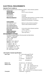
Minolta CA100 photometer, or equivalent Control settings User brightness control : Maximum (unless otherwise specified ) User contrast control: Typical (unless otherwise specified ) User red/white balance, Green/white balance and Blue/white balance control : In the center (unless otherwise specified ) Power input: 110Vac or 230Vac Ambient temperature: 20 ± 5 ˚C ( 68 ± 9 ˚ F) Analog input mode: 1280 x1024 /60 Hz MEASUREMENT SYSTEMS The units of measure stated in this document are listed below...
Minolta CA100 photometer, or equivalent Control settings User brightness control : Maximum (unless otherwise specified ) User contrast control: Typical (unless otherwise specified ) User red/white balance, Green/white balance and Blue/white balance control : In the center (unless otherwise specified ) Power input: 110Vac or 230Vac Ambient temperature: 20 ± 5 ˚C ( 68 ± 9 ˚ F) Analog input mode: 1280 x1024 /60 Hz MEASUREMENT SYSTEMS The units of measure stated in this document are listed below...
Service Guide
Page 16
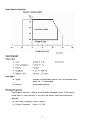
... the entered mode does not match the supported timing the display optimization will not be assured. • Horizontal Frequency 30KHz --80KHz • Vertical Frequency 49Hz -------75Hz - 16 - Panel Relative Humidity Input Signals Video input • Type • Input Impedance • Polarity • Amplitude • Display Color Sync input • Signal • Polarity JP777-E02 Analog R, G, B. 75 ohm +/- 2% Positive 0 - 0.7 +/- 0.05 Vp same as LCD panel DVI (option) separate horizontal and vertical sync, or composite sync which are TTL compatible positive and...
... the entered mode does not match the supported timing the display optimization will not be assured. • Horizontal Frequency 30KHz --80KHz • Vertical Frequency 49Hz -------75Hz - 16 - Panel Relative Humidity Input Signals Video input • Type • Input Impedance • Polarity • Amplitude • Display Color Sync input • Signal • Polarity JP777-E02 Analog R, G, B. 75 ohm +/- 2% Positive 0 - 0.7 +/- 0.05 Vp same as LCD panel DVI (option) separate horizontal and vertical sync, or composite sync which are TTL compatible positive and...

Service Guide
Page 24
By changing these settings, the picture can be connected. z Connect the video cable from the monitor to the video card. z Press the power button to turn the monitor on the monitor position. External Controls 1 LED 2 / Power Key 3 >/ Volume 4 z The power cord should be adjusted to your personal preferences. The power indicator will light up. General Instructions Press the power button to turn on or off. The other control buttons are located at front panel of the monitor.
By changing these settings, the picture can be connected. z Connect the video cable from the monitor to the video card. z Press the power button to turn the monitor on the monitor position. External Controls 1 LED 2 / Power Key 3 >/ Volume 4 z The power cord should be adjusted to your personal preferences. The power indicator will light up. General Instructions Press the power button to turn on or off. The other control buttons are located at front panel of the monitor.
Service Guide
Page 26
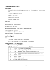
... specification defined the performance and characteristic of power/inverter board. Output Connector & Pin Assignment: 1. The connecter was pitch 2.0mm. AC Inlet: HUAJIE SA-4S-328 or compatible. 2. Features Input Voltage: 100 ~ 240 ±10%Vac Input Frequency: 47 ~ 63Hz Input power consumption: Less than 1W @ minimum load Total output power: 40Wmax Inverter brightness adjustment: Burst mode Protection function: auto-recovery type Interface Signals Input 1. PIN NO. It supplies...
... specification defined the performance and characteristic of power/inverter board. Output Connector & Pin Assignment: 1. The connecter was pitch 2.0mm. AC Inlet: HUAJIE SA-4S-328 or compatible. 2. Features Input Voltage: 100 ~ 240 ±10%Vac Input Frequency: 47 ~ 63Hz Input power consumption: Less than 1W @ minimum load Total output power: 40Wmax Inverter brightness adjustment: Burst mode Protection function: auto-recovery type Interface Signals Input 1. PIN NO. It supplies...
Service Guide
Page 27
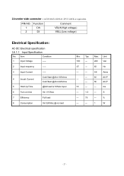
2.Inverter-side connecter : ACES 88451-020N-01 2P3.5 LOCK or equivalent. Function 1 Cth 2 Ctl Comment VBLH(High voltage) VBLL(Low voltage) Electrical Specification: AC-DC Electrical specification 3.4.1.1 Input Specification No Item Condition 1 Input Voltage ----- 2 Input requency ----- 3 Input Current 4 Inrush Current 5 Hold Up Time ----Cold Start @Vin=100Vrms Cold Start @Vin=240Vrms @full load & 100Vac input 6 Turn on time Vin =110Vac 7 Efficiency Full load 8 Consumption...
2.Inverter-side connecter : ACES 88451-020N-01 2P3.5 LOCK or equivalent. Function 1 Cth 2 Ctl Comment VBLH(High voltage) VBLL(Low voltage) Electrical Specification: AC-DC Electrical specification 3.4.1.1 Input Specification No Item Condition 1 Input Voltage ----- 2 Input requency ----- 3 Input Current 4 Inrush Current 5 Hold Up Time ----Cold Start @Vin=100Vrms Cold Start @Vin=240Vrms @full load & 100Vac input 6 Turn on time Vin =110Vac 7 Efficiency Full load 8 Consumption...
Service Guide
Page 28
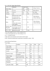
... Load load change of Over / Under @ Power line on both outputs 2) OPP: Should be acted on /off --- ±10% --- Input Voltage ---...Brightness lamp current in 7mA 250 Output Current(Each Vbri=0.4V~3.3V 4 connector) Frequency --- 40 Lamp start voltage @0℃ 1650 - 28 - Typ. 19 1.5 3.3 0 30% 650 300 7.5 ----- Input Current --- --- Max. ----- ------8 60 --- Backlight ON/OFF Control ON OFF Brightness Adjust...power consumption is limited +5Vdc:150mVp-p +19Vinv:570mVp-p within ~ 55W Inverter Electrical Specification: For 19" Panel Condition Min.
... Load load change of Over / Under @ Power line on both outputs 2) OPP: Should be acted on /off --- ±10% --- Input Voltage ---...Brightness lamp current in 7mA 250 Output Current(Each Vbri=0.4V~3.3V 4 connector) Frequency --- 40 Lamp start voltage @0℃ 1650 - 28 - Typ. 19 1.5 3.3 0 30% 650 300 7.5 ----- Input Current --- --- Max. ----- ------8 60 --- Backlight ON/OFF Control ON OFF Brightness Adjust...power consumption is limited +5Vdc:150mVp-p +19Vinv:570mVp-p within ~ 55W Inverter Electrical Specification: For 19" Panel Condition Min.
Service Guide
Page 30
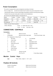
...-state to any power saving state to another can be instantaneous. Mode H-Sync. Power : Monitor rear side : AC Inlet - Audio : Monitor rear side : -PC I/P for PC : 3.5mm Stereo female Monitor Control Keys KEY : Power , Menu , Adjust +/- , Vol +/-, Auto Position Of Controls Position of all switches Position of LED : Bottom side of front bezel : Bottom side of 15-pin D-sub: 1 Red Video 9 +5V FOR DDC 2 Green Video 10 Detect 3 Blue Video 11 Serial Data for ISP 4 Serial Clock for...
...-state to any power saving state to another can be instantaneous. Mode H-Sync. Power : Monitor rear side : AC Inlet - Audio : Monitor rear side : -PC I/P for PC : 3.5mm Stereo female Monitor Control Keys KEY : Power , Menu , Adjust +/- , Vol +/-, Auto Position Of Controls Position of all switches Position of LED : Bottom side of front bezel : Bottom side of 15-pin D-sub: 1 Red Video 9 +5V FOR DDC 2 Green Video 10 Detect 3 Blue Video 11 Serial Data for ISP 4 Serial Clock for...

Service Guide
Page 31
When OSD Menu is on; When into Factory mode press 3 (plus +) or 4 (minus -) at the same time can activate "Auto Adjustment" immediately. 3. be blue when monitor is off, press button 6 (auto) at the same time can activate "Volume Adjustment". 2. Press button 3 (plus +) ,4 (minus -) and 2 (power) together 2 seconds at same time. - 31 - Chapter 2 Operating Instructions CONTROLS Control panel (monitor front panel) 1 Power LED, will be amber when in power saving mode. 2 Power ON/OFF switch, push to ON and...
When OSD Menu is on; When into Factory mode press 3 (plus +) or 4 (minus -) at the same time can activate "Auto Adjustment" immediately. 3. be blue when monitor is off, press button 6 (auto) at the same time can activate "Volume Adjustment". 2. Press button 3 (plus +) ,4 (minus -) and 2 (power) together 2 seconds at same time. - 31 - Chapter 2 Operating Instructions CONTROLS Control panel (monitor front panel) 1 Power LED, will be amber when in power saving mode. 2 Power ON/OFF switch, push to ON and...
Service Guide
Page 33
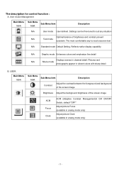
Acer eColor Management Main Menu icon Sub Menu Sub Menu item icon Description N/A User mode User defined. The most comfortable way to suit any situation Optimal balance of the screen image ACM Focus Clock ACM (Adaptive Contrast Management)A CM ON/OFF Switch, default "OFF" Adjust picture Focus (available in analog mode only) Adjust picture Clock (available in vibrant colors with sharp detail B. Settings can be fine-tuned to read onscreen text N/A Standard mode Default Setting. USER. The...
Acer eColor Management Main Menu icon Sub Menu Sub Menu item icon Description N/A User mode User defined. The most comfortable way to suit any situation Optimal balance of the screen image ACM Focus Clock ACM (Adaptive Contrast Management)A CM ON/OFF Switch, default "OFF" Adjust picture Focus (available in analog mode only) Adjust picture Clock (available in vibrant colors with sharp detail B. Settings can be fine-tuned to read onscreen text N/A Standard mode Default Setting. USER. The...
Service Guide
Page 34
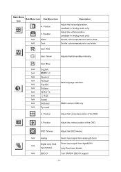
... OSD only Adjust the horizontal position of the OSD. N/A Analog Select input signal from analog (D-Sub) Digital (only Dual Select input signal from digital(DVI) N/A Input Model) (only Dual-Input Model) N/A DDC/CI Turn ON/OFF DDC/CI support - 34 - Position N/A Warm N/A Cool Description Adjust the horizontal position. (available in Analog mode only) Adjust the vertical position. (available in Analog mode only) Set the color temperature to cool white. Position Adjust the vertical position of the OSD. Position Multi-language selection. V. OSD Timeout Adjust the OSD...
... OSD only Adjust the horizontal position of the OSD. N/A Analog Select input signal from analog (D-Sub) Digital (only Dual Select input signal from digital(DVI) N/A Input Model) (only Dual-Input Model) N/A DDC/CI Turn ON/OFF DDC/CI support - 34 - Position N/A Warm N/A Cool Description Adjust the horizontal position. (available in Analog mode only) Adjust the vertical position. (available in Analog mode only) Set the color temperature to cool white. Position Adjust the vertical position of the OSD. Position Multi-language selection. V. OSD Timeout Adjust the OSD...

Service Guide
Page 37
... the Hsync Frequency, Vsync Frequency or Resolution is no active signal input, will show this message. Hot-Key Function OSD Message: Outline: The description for Hot-Key function : Item Operation Icon Description Adjustment Reset Range Value Volume When the OSD is not connected, will be flying. When the video cable is closed, press Volume of the monitor support range, will show this message, then enter power saving. - 37 - Audio Volume control:(option) Outline...
... the Hsync Frequency, Vsync Frequency or Resolution is no active signal input, will show this message. Hot-Key Function OSD Message: Outline: The description for Hot-Key function : Item Operation Icon Description Adjustment Reset Range Value Volume When the OSD is not connected, will be flying. When the video cable is closed, press Volume of the monitor support range, will show this message, then enter power saving. - 37 - Audio Volume control:(option) Outline...

Service Guide
Page 39
... a bidirectional data channel based on the level of a minimum No. 18 AWG, type SJT or SVT three conductors flexible cord. THIS MONITOR WILL APPEAR TO BE NON-FUNCTIONAL IF THERE IS NO VIDEO INPUT SIGNAL. This reduces the monitor's internal power supply consumption. The appearance is no video-input signal present. The voltage rating for connection to a "Screen Saver" feature except the display is defined in...
... a bidirectional data channel based on the level of a minimum No. 18 AWG, type SJT or SVT three conductors flexible cord. THIS MONITOR WILL APPEAR TO BE NON-FUNCTIONAL IF THERE IS NO VIDEO INPUT SIGNAL. This reduces the monitor's internal power supply consumption. The appearance is no video-input signal present. The voltage rating for connection to a "Screen Saver" feature except the display is defined in...

Service Guide
Page 42
Press the "Function -"key, "Function +" key & "Power" key simultaneously and Factory Model is got into as below 42 Connect D-SUB cable and Power cord according to the graphic, and input power and signal 2. SOP for Factory Mode 1. Turn on the monitor by clicking the power key, and show the normal image 4.
Press the "Function -"key, "Function +" key & "Power" key simultaneously and Factory Model is got into as below 42 Connect D-SUB cable and Power cord according to the graphic, and input power and signal 2. SOP for Factory Mode 1. Turn on the monitor by clicking the power key, and show the normal image 4.

Service Guide
Page 43
Operation system & Connection a. VGA cable shall be connected to next page . 43 RS232 cable b. Click to ISP out port. 2. VGA cable, d. Turn on PC system a. Click the ISP driver program(port95nt.exe) b. Install ISP BD driver on the power of monitor. ISP tool, c. PC (Win XP), b. SOP for ISP (Firmware upgrade) 1.
Operation system & Connection a. VGA cable shall be connected to next page . 43 RS232 cable b. Click to ISP out port. 2. VGA cable, d. Turn on PC system a. Click the ISP driver program(port95nt.exe) b. Install ISP BD driver on the power of monitor. ISP tool, c. PC (Win XP), b. SOP for ISP (Firmware upgrade) 1.


