
TravelMate 4060 Service Guide
Page 2
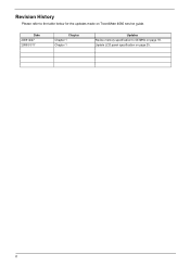
II Revision History Please refer to 533MHz on page 19. Date 200512/27 2006/01/17 Chapter Chapter 1 Chapter 1 Updates Revise memory specification to the table below for the updates made on page 25. Update LCD panel specification on TravelMate 4060 service guide.
II Revision History Please refer to 533MHz on page 19. Date 200512/27 2006/01/17 Chapter Chapter 1 Chapter 1 Updates Revise memory specification to the table below for the updates made on page 25. Update LCD panel specification on TravelMate 4060 service guide.
TravelMate 4060 Service Guide
Page 5
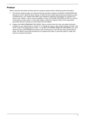
... offering. If, for repair and service of this printed Service Guide. You MUST use the list provided by your Acer office may have decided to -date information available on card, modem, or extra memory capability). To better fit local market requirements and enhance product competitiveness, your regional office MAY have a DIFFERENT part...
... offering. If, for repair and service of this printed Service Guide. You MUST use the list provided by your Acer office may have decided to -date information available on card, modem, or extra memory capability). To better fit local market requirements and enhance product competitiveness, your regional office MAY have a DIFFERENT part...
TravelMate 4060 Service Guide
Page 7
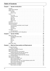
... Module 47 Disassembling the Hard Disc Drive Module 47 Removing the Optical Disc Drive Module 48 Disassembling the Optical Disc Drive Module 48 Removing the Memory 49 Removing the LCD Module 50 Removing the Middle Cover 50 Removing the Keyboard 50 Removing the Fan, the CPU Thermal Module and the CPU...
... Module 47 Disassembling the Hard Disc Drive Module 47 Removing the Optical Disc Drive Module 48 Disassembling the Optical Disc Drive Module 48 Removing the Memory 49 Removing the LCD Module 50 Removing the Middle Cover 50 Removing the Keyboard 50 Removing the Fan, the CPU Thermal Module and the CPU...
TravelMate 4060 Service Guide
Page 8
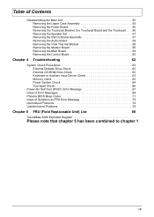
... 63 Memory check 64 Power System Check 64 Touchpad Check 66 Power-On Self-Test (POST) Error Message 67 Index of Error Messages 68 Phoenix BIOS Beep Codes 71 Index of Symptom-to-FRU Error Message 75 Intermittent Problems 78 Undetermined Problems 79 Chapter 6 FRU (Field Replaceable Unit) List 80 TravelMate 4060 Exploded...
... 63 Memory check 64 Power System Check 64 Touchpad Check 66 Power-On Self-Test (POST) Error Message 67 Index of Error Messages 68 Phoenix BIOS Beep Codes 71 Index of Symptom-to-FRU Error Message 75 Intermittent Problems 78 Undetermined Problems 79 Chapter 6 FRU (Field Replaceable Unit) List 80 TravelMate 4060 Exploded...
TravelMate 4060 Service Guide
Page 10
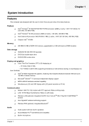
... Hz Communication T Modem: 56K ITU V.92 modem with PTT approval; Wake-on dual displays via Acer GridVista T Intel® 915GM integrated 3D graphics, featuring Intel Graphics Media Accelerator 900 and up to 128 MB of DDRII 533 memory, upgradeable to 2 GB with dual so DIMM modules Data storage T 40/60/80/100...
... Hz Communication T Modem: 56K ITU V.92 modem with PTT approval; Wake-on dual displays via Acer GridVista T Intel® 915GM integrated 3D graphics, featuring Intel Graphics Media Accelerator 900 and up to 128 MB of DDRII 533 memory, upgradeable to 2 GB with dual so DIMM modules Data storage T 40/60/80/100...

TravelMate 4060 Service Guide
Page 15
21 CN20 USB Connector 23 U19 BIOS ROM 25 CN22 RTC Battery 27 U1 LAN Chipset RTL8100CL 29 U18 South Bridge 31 CN25 HDD Connector 33 CN28 Line-out/SPEDIF Jack 35 CN30 Line-in Jack 37 SW2 Bluetooth Button 39 LED1 Power LED 41 U10 Fan Connector 22 CN21 USB Connector 24 U4 EC PC97551 (Power and I/O Connector) 26 CN18 Memory Socket 1 28 CN19 Memory Socket 2 30 CN24 PCMCIA Connector 32 CN27 USB Connector 34 CN29 Microphone Jack 36 SW3 WLAN Button 38 LED2 Charger LED 40 U22 Audio Codec 6 TravelMate 4060
21 CN20 USB Connector 23 U19 BIOS ROM 25 CN22 RTC Battery 27 U1 LAN Chipset RTL8100CL 29 U18 South Bridge 31 CN25 HDD Connector 33 CN28 Line-out/SPEDIF Jack 35 CN30 Line-in Jack 37 SW2 Bluetooth Button 39 LED1 Power LED 41 U10 Fan Connector 22 CN21 USB Connector 24 U4 EC PC97551 (Power and I/O Connector) 26 CN18 Memory Socket 1 28 CN19 Memory Socket 2 30 CN24 PCMCIA Connector 32 CN27 USB Connector 34 CN29 Microphone Jack 36 SW3 WLAN Button 38 LED2 Charger LED 40 U22 Audio Codec 6 TravelMate 4060

TravelMate 4060 Service Guide
Page 19
Unlatches the battery to a Kensington-compatible computer security lock. House the computer's main memory. 10 TravelMate 4060 Helps keep the computer cool. Security keylock Connects to remove the battery pack. Locks the battery in place. Houses the computer's battery pack. Note: Do ..., LCD projector). External display port Connects to an AC adaptor. Bottom view # 1 2 3 4 5 6 Item Hard disc bay Battery release latch Battery bay Battery lock Cooling fan Memory comparment Description Houses the computer's hard disc (secured by a screw).
Unlatches the battery to a Kensington-compatible computer security lock. House the computer's main memory. 10 TravelMate 4060 Helps keep the computer cool. Security keylock Connects to remove the battery pack. Locks the battery in place. Houses the computer's battery pack. Note: Do ..., LCD projector). External display port Connects to an AC adaptor. Bottom view # 1 2 3 4 5 6 Item Hard disc bay Battery release latch Battery bay Battery lock Cooling fan Memory comparment Description Houses the computer's hard disc (secured by a screw).
TravelMate 4060 Service Guide
Page 27
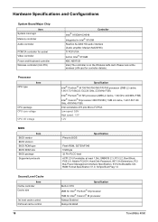
... ACPI 2.0 (if available, at the wireless LAN card for Intel® Celeron® M processor Always Enabled Always Enabled 18 TravelMate 4060 Hardware Specifications and Configurations System Board Major Chip Item System core logic Memory controller Audio controller PCMCIA controller for socket Video controller Power and Keyboard controller Wireless controller (mini PCI) Controller Intel...
... ACPI 2.0 (if available, at the wireless LAN card for Intel® Celeron® M processor Always Enabled Always Enabled 18 TravelMate 4060 Hardware Specifications and Configurations System Board Major Chip Item System core logic Memory controller Audio controller PCMCIA controller for socket Video controller Power and Keyboard controller Wireless controller (mini PCI) Controller Intel...
TravelMate 4060 Service Guide
Page 28
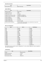
... Level Cache Item Cache scheme control System Memory Item Memory controller Onboard memory size DIMM socket number Supports memory size per socket Supports maximum memory size Supports DIMM type Supports DIMM Speed Supports DIMM voltage Supports DIMM package Memory module combinations Fixed-in write back Specification ...Specification built-in CPU 0MB 2 Sockets 256MB(min)/1024MB(max) 2GB with various capacities to form other combinations. Memory Combinations 0MB 0MB 0MB 256MB 256MB 256MB 256MB 512MB 512MB 512MB 512MB 1024MB 1024MB 1024MB 1024MB Slot 1 256MB 512MB 1024MB ...
... Level Cache Item Cache scheme control System Memory Item Memory controller Onboard memory size DIMM socket number Supports memory size per socket Supports maximum memory size Supports DIMM type Supports DIMM Speed Supports DIMM voltage Supports DIMM package Memory module combinations Fixed-in write back Specification ...Specification built-in CPU 0MB 2 Sockets 256MB(min)/1024MB(max) 2GB with various capacities to form other combinations. Memory Combinations 0MB 0MB 0MB 256MB 256MB 256MB 256MB 512MB 512MB 512MB 512MB 1024MB 1024MB 1024MB 1024MB Slot 1 256MB 512MB 1024MB ...
TravelMate 4060 Service Guide
Page 31
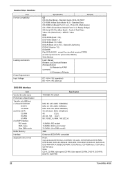
... discs, CD-R discs, CD-RW discs Write: CD-R, CD-RW, high-speed CD-RW, Ultra-speed CD-RW, DVD-R, DVD-RW, DVD+R, DVD+RW 22 TravelMate 4060 MPEG1 Video DVD DVD-ROM (Book 1.02), DVD-Video (Book 1.1) DVD-R (Book 1.0, 3.9G) DVD-R (Book 2.0, 4.7G) - Photo CD, Multi-Session CD-I /FMV (Green Book, Mode2.../sec) (1) Read DVD-ROM DVD-R CD-ROM (2) Write CD-R CD-RW HS-RW US-RW (3) ATAPI Interface PIO mode DMA mode Ultra DMA mode Buffer Memory Interface Applicable disc format Specification Remark CD CD-DA (Red Book) -
... discs, CD-R discs, CD-RW discs Write: CD-R, CD-RW, high-speed CD-RW, Ultra-speed CD-RW, DVD-R, DVD-RW, DVD+R, DVD+RW 22 TravelMate 4060 MPEG1 Video DVD DVD-ROM (Book 1.02), DVD-Video (Book 1.1) DVD-R (Book 1.0, 3.9G) DVD-R (Book 2.0, 4.7G) - Photo CD, Multi-Session CD-I /FMV (Green Book, Mode2.../sec) (1) Read DVD-ROM DVD-R CD-ROM (2) Write CD-R CD-RW HS-RW US-RW (3) ATAPI Interface PIO mode DMA mode Ultra DMA mode Buffer Memory Interface Applicable disc format Specification Remark CD CD-DA (Red Book) -
TravelMate 4060 Service Guide
Page 32
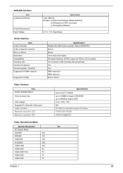
... PCM or AC-3 content 1Hz resolution VSR (Variable Sampling Rate) Yes Yes DMA channel 0 DMA channel 1 IRQ10, IRQ11 Video Interface Item Vendor & Model Name Video memory size Chip voltage Supports ZV (Zoomed Video) port Graph interface Maximum resolution LCD Maximum resolution CRT Specification built-in Stereo 18 bit stereo full duplex...
... PCM or AC-3 content 1Hz resolution VSR (Variable Sampling Rate) Yes Yes DMA channel 0 DMA channel 1 IRQ10, IRQ11 Video Interface Item Vendor & Model Name Video memory size Chip voltage Supports ZV (Zoomed Video) port Graph interface Maximum resolution LCD Maximum resolution CRT Specification built-in Stereo 18 bit stereo full duplex...
TravelMate 4060 Service Guide
Page 41
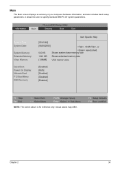
... The Main screen displays a summary of your computer hardware information, and also includes basic setup parameters. Shows system base memory size 1040 MB Shows extended memory size [128MB] VGA memory size [Enabled] [Both] [Enabled] [Disabled] [Enabled] F1 Help Esc Exit ↑ ↓ Select Item ... specify standard IBM PC AT system parameters. Information Main PhoenixBIOS Setup Utility Security Boot Exit System Time: System Date: System Memory: Extended Memory: Video Memory Quiet Boot: Power On Display: Network Boot F12 Boot Menu D2D Recovery Item Specific Help [05:45:48] [08/...
... The Main screen displays a summary of your computer hardware information, and also includes basic setup parameters. Shows system base memory size 1040 MB Shows extended memory size [128MB] VGA memory size [Enabled] [Both] [Enabled] [Disabled] [Enabled] F1 Help Esc Exit ↑ ↓ Select Item ... specify standard IBM PC AT system parameters. Information Main PhoenixBIOS Setup Utility Security Boot Exit System Time: System Date: System Memory: Extended Memory: Video Memory Quiet Boot: Power On Display: Network Boot F12 Boot Menu D2D Recovery Item Specific Help [05:45:48] [08/...
TravelMate 4060 Service Guide
Page 42
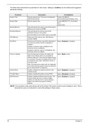
...Format/Option Sets the system time. The function allows the user to 640MB This field reports the memory size of the system. Extended Memory size=Total memory size-1MB Shows the VGA memory size. Disabled: Customer Logo is not displayed, and Summary Screen is disabled. Option: Enabled or ... is displayed, and Summary Screen is enabled. Option: Both or Auto Enables, disables the system boot from LAN (remote server). VGA Memory size=64/128MB Determines if Customer Logo will be displayed or not; Otherwise it will be in the system. Settings in these cases....
...Format/Option Sets the system time. The function allows the user to 640MB This field reports the memory size of the system. Extended Memory size=Total memory size-1MB Shows the VGA memory size. Disabled: Customer Logo is not displayed, and Summary Screen is disabled. Option: Enabled or ... is displayed, and Summary Screen is enabled. Option: Both or Auto Enables, disables the system boot from LAN (remote server). VGA Memory size=64/128MB Determines if Customer Logo will be displayed or not; Otherwise it will be in the system. Settings in these cases....
TravelMate 4060 Service Guide
Page 49
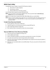
...and ESC key together for the following conditions: T New versions of this product to 5, you use the Phlash. BIOS Flash Utility The BIOS flash memory update is required for more than two seconds when you do not shut down the system or remove the power supply. 6. Copy BIOS.wph file...then you should create a Crisis Recovery Diskette before you can see the LCD screen with the backlight is not completely loaded. NOTE: Do not install memory-related drivers (XMS, EMS, DPMI) when you sould be able to three minutes, the system will read the files inside the floppy diskette without ...
...and ESC key together for the following conditions: T New versions of this product to 5, you use the Phlash. BIOS Flash Utility The BIOS flash memory update is required for more than two seconds when you do not shut down the system or remove the power supply. 6. Copy BIOS.wph file...then you should create a Crisis Recovery Diskette before you can see the LCD screen with the backlight is not completely loaded. NOTE: Do not install memory-related drivers (XMS, EMS, DPMI) when you sould be able to three minutes, the system will read the files inside the floppy diskette without ...
TravelMate 4060 Service Guide
Page 53
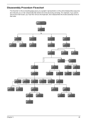
... frame in that need to remove the main board, you want to be removed during servicing. Start Battery HDD Module *2 HDD HDD Holder *2 Dimm Cover Memory *1 Modem Cover *2 Modem Board Hinge Caps *2 Middle Cover Keyboard *6 LCD Module *2 Launch Board Lower Case Assembly *2 FDD Module *3 *3 *11 *4 RTC Battery *3 Mini PCI Card Plate...
... frame in that need to remove the main board, you want to be removed during servicing. Start Battery HDD Module *2 HDD HDD Holder *2 Dimm Cover Memory *1 Modem Cover *2 Modem Board Hinge Caps *2 Middle Cover Keyboard *6 LCD Module *2 Launch Board Lower Case Assembly *2 FDD Module *3 *3 *11 *4 RTC Battery *3 Mini PCI Card Plate...
TravelMate 4060 Service Guide
Page 58
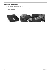
Removing the Memory 1. Pop out the memory. 4. Then remove the memory from the DIMM socket. 49 Chapter 3 Remove the two screws securing the DIMM cover then remove the DIMM cover. 3. See "Removing the Battery" on page 46. 2.
Removing the Memory 1. Pop out the memory. 4. Then remove the memory from the DIMM socket. 49 Chapter 3 Remove the two screws securing the DIMM cover then remove the DIMM cover. 3. See "Removing the Battery" on page 46. 2.
TravelMate 4060 Service Guide
Page 64
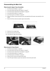
... assembly. 8. Removing the Power Board 1. See "Removing the Battery" on page 47. 3. See "Removing the Hard Disc Drive Module" on page 46. 2. See "Removing the Memory" on the bottom. 7. Remove the fifteen screws securing the lower case assembly and the upper case assembly on page 49. 5. Disassembling the Main Unit Removing... the LCD Module" on page 47. 3. See "Removing the Hard Disc Drive Module" on page 50. 6. Then detach the upper case assembly. See "Removing the Memory" on page 49. 5. Remove the two screws securing the power board. 7.
... assembly. 8. Removing the Power Board 1. See "Removing the Battery" on page 47. 3. See "Removing the Hard Disc Drive Module" on page 46. 2. See "Removing the Memory" on the bottom. 7. Remove the fifteen screws securing the lower case assembly and the upper case assembly on page 49. 5. Disassembling the Main Unit Removing... the LCD Module" on page 47. 3. See "Removing the Hard Disc Drive Module" on page 50. 6. Then detach the upper case assembly. See "Removing the Memory" on page 49. 5. Remove the two screws securing the power board. 7.
TravelMate 4060 Service Guide
Page 73
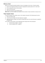
... pack; Follow the instructions in the following power sources: 1. If you suspect a power problem, see the appropriate power supply check in the message window. Memory check Memory errors might stop system operations, show error messages on the computer using each of the problem, power on the screen, or hang the system. 1. NOTE... test items. 3. Remove the battery pack. 2. Go to main board. 2. Boot from the diagnostics diskette and start the doagmpstotics program (please refer to the diagnostic memory in the test items. 4.
... pack; Follow the instructions in the following power sources: 1. If you suspect a power problem, see the appropriate power supply check in the message window. Memory check Memory errors might stop system operations, show error messages on the computer using each of the problem, power on the screen, or hang the system. 1. NOTE... test items. 3. Remove the battery pack. 2. Go to main board. 2. Boot from the diagnostics diskette and start the doagmpstotics program (please refer to the diagnostic memory in the test items. 4.
TravelMate 4060 Service Guide
Page 76
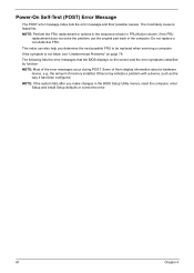
... during POST. Do not replace a non-defective FRU. Others may indicate a problem with a device, such as the way it has been configured. NOTE: Most of memory installed. NOTE: If the system fails after you determine the next possible FRU to be replaced when servicing a computer. Power-On Self-Test (POST) Error...
... during POST. Do not replace a non-defective FRU. Others may indicate a problem with a device, such as the way it has been configured. NOTE: Most of memory installed. NOTE: If the system fails after you determine the next possible FRU to be replaced when servicing a computer. Power-On Self-Test (POST) Error...
TravelMate 4060 Service Guide
Page 77
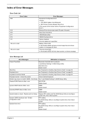
... connector. Incorrect password is dead - Battery critical LOW In this situation BIOS will shut down system, no message will be shown before "Equipment Configuration Error") Memory Error at offset: nnnn DIMM System board System battery is specified. Thermal critical High In this situation BIOS will issue 4 short beeps then shut down...
... connector. Incorrect password is dead - Battery critical LOW In this situation BIOS will shut down system, no message will be shown before "Equipment Configuration Error") Memory Error at offset: nnnn DIMM System board System battery is specified. Thermal critical High In this situation BIOS will issue 4 short beeps then shut down...


