TravelMate 4020 Service Guide
Page 9
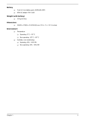
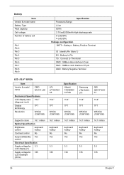
Battery T T 4-cell of Li-ion battery pack, (2200mAh,32W) 65W AC adaptor 19V 3.42A Weight (with battery) T 3.0 kg (6.6 lbs.) Dimensions T 364(W) x 279(D) x 33.9/38.9(H) mm (14.3 x 11 x 1.3/1.5 inches) Environment T Temperature T Operating: 5o C ~ 35o C T Non-operating: -20o C ~ 65o C T Humidity ( non-condensing) T Operating: 20% ~ 80% RH T Non-operating: 20% ~ 80% RH Chapter 1 3
Battery T T 4-cell of Li-ion battery pack, (2200mAh,32W) 65W AC adaptor 19V 3.42A Weight (with battery) T 3.0 kg (6.6 lbs.) Dimensions T 364(W) x 279(D) x 33.9/38.9(H) mm (14.3 x 11 x 1.3/1.5 inches) Environment T Temperature T Operating: 5o C ~ 35o C T Non-operating: -20o C ~ 65o C T Humidity ( non-condensing) T Operating: 20% ~ 80% RH T Non-operating: 20% ~ 80% RH Chapter 1 3
TravelMate 4020 Service Guide
Page 13
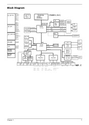
... 2.5VSUS +2.5V +1.8V MVREF_DM SMDDR_VTERM 1.5V_S5 1.5V / 1.05V / 1.8V +1.5V Page : 37 AGP_VCC (+1.5V) 1.2VCCT VTT CPU CORE Page : 34 +1.2V Page : 38 BATTERY CHARGER Page : 39 BATTERY SELECT Page : 40 VCC_CORE VGA_CORE 2.5V_VGA CLOCK GEN ICS ICS954201 Page : 2 Centrino DOTHAN CELEROM-M CRANE2 ( ZL3 ) INTEL Mobile_479 CPU Page : 3 , 4 HOST BUS 533MHz HOST...
... 2.5VSUS +2.5V +1.8V MVREF_DM SMDDR_VTERM 1.5V_S5 1.5V / 1.05V / 1.8V +1.5V Page : 37 AGP_VCC (+1.5V) 1.2VCCT VTT CPU CORE Page : 34 +1.2V Page : 38 BATTERY CHARGER Page : 39 BATTERY SELECT Page : 40 VCC_CORE VGA_CORE 2.5V_VGA CLOCK GEN ICS ICS954201 Page : 2 Centrino DOTHAN CELEROM-M CRANE2 ( ZL3 ) INTEL Mobile_479 CPU Page : 3 , 4 HOST BUS 533MHz HOST...
TravelMate 4020 Service Guide
Page 15
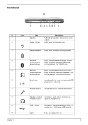
... DescriptDioenscrDipetsiocrniption # Icon Item 1 ## IIccoonn ItIteemmSpeakers Description DeoLsDuecrtftpeipaustntc.idroirnpigthiot snpeakers deliver stereo audio 2 Power indicator Lights when the computer is on. # Icon Item Description 3 Battery indicator Lights when the battery is being charged. 4 Bluetooth Press to Universal Serial Bus (USB) 2.0 devices (e.g., USB mouse, USB camera). Item USB 2.0 port Description Connects to enable/disable...
... DescriptDioenscrDipetsiocrniption # Icon Item 1 ## IIccoonn ItIteemmSpeakers Description DeoLsDuecrtftpeipaustntc.idroirnpigthiot snpeakers deliver stereo audio 2 Power indicator Lights when the computer is on. # Icon Item Description 3 Battery indicator Lights when the battery is being charged. 4 Bluetooth Press to Universal Serial Bus (USB) 2.0 devices (e.g., USB mouse, USB camera). Item USB 2.0 port Description Connects to enable/disable...
TravelMate 4020 Service Guide
Page 19
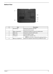
Bottom View # Item Description 1 Hard disk bay Houses the computer's hard disk (secured with two screws). 2 Battery release latch Unlatches the battery to remove the battery pack. 3 Battery bay Houses the computer's battery pack. 4 Battery lock Locks the battery in place. 5 Cooling fan Helps keep the computer cool. Chapter 1 13 NOTE: Do not cover or obstruct the opening of the fan. 6 Memory compartment Houses the computer's main memory and Mini PCI Card.
Bottom View # Item Description 1 Hard disk bay Houses the computer's hard disk (secured with two screws). 2 Battery release latch Unlatches the battery to remove the battery pack. 3 Battery bay Houses the computer's battery pack. 4 Battery lock Locks the battery in place. 5 Cooling fan Helps keep the computer cool. Chapter 1 13 NOTE: Do not cover or obstruct the opening of the fan. 6 Memory compartment Houses the computer's main memory and Mini PCI Card.
TravelMate 4020 Service Guide
Page 27
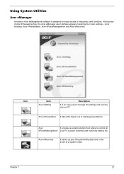
... Acer eManager user interface appears, featuring four main settings -- At the press of a system crash. Acer eSetting, Acer ePresentation, Acer ePowerManagement and Acer eRecovery. Acer eRecovery Acer eRecovery Chapter 1 21 Acer ePresentation AAcAceceerr reePreePsPernertaetsioensnetnItattatkaeisotthineohanssle out of making presentations. Using System Utilities Acer eManager Innovative Acer eManagement software is an easy way to control all AceePorweerMPanoagw emeentrMyouar PnC'as pgoweermscheemnestand maximise battery...
... Acer eManager user interface appears, featuring four main settings -- At the press of a system crash. Acer eSetting, Acer ePresentation, Acer ePowerManagement and Acer eRecovery. Acer eRecovery Acer eRecovery Chapter 1 21 Acer ePresentation AAcAceceerr reePreePsPernertaetsioensnetnItattatkaeisotthineohanssle out of making presentations. Using System Utilities Acer eManager Innovative Acer eManagement software is an easy way to control all AceePorweerMPanoagw emeentrMyouar PnC'as pgoweermscheemnestand maximise battery...
TravelMate 4020 Service Guide
Page 32
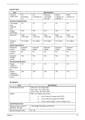
... 6 Pin 7 Pin 8 Pin 9 Specification Panasonic/Sanyo Li-ion 65Wh 3.7V/cell/2000mAh High discharge rate 8-cell(65W) 4-cell(32W) Package configuration BATT+: Battery+, Battery Positive Terminal ID : Identify Pin (Note 1) B/I : Battery-In Pin TS : Connect to Thermister SMD : SMBus data interface I/O pin SMC : SMBus clock interface I/O pin GND... : Battery Negative Terminal LCD :15.4" WXGA Item Vendor & model name CMO N154I1-L09 Mechanical Specifications LCD display area 15.4" (diagonal, inch...
... 6 Pin 7 Pin 8 Pin 9 Specification Panasonic/Sanyo Li-ion 65Wh 3.7V/cell/2000mAh High discharge rate 8-cell(65W) 4-cell(32W) Package configuration BATT+: Battery+, Battery Positive Terminal ID : Identify Pin (Note 1) B/I : Battery-In Pin TS : Connect to Thermister SMD : SMBus data interface I/O pin SMC : SMBus clock interface I/O pin GND... : Battery Negative Terminal LCD :15.4" WXGA Item Vendor & model name CMO N154I1-L09 Mechanical Specifications LCD display area 15.4" (diagonal, inch...
TravelMate 4020 Service Guide
Page 33
... (Hz) Specification Delta 3-pin, 19V 3.95A, 64W Hipro 3-pin, 19V 3.95A, 65W Lite-on 3-pin, 19V 3.95A, 60W 65W Li-ion battery pack (8-cell) T 4-hour battery life (support intel GFX) T 3-hour battery life (support ATI X600) T 1.5-hour quick-charge, 3.5-hour charge-in use 1.8A [email protected]/100Vac and 240 Vac 47 - 63 Chapter...
... (Hz) Specification Delta 3-pin, 19V 3.95A, 64W Hipro 3-pin, 19V 3.95A, 65W Lite-on 3-pin, 19V 3.95A, 60W 65W Li-ion battery pack (8-cell) T 4-hour battery life (support intel GFX) T 3-hour battery life (support ATI X600) T 1.5-hour quick-charge, 3.5-hour charge-in use 1.8A [email protected]/100Vac and 240 Vac 47 - 63 Chapter...
TravelMate 4020 Service Guide
Page 52
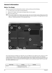
...reference. NOTE: The screws used to see these screws. You may have to upper case but some screws are more than one type. Remove the battery pack. Please pay attention to worry about mix them up. There is for service purpose. Mini PCI cover here also called RAM/Wireless cover. ...Please group same type of screw together as you do the following locations together. IO Bezel Battery The screws that you have to remove the HDD, the heatsink cover to secure bottom case and upper case are inside the system. The image...
...reference. NOTE: The screws used to see these screws. You may have to upper case but some screws are more than one type. Remove the battery pack. Please pay attention to worry about mix them up. There is for service purpose. Mini PCI cover here also called RAM/Wireless cover. ...Please group same type of screw together as you do the following locations together. IO Bezel Battery The screws that you have to remove the HDD, the heatsink cover to secure bottom case and upper case are inside the system. The image...
TravelMate 4020 Service Guide
Page 53
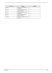
Detach the HDD module 1 then you will see. Remove the battery then you 1 will see. Quantity Chapter 3 47 Remove the heatsink cover 1 then you will see. Screw Type M2.5*6 M2.5*6 M2.5*6 M2.5*3 M2.5*3 Location Remove the IO bezel then 2 you will see. Remove the HDD cover then 1 you will see.
Detach the HDD module 1 then you will see. Remove the battery then you 1 will see. Quantity Chapter 3 47 Remove the heatsink cover 1 then you will see. Screw Type M2.5*6 M2.5*6 M2.5*6 M2.5*3 M2.5*3 Location Remove the IO bezel then 2 you will see. Remove the HDD cover then 1 you will see.
TravelMate 4020 Service Guide
Page 54
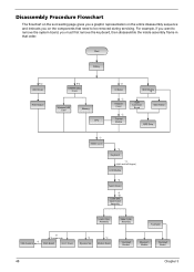
For example, if you want to be removed during servicing. Start Battery K*2 HDD Cover HDD Module E*2 RAM/Wireless Cover Wireless LAN Card Memory CPU *2 IO Bezel *2 Heatsink Cover *2 Thermal Module ODD Module *6 ODD Connector Board ODD Holder ...
For example, if you want to be removed during servicing. Start Battery K*2 HDD Cover HDD Module E*2 RAM/Wireless Cover Wireless LAN Card Memory CPU *2 IO Bezel *2 Heatsink Cover *2 Thermal Module ODD Module *6 ODD Connector Board ODD Holder ...
TravelMate 4020 Service Guide
Page 56
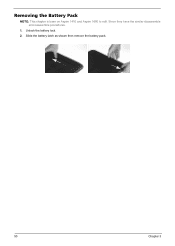
Unlock the battery lock. 2. Removing the Battery Pack NOTE: This chapter is base on Aspire 1410 and Aspire 1680 to edit. Since they have the similar disassemble and reassemble procedures. 1. Slide the battery latch as shown then remove the battery pack. 50 Chapter 3
Unlock the battery lock. 2. Removing the Battery Pack NOTE: This chapter is base on Aspire 1410 and Aspire 1680 to edit. Since they have the similar disassemble and reassemble procedures. 1. Slide the battery latch as shown then remove the battery pack. 50 Chapter 3
TravelMate 4020 Service Guide
Page 71
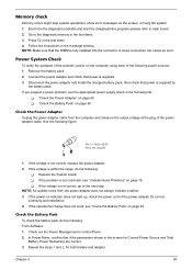
...is within the range, do the following power sources: 1. See the following : T Replace the System board. If the voltage is supplied by the battery pack. If the operational charge does not work, see "Undetermined Problems" on page 65. Repeat the steps 1 and 2, for correct continuity and installation....screen, or hang the system. 1. Check out the Power Management in the test items. 3. Disconnect the power adapter and install the charged battery pack; NOTE: An audible noise from the diagnostics diskette and start the doagmpstotics program (please refer to +20.5V Pin 2: 0V, Ground ...
...is within the range, do the following power sources: 1. See the following : T Replace the System board. If the voltage is supplied by the battery pack. If the operational charge does not work, see "Undetermined Problems" on page 65. Repeat the steps 1 and 2, for correct continuity and installation....screen, or hang the system. 1. Check out the Power Management in the test items. 3. Disconnect the power adapter and install the charged battery pack; NOTE: An audible noise from the diagnostics diskette and start the doagmpstotics program (please refer to +20.5V Pin 2: 0V, Ground ...
TravelMate 4020 Service Guide
Page 72
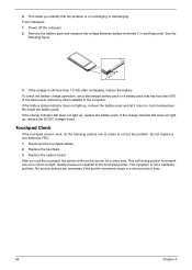
...the problem is still less than 50% of time. 66 Chapter 4 This helps you use a discharged battery pack or a battery pack that has less than 7.5 Vdc after recharging, replace the battery. Replace the system board. No service actions are necessary if the pointer movement stops in a short period... the computer. 2. If the voltage is on the screen for a short time. If the charge indicator still does not light up, replace the battery pack. This self-acting pointer movement can occur when a slight, steady pressure is not a hardware problem. See the following actions one at a time...
...the problem is still less than 50% of time. 66 Chapter 4 This helps you use a discharged battery pack or a battery pack that has less than 7.5 Vdc after recharging, replace the battery. Replace the system board. No service actions are necessary if the pointer movement stops in a short period... the computer. 2. If the voltage is on the screen for a short time. If the charge indicator still does not light up, replace the battery pack. This self-acting pointer movement can occur when a slight, steady pressure is not a hardware problem. See the following actions one at a time...
TravelMate 4020 Service Guide
Page 74
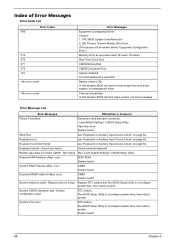
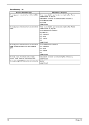
... Error Messages Equipment Configuration Error Causes: 1. Run Setup Run "Load Default Settings" in BIOS Setup Utility. System timer error RTC battery Run BIOS Setup Utility to reconfigure system time, then reboot system. Hard disk drive System board Stuck Key see "Keyboard or Auxiliary... Input Device Check" on page 64. Default configuration used RTC battery Run BIOS Setup Utility to reconfigure system time, then reboot system. Thermal critical High In this situation BIOS will issue 4 short ...
... Error Messages Equipment Configuration Error Causes: 1. Run Setup Run "Load Default Settings" in BIOS Setup Utility. System timer error RTC battery Run BIOS Setup Utility to reconfigure system time, then reboot system. Hard disk drive System board Stuck Key see "Keyboard or Auxiliary... Input Device Check" on page 64. Default configuration used RTC battery Run BIOS Setup Utility to reconfigure system time, then reboot system. Thermal critical High In this situation BIOS will issue 4 short ...
TravelMate 4020 Service Guide
Page 75
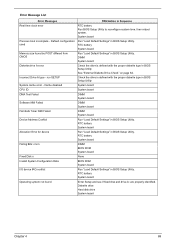
...DIMM System board Fail-Safe Timer NMI Failed DIMM System board Device Address Conflict Run "Load Default Settings" in BIOS Setup Utility. RTC battery System board Failing Bits: nnnn DIMM BIOS ROM System board Fixed Disk n None Invalid System Configuration Data BIOS ROM System board I/O device... IRQ conflict Run "Load Default Settings" in Sequence Real time clock error RTC battery Run BIOS Setup Utility to reconfigure system time, then reboot system. Error Message List Error Messages FRU/Action in BIOS Setup Utility. RTC...
...DIMM System board Fail-Safe Timer NMI Failed DIMM System board Device Address Conflict Run "Load Default Settings" in BIOS Setup Utility. RTC battery System board Failing Bits: nnnn DIMM BIOS ROM System board Fixed Disk n None Invalid System Configuration Data BIOS ROM System board I/O device... IRQ conflict Run "Load Default Settings" in Sequence Real time clock error RTC battery Run BIOS Setup Utility to reconfigure system time, then reboot system. Error Message List Error Messages FRU/Action in BIOS Setup Utility. RTC...
TravelMate 4020 Service Guide
Page 76
Power source (battery pack and power adapter). Ensure every connector is connected tightly and correctly System board No beep during POST. Reconnect the DIMM. System board. Reconnect the ...-on indicator turns off and LCD is connected tightly and correctly. See "Power System Check" on page 65. Ensure every connector is blank. Power source (battery pack and power adapter).
Power source (battery pack and power adapter). Ensure every connector is connected tightly and correctly System board No beep during POST. Reconnect the DIMM. System board. Reconnect the ...-on indicator turns off and LCD is connected tightly and correctly. See "Power System Check" on page 65. Ensure every connector is blank. Power source (battery pack and power adapter).
TravelMate 4020 Service Guide
Page 81
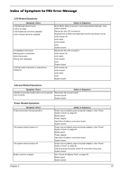
... power switch for more than 4 seconds. System board See "Check the Battery Pack" on page 65. Battery pack Power adapter Hard drive & battery connection board System board Power source (battery pack and power adapter). Reconnect the LCD connectors. LCD inverter ID LCD ...Indicator-Related Symptoms Symptom / Error Action in Sequence Indicator incorrectly remains off . Battery pack Power adapter Hard drive & battery connection board System board Power source (battery pack and power adapter). Battery pack System board Chapter 4 75 Action in Sequence Enter BIOS Utility to ...
... power switch for more than 4 seconds. System board See "Check the Battery Pack" on page 65. Battery pack Power adapter Hard drive & battery connection board System board Power source (battery pack and power adapter). Reconnect the LCD connectors. LCD inverter ID LCD ...Indicator-Related Symptoms Symptom / Error Action in Sequence Indicator incorrectly remains off . Battery pack Power adapter Hard drive & battery connection board System board Power source (battery pack and power adapter). Battery pack System board Chapter 4 75 Action in Sequence Enter BIOS Utility to ...
TravelMate 4020 Service Guide
Page 82
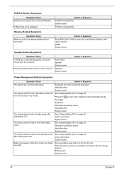
... drive System board The system doesn't enter standby mode after opening the LCD. Remove battery pack and let it cool for 2 hours Refresh battery (continue use battery until power off, then charge battery) Battery pack System board 76 Chapter 4 Action in Sequence The system will not enter hibernation ...emit no sound comes from hibernation mode. Press Fn+oand see if the computer enters hibernation mode. LCD cover switch System board Battery fuel gauge in Sequence Enter BIOS Setup Utility to execute "Load Default Settings, then reboot system. Action in Windows doesn't go ...
... drive System board The system doesn't enter standby mode after opening the LCD. Remove battery pack and let it cool for 2 hours Refresh battery (continue use battery until power off, then charge battery) Battery pack System board 76 Chapter 4 Action in Sequence The system will not enter hibernation ...emit no sound comes from hibernation mode. Press Fn+oand see if the computer enters hibernation mode. LCD cover switch System board Battery fuel gauge in Sequence Enter BIOS Setup Utility to execute "Load Default Settings, then reboot system. Action in Windows doesn't go ...
TravelMate 4020 Service Guide
Page 85
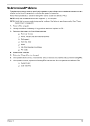
... you find the failing FRU. 7. If any problems are supported by the computer. If the problem remains, replace the following devices: T Non-Acer devices T Printer, mouse, and other external devices T Battery pack T Hard disk drive T DIMM T CD-ROM/Diskette drive Module T PC Cards 4. Undetermined Problems The diagnostic problems does not identify which...
... you find the failing FRU. 7. If any problems are supported by the computer. If the problem remains, replace the following devices: T Non-Acer devices T Printer, mouse, and other external devices T Battery pack T Hard disk drive T DIMM T CD-ROM/Diskette drive Module T PC Cards 4. Undetermined Problems The diagnostic problems does not identify which...
TravelMate 4020 Service Guide
Page 88
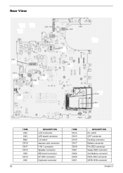
Rear View ITEM CN2 CN3 SW2 CN10 CN11 CN13 CN9 CN12 CN5 DESCRIPTION LCD Connector LED board connector Lid switch express card connector 4 IN 1 connector Speaker connector MD board connector INT MIC connector Keyboard connector 82 ITEM CN14 CN15 CN16 CN17 CN18 CN21 CN24 CN30 CN31 DESCRIPTION DC JACK CRT connector Docking connector Battery connector Fix ODD connector Swap ODD connector 2nd Battery connector PATA HDD connector SATA HDD connector Chapter 5
Rear View ITEM CN2 CN3 SW2 CN10 CN11 CN13 CN9 CN12 CN5 DESCRIPTION LCD Connector LED board connector Lid switch express card connector 4 IN 1 connector Speaker connector MD board connector INT MIC connector Keyboard connector 82 ITEM CN14 CN15 CN16 CN17 CN18 CN21 CN24 CN30 CN31 DESCRIPTION DC JACK CRT connector Docking connector Battery connector Fix ODD connector Swap ODD connector 2nd Battery connector PATA HDD connector SATA HDD connector Chapter 5


