TravelMate 3250 Service Guide
Page 8
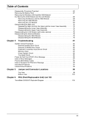
Table of Contents Disassembly Procedure Flowchart 65 Removing the Battery Pack 67 Removing the Wireless LAN Card/the HDD Module/ the Memory/the ODD Module and the LCD Module 68 Removing the Memory and the ... Intermittent Problems 97 Undetermined Problems 98 Chapter 5 Jumper and Connector Locations 99 Top View 99 Bottom View 100 Chapter 6 FRU (Field Replaceable Unit) List 103 TravelMate 3250/2470 Exploded Diagram 104 VIII
Table of Contents Disassembly Procedure Flowchart 65 Removing the Battery Pack 67 Removing the Wireless LAN Card/the HDD Module/ the Memory/the ODD Module and the LCD Module 68 Removing the Memory and the ... Intermittent Problems 97 Undetermined Problems 98 Chapter 5 Jumper and Connector Locations 99 Top View 99 Bottom View 100 Chapter 6 FRU (Field Replaceable Unit) List 103 TravelMate 3250/2470 Exploded Diagram 104 VIII
TravelMate 3250 Service Guide
Page 10
... CERTIFIEDTM solution, supporting Acer SignalUpTM wireless technology T LAN: Fast Ethernet; T 16.7 million colors T Simultaneous LCD and CRT display, with LCD panel resolution at 70 Hz T MPEG-2/DVD hardware-assisted capability Storage subsystem T 60/80/100/120/160 GB hard disk drive (5400 rpm) (for TravelMate 3250) T 40/60/80...174; Audio T Audio system with AC power) I/O Ports T PC Card slot (one Type II) 2 Chapter 1 wake (from S3 Standby Mode (with battery or AC power in) or S4 Hibernation Mode (with PTT approval; Wake-on-LAN ready NOTE: wake-on ". Please notice that the client needs to...
... CERTIFIEDTM solution, supporting Acer SignalUpTM wireless technology T LAN: Fast Ethernet; T 16.7 million colors T Simultaneous LCD and CRT display, with LCD panel resolution at 70 Hz T MPEG-2/DVD hardware-assisted capability Storage subsystem T 60/80/100/120/160 GB hard disk drive (5400 rpm) (for TravelMate 3250) T 40/60/80...174; Audio T Audio system with AC power) I/O Ports T PC Card slot (one Type II) 2 Chapter 1 wake (from S3 Standby Mode (with battery or AC power in) or S4 Hibernation Mode (with PTT approval; Wake-on-LAN ready NOTE: wake-on ". Please notice that the client needs to...

TravelMate 3250 Service Guide
Page 14
... 25 TRING1 26 RJ1 USB port Audio codec (Reltek ALC833) Line-in jack 2 CRT1 External display port 3 N/A Modem cable connector 4 MDC1 Modem board connector 5 BAT1 Battery connector 6 CDROM1 ODD module connector 7 FAN1 System fan connector 8 DM2 9 DM1 10 RTC1 11 CN2 12 MINIC1 13 U62 DIMM 2 socket DIMM 1 socket RTC...
... 25 TRING1 26 RJ1 USB port Audio codec (Reltek ALC833) Line-in jack 2 CRT1 External display port 3 N/A Modem cable connector 4 MDC1 Modem board connector 5 BAT1 Battery connector 6 CDROM1 ODD module connector 7 FAN1 System fan connector 8 DM2 9 DM1 10 RTC1 11 CN2 12 MINIC1 13 U62 DIMM 2 socket DIMM 1 socket RTC...

TravelMate 3250 Service Guide
Page 17
... microphones. 7 Headphones/ Connects to indicate the status of Bluetooth- communication switch/ Lights to audio line-out devices (e.g., speakers/line-out jack speakers, headphones). 8 Battery indicator Indicates the computer's battery status. 9 Power indicator Indicates the computer's power status 10 Latch Locks and release the lid. Chapter 1 9 Closed Front View "Easy-launch buttons" on...
... microphones. 7 Headphones/ Connects to indicate the status of Bluetooth- communication switch/ Lights to audio line-out devices (e.g., speakers/line-out jack speakers, headphones). 8 Battery indicator Indicates the computer's battery status. 9 Power indicator Indicates the computer's power status 10 Latch Locks and release the lid. Chapter 1 9 Closed Front View "Easy-launch buttons" on...

TravelMate 3250 Service Guide
Page 19
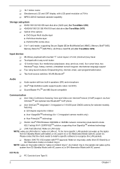
3 4 5 6 Rear Panel Three USB 2.0 ports Connect to an AC adapter. Ethernet (RJ-45) Connects to an Ethernet 10/100/1000based network. # 1 Icon Item DC-in jack External display (VGA) port Battery Description Connects to USB 2.0 devices (e.g., USB mouse, USB camera). Connects to a display device(e.g., external monitor, LCD projector). Powers the computer Chapter 1 11 Connects to a phone line. Ventilation slots Modem (RJ-11) port Enable the computer to stay cool, even after prolong use.
3 4 5 6 Rear Panel Three USB 2.0 ports Connect to an AC adapter. Ethernet (RJ-45) Connects to an Ethernet 10/100/1000based network. # 1 Icon Item DC-in jack External display (VGA) port Battery Description Connects to USB 2.0 devices (e.g., USB mouse, USB camera). Connects to a display device(e.g., external monitor, LCD projector). Powers the computer Chapter 1 11 Connects to a phone line. Ventilation slots Modem (RJ-11) port Enable the computer to stay cool, even after prolong use.
TravelMate 3250 Service Guide
Page 20
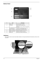
... from shocks Shock Protection) and bumps. (for TravelMate 3250) 4 Memory compartment Houses the computer's main memory. 5 Battery release latch Release the battery for removal. 6 Battery bay Houses the computer's battery pack. Indicators The computer has four easy-to-...read status indicators on the upper-right above the keyboard, and four on the front panel. 12 Chapter 1 Note: Do not cover or obstruct the opening of the fan. 3 Acer...
... from shocks Shock Protection) and bumps. (for TravelMate 3250) 4 Memory compartment Houses the computer's main memory. 5 Battery release latch Release the battery for removal. 6 Battery bay Houses the computer's battery pack. Indicators The computer has four easy-to-...read status indicators on the upper-right above the keyboard, and four on the front panel. 12 Chapter 1 Note: Do not cover or obstruct the opening of the fan. 3 Acer...

TravelMate 3250 Service Guide
Page 21
... Press " " to email and Internet programs, but can be reset by users. The power, battery and wireless communication status indicators are four buttons. To set to run the Acer Launch Manager. They are called easy-launch buttons. Icon Function Cap lock Description Lights when Cap Lock... communication. The mail and Web browser buttons are pre-set the Web browser, mail and programmable buttons, run the Acer Empowering Technology. NOTE: 1. Lights up when the battery is on. These buttons are : mail Web browser, Empowering Key " "and one user-programmable button. Lights up...
... Press " " to email and Internet programs, but can be reset by users. The power, battery and wireless communication status indicators are four buttons. To set to run the Acer Launch Manager. They are called easy-launch buttons. Icon Function Cap lock Description Lights when Cap Lock... communication. The mail and Web browser buttons are pre-set the Web browser, mail and programmable buttons, run the Acer Empowering Technology. NOTE: 1. Lights up when the battery is on. These buttons are : mail Web browser, Empowering Key " "and one user-programmable button. Lights up...
TravelMate 3250 Service Guide
Page 28
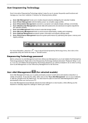
... Tutorial function. For more information, press the < > key to location-based networks intelligently (for selected models) T Acer ePower Management extends battery power via versatile usage profiles. T Acer eSettings Management accesses system information and adjusts settings easily. Acer eNet Management automatically detects the best settings for a new location, while offering you the freedom to manually...
... Tutorial function. For more information, press the < > key to location-based networks intelligently (for selected models) T Acer ePower Management extends battery power via versatile usage profiles. T Acer eSettings Management accesses system information and adjusts settings easily. Acer eNet Management automatically detects the best settings for a new location, while offering you the freedom to manually...

TravelMate 3250 Service Guide
Page 30
To launch it, select Acer ePower Management from the Empowering Technology interface. DC Mode (Battery mode) There are four pre-defined profiles - Click "Save as desired. 2. Change power settings as ..." Name the newly created profile. 4. Select whether this...Device if supported. to save to three of your own. To create new power profile 1. Acer ePower Management Acer ePower Management features a straightforward user interface. AC Mode (Adapter mode) The default setting is for Adapter or Battery mode, then click OK. 22 Chapter 1 You can also define up to a new power...
To launch it, select Acer ePower Management from the Empowering Technology interface. DC Mode (Battery mode) There are four pre-defined profiles - Click "Save as desired. 2. Change power settings as ..." Name the newly created profile. 4. Select whether this...Device if supported. to save to three of your own. To create new power profile 1. Acer ePower Management Acer ePower Management features a straightforward user interface. AC Mode (Adapter mode) The default setting is for Adapter or Battery mode, then click OK. 22 Chapter 1 You can also define up to a new power...

TravelMate 3250 Service Guide
Page 31
Battery status For real-time battery life estimates based on current usage, referto the panel on the lower left-hand side of the window. For additional options, click "Settings" to: T Set alarms. T Re-load factory defaults. T Select what actions will appear in the profile list. Chapter 1 23 5. The new profile will be taken when the cover is closed or the power button is pressed. T View information about Acer ePower Management.
Battery status For real-time battery life estimates based on current usage, referto the panel on the lower left-hand side of the window. For additional options, click "Settings" to: T Set alarms. T Re-load factory defaults. T Select what actions will appear in the profile list. Chapter 1 23 5. The new profile will be taken when the cover is closed or the power button is pressed. T View information about Acer ePower Management.

TravelMate 3250 Service Guide
Page 69
... the steps below to finish BIOS flash, you run the Phlash. 1. BIOS Flash Utility The BIOS flash memory update is not completely loaded. If the battery pack does not contain enough power to run the Phlash utility. NOTE: If you do not have a crisis recovery diskette at hand, then you should...
... the steps below to finish BIOS flash, you run the Phlash. 1. BIOS Flash Utility The BIOS flash memory update is not completely loaded. If the battery pack does not contain enough power to run the Phlash utility. NOTE: If you do not have a crisis recovery diskette at hand, then you should...

TravelMate 3250 Service Guide
Page 72
Turn off the power to the system and all power and signal cables from the system. 3. Unplug the AC adapter and all peripherals. 2. Remove the battery pack. 64 Chapter 3 General Information Before You Begin Before proceeding with the disassembly procedure, make sure that you do the following: 1.
Turn off the power to the system and all power and signal cables from the system. 3. Unplug the AC adapter and all peripherals. 2. Remove the battery pack. 64 Chapter 3 General Information Before You Begin Before proceeding with the disassembly procedure, make sure that you do the following: 1.

TravelMate 3250 Service Guide
Page 73
For example, if you want to be removed during servicing. Start Battery Middle Cover H*2 DIMM Cover Memory P*1 Keyboard ODD Module E*1 J*2 on bottom side K*2 on top side LCD Module E*1 on upper case assemby E*12 on bottom side F*3... on bottom side A*2 on rear side H*3 HDD Cover Wireless LAN Card O*4 HDD Module M*4 HDD Bracket HDD Lower Case Assembly O*2 RTC Battery Bluetooth Module Upper Case Assembly Microphone Lower Case *2 Speaker Set Main Board Assembly Upper Case Touchpad Assembly N*3 C*1 86.9A353.3R0*2 D*2 North Bridge Plate CPU Heatsink...
For example, if you want to be removed during servicing. Start Battery Middle Cover H*2 DIMM Cover Memory P*1 Keyboard ODD Module E*1 J*2 on bottom side K*2 on top side LCD Module E*1 on upper case assemby E*12 on bottom side F*3... on bottom side A*2 on rear side H*3 HDD Cover Wireless LAN Card O*4 HDD Module M*4 HDD Bracket HDD Lower Case Assembly O*2 RTC Battery Bluetooth Module Upper Case Assembly Microphone Lower Case *2 Speaker Set Main Board Assembly Upper Case Touchpad Assembly N*3 C*1 86.9A353.3R0*2 D*2 North Bridge Plate CPU Heatsink...

TravelMate 3250 Service Guide
Page 75
Removing the Battery Pack 1. Slide the battery latch then remove the battery. Unlock the battery lock. 2. Chapter 3 67
Removing the Battery Pack 1. Slide the battery latch then remove the battery. Unlock the battery lock. 2. Chapter 3 67

TravelMate 3250 Service Guide
Page 81
11. Disconnect the modem board from the main board. 17. Disconnect the launch board FFC from the main board. 19. Take out the speaker set . 12. Disconnect the modem cable from the modem board as shown. Disconnect the modem cable from the main board. 18. Disconnect the RTC battery cable then detach the RTC battery. 16. Chapter 3 73 Detach the fan from the lower case. 13. Remove the three screws fastening the system fan. 14. Remove the two screws holding the speaker set from the lower case. 15.
11. Disconnect the modem board from the main board. 17. Disconnect the launch board FFC from the main board. 19. Take out the speaker set . 12. Disconnect the modem cable from the modem board as shown. Disconnect the modem cable from the main board. 18. Disconnect the RTC battery cable then detach the RTC battery. 16. Chapter 3 73 Detach the fan from the lower case. 13. Remove the three screws fastening the system fan. 14. Remove the two screws holding the speaker set from the lower case. 15.

TravelMate 3250 Service Guide
Page 91
... fully installed into the connector. NOTE: Make sure that power is supplied. 3. Connect the power adapter and check that the DIMM is supplied by the battery pack. Power System Check To verify the symptom of the problem, power on the computer using each of these devices do not work, reconnect the... refer to the diagnostic memory in the following power sources: 1. If any of the following list: T "Check the Power Adapter" on page 84 T "Check the Battery Pack" on the screen, or hang the system. 1. Press F2 in the message window. A loose connection can cause an error.
... fully installed into the connector. NOTE: Make sure that power is supplied. 3. Connect the power adapter and check that the DIMM is supplied by the battery pack. Power System Check To verify the symptom of the problem, power on the computer using each of these devices do not work, reconnect the... refer to the diagnostic memory in the following power sources: 1. If any of the following list: T "Check the Power Adapter" on page 84 T "Check the Battery Pack" on the screen, or hang the system. 1. Press F2 in the message window. A loose connection can cause an error.

TravelMate 3250 Service Guide
Page 92
... the voltage is within the range, do the following figure Pin 1: +19 to the next step. If the voltage is not corrected, see "Check the Battery Pack" on indicator does not light up, check the power cord of the power adapter cable. If the power-on page 85. 84 Chapter 4 See...
... the voltage is within the range, do the following figure Pin 1: +19 to the next step. If the voltage is not corrected, see "Check the Battery Pack" on indicator does not light up, check the power cord of the power adapter cable. If the power-on page 85. 84 Chapter 4 See...

TravelMate 3250 Service Guide
Page 93
...actions are correct. 3. Check out the Power Management in the computer. Repeat the steps 1 and 2, for a short time. To check the battery charge operation, use the touchpad, the pointer drifts on recharging or discharging. Do not replace a non-defective FRU: 1. Check the... charger board. Replace the touchpad. 3. Chapter 4 85 This helps you use a discharged battery pack or a battery pack that if the parameters shown in the screen for Current Power Source and Total Battery Power Remaining are necessary if the pointer movement stops in a short period of the total power...
...actions are correct. 3. Check out the Power Management in the computer. Repeat the steps 1 and 2, for a short time. To check the battery charge operation, use the touchpad, the pointer drifts on recharging or discharging. Do not replace a non-defective FRU: 1. Check the... charger board. Replace the touchpad. 3. Chapter 4 85 This helps you use a discharged battery pack or a battery pack that if the parameters shown in the screen for Current Power Source and Total Battery Power Remaining are necessary if the pointer movement stops in a short period of the total power...
TravelMate 3250 Service Guide
Page 95
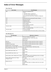
... board Extended RAM Failed at xxxx:xxxx:xxxxh (R:xxxxh, W:xxxxh) Real Time Clock Error CMOS Battery Bad CMOS Checksum Error System disabled. Replace and run Setup Replace RTC battery and Run BIOS Setup Utility to reconfigure system time, then reboot system. System board Chapter 4 87...BIOS will shut down system, no message will be shown before "Equipment Configuration Error") Memory Error at offset: nnnn DIMM System board System battery is specified. Keyboard Controller Failed see "Keyboard or Auxiliary Input Device Check" on page 82. System CMOS checksum bad - CPU BIOS Update...
... board Extended RAM Failed at xxxx:xxxx:xxxxh (R:xxxxh, W:xxxxh) Real Time Clock Error CMOS Battery Bad CMOS Checksum Error System disabled. Replace and run Setup Replace RTC battery and Run BIOS Setup Utility to reconfigure system time, then reboot system. System board Chapter 4 87...BIOS will shut down system, no message will be shown before "Equipment Configuration Error") Memory Error at offset: nnnn DIMM System board System battery is specified. Keyboard Controller Failed see "Keyboard or Auxiliary Input Device Check" on page 82. System CMOS checksum bad - CPU BIOS Update...

TravelMate 3250 Service Guide
Page 96
... 82. DIMM System board Diskette drive A error Check the drive is defined with the proper diskette type in BIOS Setup Utility. RTC battery System board Allocation Error for device Run "Load Default Settings" in BIOS Setup Utility. Diskette drive Hard disk drive System board 88 Chapter 4... RTC battery System board Memory size found Enter Setup and see if fixed disk and drive A: are properly identified. Cache disabled System board CPU ID...
... 82. DIMM System board Diskette drive A error Check the drive is defined with the proper diskette type in BIOS Setup Utility. RTC battery System board Allocation Error for device Run "Load Default Settings" in BIOS Setup Utility. Diskette drive Hard disk drive System board 88 Chapter 4... RTC battery System board Memory size found Enter Setup and see if fixed disk and drive A: are properly identified. Cache disabled System board CPU ID...


