TravelMate 220 Service Guide
Page 2
... specifications for Combo driver. to Mitsubishi and its specifications in CDROM interface. Add (DVD + CD-RW) for battery. Remove ELPIDA 128 and 256MB for memory specifications Remove TEAC for the updates made on Travelmate 220/260 service guide. Revision History Please refer to DVD/CD-R/CD-RW and modify... battery specs. . II Remove US 2 pin for Power Code: Change DVD-RW to the table below for DVD-ROM...
... specifications for Combo driver. to Mitsubishi and its specifications in CDROM interface. Add (DVD + CD-RW) for battery. Remove ELPIDA 128 and 256MB for memory specifications Remove TEAC for the updates made on Travelmate 220/260 service guide. Revision History Please refer to DVD/CD-R/CD-RW and modify... battery specs. . II Remove US 2 pin for Power Code: Change DVD-RW to the table below for DVD-ROM...

TravelMate 220 Service Guide
Page 7
... PQA Diagnostics Program 41 Chapter 3 Machine Disassembly and Replacement 44 General Information 45 Before You Begin 45 Disassembly Procedure Flowchart 46 Removing the Battery Pack 49 Removing the Battery Cover 49 Removing the CD-ROM Drive Module 50 Disassembling the CD-ROM Drive Module 50 Removing the Hard Disk Drive Module 52...
... PQA Diagnostics Program 41 Chapter 3 Machine Disassembly and Replacement 44 General Information 45 Before You Begin 45 Disassembly Procedure Flowchart 46 Removing the Battery Pack 49 Removing the Battery Cover 49 Removing the CD-ROM Drive Module 50 Disassembling the CD-ROM Drive Module 50 Removing the Hard Disk Drive Module 52...
TravelMate 220 Service Guide
Page 8
... the LCD Coaxial Cable 65 Removing the Microphone Cable 66 Disassembling the Main Unit 67 Removing the CPU Heat Sink Plate 67 Removing the RTC Battery 67 Removing the Touch Pad Frame 67 Removing the Touch Pad Cable 68 Removing the Upper Case 69 Removing the RTC... Battery Holder 70 Removing the Floppy Disk Drive Module 70 Disassembling the Floppy Disk Drive Module 71 Removing the Charger Plate 72 Removing the CPU Heat ...
... the LCD Coaxial Cable 65 Removing the Microphone Cable 66 Disassembling the Main Unit 67 Removing the CPU Heat Sink Plate 67 Removing the RTC Battery 67 Removing the Touch Pad Frame 67 Removing the Touch Pad Cable 68 Removing the Upper Case 69 Removing the RTC... Battery Holder 70 Removing the Floppy Disk Drive Module 70 Disassembling the Floppy Disk Drive Module 71 Removing the Charger Plate 72 Removing the CPU Heat ...
TravelMate 220 Service Guide
Page 11
... windows to conserve power when you to boost video performance. The computer employs a microswitch that automatically dims the LCD when the computer is powered by a battery pack to an external display device, such as LCD projection panels for giving presentations. WARNING: To avoid damaging the display, do not place any object... that automatically decides the best settings for more information on top of Windows ME's multi-display capability, allowing you to extend your desktop to conserve battery power. If you prefer, you close the display cover.
... windows to conserve power when you to boost video performance. The computer employs a microswitch that automatically dims the LCD when the computer is powered by a battery pack to an external display device, such as LCD projection panels for giving presentations. WARNING: To avoid damaging the display, do not place any object... that automatically decides the best settings for more information on top of Windows ME's multi-display capability, allowing you to extend your desktop to conserve battery power. If you prefer, you close the display cover.
TravelMate 220 Service Guide
Page 13
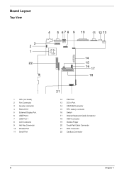
Board Layout Top View 3 2 1 22 4 5 6 7 8 9 10 11 12 13 14 15 16 17 18 1 CPU (on board) 2 Fan Connector 3 Inverter connector 4 RJ45+RJ11 5 External Display Port 6 USB Port 0 7 USB Port 1 8 LCD Connecto 9 Hot Key Connector 10 Parallel Port 11 Serial Port 21 12 PS/2 Port 13 DC-in Port 14 CD-ROM Connector 15 RTC battery connecto 16 Switch 17 Internal Keyboard Cable Connector 18 HDD Connector 19 Golden Finger 20 TouchPad Cable Connector 21 FDD Connector 22 Cardbus Connector 4 Chapter 1
Board Layout Top View 3 2 1 22 4 5 6 7 8 9 10 11 12 13 14 15 16 17 18 1 CPU (on board) 2 Fan Connector 3 Inverter connector 4 RJ45+RJ11 5 External Display Port 6 USB Port 0 7 USB Port 1 8 LCD Connecto 9 Hot Key Connector 10 Parallel Port 11 Serial Port 21 12 PS/2 Port 13 DC-in Port 14 CD-ROM Connector 15 RTC battery connecto 16 Switch 17 Internal Keyboard Cable Connector 18 HDD Connector 19 Golden Finger 20 TouchPad Cable Connector 21 FDD Connector 22 Cardbus Connector 4 Chapter 1

TravelMate 220 Service Guide
Page 14
Bottom View 1 9 8 1 Modem Connector 2 North Bridge(82830MG) 3 Power Switch 4 Audio Board Connector 5 DIMM 2 Socket 2 3 4 76 5 6 DIMM 1 Socket 7 Modem Card Cable Connector 8 Battery Connecto 9 South Bridge (ICH3-M) Chapter 1 5
Bottom View 1 9 8 1 Modem Connector 2 North Bridge(82830MG) 3 Power Switch 4 Audio Board Connector 5 DIMM 2 Socket 2 3 4 76 5 6 DIMM 1 Socket 7 Modem Card Cable Connector 8 Battery Connecto 9 South Bridge (ICH3-M) Chapter 1 5
TravelMate 220 Service Guide
Page 17
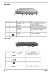
... Parallel port USB port (two) Connects to any Universal Serial Bus devices(e.g., USB mouse, USB camera). Right Panel # 1 2 3 4 5 6 7 Icon Item/ Port Video capture kit slot Battery bay AcerMedia drive LED indicator Eject button Emergency eject slot Power Jack Rear Panel l Connects to... Ejects the compact disc from the drive. Chapter 1 Houses...
... Parallel port USB port (two) Connects to any Universal Serial Bus devices(e.g., USB mouse, USB camera). Right Panel # 1 2 3 4 5 6 7 Icon Item/ Port Video capture kit slot Battery bay AcerMedia drive LED indicator Eject button Emergency eject slot Power Jack Rear Panel l Connects to... Ejects the compact disc from the drive. Chapter 1 Houses...

TravelMate 220 Service Guide
Page 18
...hard disk against shocks. Houses an AcerMedia drive module. Insert a business card or similar-sized identification card to remove the battery pack. # Icon Port Connects to... 5 External display port Connects to a display device (e.g., external monitor, LCD projector) ...1 2 3 4 5 6 7 8 Item Memory compartment Hard disk anti-shock protection Personal identification slot AcerMedia bay release latch AcerMedia bay Battery bay Battery release latch Hard disk bay Description Houses the computer's main memory. Houses the computer's hard disk (secured by a screw). Chapter 1 9 ...
...hard disk against shocks. Houses an AcerMedia drive module. Insert a business card or similar-sized identification card to remove the battery pack. # Icon Port Connects to... 5 External display port Connects to a display device (e.g., external monitor, LCD projector) ...1 2 3 4 5 6 7 8 Item Memory compartment Hard disk anti-shock protection Personal identification slot AcerMedia bay release latch AcerMedia bay Battery bay Battery release latch Hard disk bay Description Houses the computer's main memory. Houses the computer's hard disk (secured by a screw). Chapter 1 9 ...

TravelMate 220 Service Guide
Page 19
... when it enters into or resumes from hibernation mode. 3 Media Activity Lights when the floppy drive, hard disk or AcerMedia drive is active. 4 Battery Charge Lights when the battery is being charged. 5 Caps Lock Lights when Caps Lock is activated. 6 Num Lock Lights when Numeric Lock is activated. (Fn-F11) 10 Chapter...
... when it enters into or resumes from hibernation mode. 3 Media Activity Lights when the floppy drive, hard disk or AcerMedia drive is active. 4 Battery Charge Lights when the battery is being charged. 5 Caps Lock Lights when Caps Lock is activated. 6 Num Lock Lights when Numeric Lock is activated. (Fn-F11) 10 Chapter...
TravelMate 220 Service Guide
Page 32
key Yes Yes Battery Item Vendor & model name Battery Type Pack capacity Cell voltage Number of keypads Windows 95 keys Internal & external keyboard work simultaneously Specification Mitsubishi M38859FFHP API 84-/85/87- Serial Port ... III/II One type III or one type II Left side Yes Yes (IRQ9) Keyboard Item Keyboard controller Keyboard vendor & model name Total number of battery cell Package configuration Package voltage SIMPLO Li-ION / Ni-MH 4000mAH / 4500mAH 3.7V / 1.2V 8 4529 / 8S 14.8V / 9.6V Specification DC-DC/Charger Converter Item...
key Yes Yes Battery Item Vendor & model name Battery Type Pack capacity Cell voltage Number of keypads Windows 95 keys Internal & external keyboard work simultaneously Specification Mitsubishi M38859FFHP API 84-/85/87- Serial Port ... III/II One type III or one type II Left side Yes Yes (IRQ9) Keyboard Item Keyboard controller Keyboard vendor & model name Total number of battery cell Package configuration Package voltage SIMPLO Li-ION / Ni-MH 4000mAH / 4500mAH 3.7V / 1.2V 8 4529 / 8S 14.8V / 9.6V Specification DC-DC/Charger Converter Item...
TravelMate 220 Service Guide
Page 33
... Converter Item Output Rating Current (w/load, A Charger Output Normal charge (charge while syste is not operative) Background charge (charge even system is still operative Battery-low 2 level (V) Battery-low 3 level (V) Protection Charger protection DC/DC converter protection +5V 0~5A Li-ION 2.8A 0.8A 12.5V 10V Specification 3.3V 0~4A Ni-MH 2.25V...
... Converter Item Output Rating Current (w/load, A Charger Output Normal charge (charge while syste is not operative) Background charge (charge even system is still operative Battery-low 2 level (V) Battery-low 3 level (V) Protection Charger protection DC/DC converter protection +5V 0~5A Li-ION 2.8A 0.8A 12.5V 10V Specification 3.3V 0~4A Ni-MH 2.25V...
TravelMate 220 Service Guide
Page 36
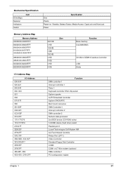
Mechanical Specification Drive Bays Material Indicators Switch Item Specification One Plastic Power-on, Standby, Battery Status, Media Access, CapsLock and NumLock Power Memory Address Map Memory Address 00000000-0009FFFF 80600000-80600FFF 80620000-8063FFFF 81000000-81FFFFF 000A0000-000CFFFF 08000000-08000FFF 08001000-...
Mechanical Specification Drive Bays Material Indicators Switch Item Specification One Plastic Power-on, Standby, Battery Status, Media Access, CapsLock and NumLock Power Memory Address Map Memory Address 00000000-0009FFFF 80600000-80600FFF 80620000-8063FFFF 81000000-81FFFFF 000A0000-000CFFFF 08000000-08000FFF 08001000-...

TravelMate 220 Service Guide
Page 54
... first remove the keyboard, then disassemble the inside assembly frame in that need to remove the main board, you on the components that order. START Battery Bx1 Modem Cover Bx2 CD-ROM Module Ex4 Left & Right Hinge Caps Modem Board CD-Rom Drive Jx2 CD-ROM Transfer Board CD-ROM Drive...
... first remove the keyboard, then disassemble the inside assembly frame in that need to remove the main board, you on the components that order. START Battery Bx1 Modem Cover Bx2 CD-ROM Module Ex4 Left & Right Hinge Caps Modem Board CD-Rom Drive Jx2 CD-ROM Transfer Board CD-ROM Drive...

TravelMate 220 Service Guide
Page 55
Main Unit LCD Module Dx2 CPU Heat Sink Plate Touch Pad Frame RTC Battery Bx1 Ax8 Upper Case Touch Pad Frame W/ Touch Pad Button Touch Pad Board Touch Pad FPC Touch Pad Scroll Key Kx4 CPU Heat Sink Gx1 CPU Fan Hx1 Charger Plate Fx1 Audio Board Modem Board Hx2 Fx1 Main Board Bx4 PCMCIA Plate RTC Battery Holder FDD Module Bx2 FDD FDD Bracket FDD FPC FDD Bezel PCMCIA Slot Ix6 I/O Port Bracket Modem Cable 46 Chapter 3
Main Unit LCD Module Dx2 CPU Heat Sink Plate Touch Pad Frame RTC Battery Bx1 Ax8 Upper Case Touch Pad Frame W/ Touch Pad Button Touch Pad Board Touch Pad FPC Touch Pad Scroll Key Kx4 CPU Heat Sink Gx1 CPU Fan Hx1 Charger Plate Fx1 Audio Board Modem Board Hx2 Fx1 Main Board Bx4 PCMCIA Plate RTC Battery Holder FDD Module Bx2 FDD FDD Bracket FDD FPC FDD Bezel PCMCIA Slot Ix6 I/O Port Bracket Modem Cable 46 Chapter 3

TravelMate 220 Service Guide
Page 57
To remove the battery pack, push the battery release button inward then slide the battery pack out from the machine. Removing the Battery Cover 1. Removing the Battery Pack 1. To remove the battery cover, press the cover side outward carefully then remove the cover. 48 Chapter 3
To remove the battery pack, push the battery release button inward then slide the battery pack out from the machine. Removing the Battery Cover 1. Removing the Battery Pack 1. To remove the battery cover, press the cover side outward carefully then remove the cover. 48 Chapter 3

TravelMate 220 Service Guide
Page 58
Remove the CD-ROM drive module from the machine. Slide it out from the CD-ROM drive chassis. To disassemble the CD-ROM drive module, first remove four screws as shown. 3. Removing the CD-ROM Drive Module 1. To remove the CD-ROM drive module, push the release button outward. 3. Disassembling the CD-ROM Drive Module 1. Chapter 3 49 See "Removing the Battery Pack" on page 49 2. See "Removing the Battery Pack" on page 49 2.
Remove the CD-ROM drive module from the machine. Slide it out from the CD-ROM drive chassis. To disassemble the CD-ROM drive module, first remove four screws as shown. 3. Removing the CD-ROM Drive Module 1. To remove the CD-ROM drive module, push the release button outward. 3. Disassembling the CD-ROM Drive Module 1. Chapter 3 49 See "Removing the Battery Pack" on page 49 2. See "Removing the Battery Pack" on page 49 2.

TravelMate 220 Service Guide
Page 60
To remove the hard disk drive, first remove the hard disk drive cover screw, then remove the cover. 3. Disassembling the Hard Disk Drive Module 1. See "Removing the Battery Pack" on page 49 2. See "Removing the Battery Pack" on page 49 2. Remove the gasket from the hard disk drive bracket. 4. To disassemble the hard disk drive module, first remove the two screws from the hard disk drive module. Chapter 3 51 Remove the hard disk drive module out from the machine carefully. See "Removing the Hard Disk Drive Module" on page 52 3. Removing the Hard Disk Drive Module 1.
To remove the hard disk drive, first remove the hard disk drive cover screw, then remove the cover. 3. Disassembling the Hard Disk Drive Module 1. See "Removing the Battery Pack" on page 49 2. See "Removing the Battery Pack" on page 49 2. Remove the gasket from the hard disk drive bracket. 4. To disassemble the hard disk drive module, first remove the two screws from the hard disk drive module. Chapter 3 51 Remove the hard disk drive module out from the machine carefully. See "Removing the Hard Disk Drive Module" on page 52 3. Removing the Hard Disk Drive Module 1.

TravelMate 220 Service Guide
Page 62
Push the memory cover leftward to lift the cover off, then remove the memory cover. 4. To remove the Extended memory from the machine, first remove the screw from the socket. Removing the Extended Memory 1. See "Removing the Battery Pack" on both sides of the socket and pull the memory module out from the memory cover. 3. Push out the latches on page 49 2. Chapter 3 53
Push the memory cover leftward to lift the cover off, then remove the memory cover. 4. To remove the Extended memory from the machine, first remove the screw from the socket. Removing the Extended Memory 1. See "Removing the Battery Pack" on both sides of the socket and pull the memory module out from the memory cover. 3. Push out the latches on page 49 2. Chapter 3 53

TravelMate 220 Service Guide
Page 63
Remove the modem cover from the main unit carefully by using a plastic bladed screw driver. 5. Remove two screws from the modem board as shown, then remove the modem board from the machine. 4. To remove the modem board, first remove the screw from the modem board, then remove the modem board. 54 Chapter 3 Removing the Modem Boar 1. Disconnect the modem cable from the modem cover. 3. See "Removing the Battery Pack" on page 49 2.
Remove the modem cover from the main unit carefully by using a plastic bladed screw driver. 5. Remove two screws from the modem board as shown, then remove the modem board from the machine. 4. To remove the modem board, first remove the screw from the modem board, then remove the modem board. 54 Chapter 3 Removing the Modem Boar 1. Disconnect the modem cable from the modem cover. 3. See "Removing the Battery Pack" on page 49 2.

TravelMate 220 Service Guide
Page 64
...slide the hinge caps out from the launch board. See "Removing the Hinge Caps" on page 49 2. Removing the Middle Cover 1. See "Removing the Battery Pack" on page 56 3. Removing the Launch Board 1. See "Removing the Middle Cover" on page 49 2. Disassembling the LCD Removing the Hinge Caps ...1. See "Removing the Battery Pack" on page 56 4. Chapter 3 55 See "Removing the Hinge Caps" on page 49 2. Disconnect the launch board cable from the main unit....
...slide the hinge caps out from the launch board. See "Removing the Hinge Caps" on page 49 2. Removing the Middle Cover 1. See "Removing the Battery Pack" on page 56 3. Removing the Launch Board 1. See "Removing the Middle Cover" on page 49 2. Disassembling the LCD Removing the Hinge Caps ...1. See "Removing the Battery Pack" on page 56 4. Chapter 3 55 See "Removing the Hinge Caps" on page 49 2. Disconnect the launch board cable from the main unit....


