
User Manual
Page 3
... uneven brightness on the screen depending on the product. Keep this case, the screen is displayed for a few hours. It may remain after switching the image, when the same image is recovered slowly by changing the image or turning off the power switch and then turn it on again to the nature of 0.01% or less such as a missing pixel or a pixel lit all warnings and instructions...
... uneven brightness on the screen depending on the product. Keep this case, the screen is displayed for a few hours. It may remain after switching the image, when the same image is recovered slowly by changing the image or turning off the power switch and then turn it on again to the nature of 0.01% or less such as a missing pixel or a pixel lit all warnings and instructions...
User Manual
Page 4
... noisy surroundings. • Turn the volume down if you can hear it clearly and comfortably and without distortion. • After setting the volume level, do not place the product on a vibrating surface. • Never use this monitor ,do not be used with this product, make sure that could be blocked or covered. When you plug the power cord into this product on...
... noisy surroundings. • Turn the volume down if you can hear it clearly and comfortably and without distortion. • After setting the volume level, do not place the product on a vibrating surface. • Never use this monitor ,do not be used with this product, make sure that could be blocked or covered. When you plug the power cord into this product on...

User Manual
Page 5
... with the supplied power supply cord set , make sure that the total rating of all servicing to replace the power cord set . Also, make sure that is a safety feature. Do not insert the plug into the extension cord does not exceed the extension cord ampere rating. The grounding pin is not properly grounded may expose you need for details. v ampere rating of the equipment plugged into a non-grounded power outlet. Using a power outlet...
... with the supplied power supply cord set , make sure that the total rating of all servicing to replace the power cord set . Also, make sure that is a safety feature. Do not insert the plug into the extension cord does not exceed the extension cord ampere rating. The grounding pin is not properly grounded may expose you need for details. v ampere rating of the equipment plugged into a non-grounded power outlet. Using a power outlet...

User Manual
Page 6
... damage and will often require extensive work by the operating instructions, since improper adjustment of radio equipment in fuel depots, storage and distribution areas; IT Equipment Recycling Information Acer is strongly committed to normal condition. We at service stations. To minimize pollution and ensure utmost protection of small children. Switch off your device in any area...
... damage and will often require extensive work by the operating instructions, since improper adjustment of radio equipment in fuel depots, storage and distribution areas; IT Equipment Recycling Information Acer is strongly committed to normal condition. We at service stations. To minimize pollution and ensure utmost protection of small children. Switch off your device in any area...
User Manual
Page 7
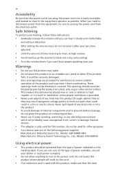
... in one fixed posture • avoid slouching forward and/or leaning backward • stand up and walk around regularly to carpal tunnel syndrome, tendonitis, tenosynovitis or other factors greatly increase the risk of the monitor, using a footrest, or raising your company's health and safety department. The following tips: • refrain from Sleep mode by adjusting the viewing angle...
... in one fixed posture • avoid slouching forward and/or leaning backward • stand up and walk around regularly to carpal tunnel syndrome, tendonitis, tenosynovitis or other factors greatly increase the risk of the monitor, using a footrest, or raising your company's health and safety department. The following tips: • refrain from Sleep mode by adjusting the viewing angle...

User Manual
Page 8
... point. • Blink frequently to an awkward viewing angle. • Avoid looking at bright light sources, such as open windows, for enhanced text readability and graphics clarity. • Eliminate glare and reflections by: • placing your display in such a way that the side faces the window or any light source • minimizing room light by looking away from the monitor and focusing on...
... point. • Blink frequently to an awkward viewing angle. • Avoid looking at bright light sources, such as open windows, for enhanced text readability and graphics clarity. • Eliminate glare and reflections by: • placing your display in such a way that the side faces the window or any light source • minimizing room light by looking away from the monitor and focusing on...
User Manual
Page 9
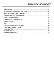
TABLE OF CONTENTS UNPACKING 1 ATTACHING / REMOVING THE BASE 2 SCREEN POSITION ADJUSTMENT 2 CONNECTING THE POWER CORD 3 SAFETY PRECAUTION 3 CLEANING YOUR MONITOR 3 POWER SAVING 4 DDC...4 CONNECTOR PIN ASSIGNMENT 5 STANDARD TIMING TABLE 9 INSTALLATION 10 USER CONTROLS 11 TROUBLESHOOTING 17
TABLE OF CONTENTS UNPACKING 1 ATTACHING / REMOVING THE BASE 2 SCREEN POSITION ADJUSTMENT 2 CONNECTING THE POWER CORD 3 SAFETY PRECAUTION 3 CLEANING YOUR MONITOR 3 POWER SAVING 4 DDC...4 CONNECTOR PIN ASSIGNMENT 5 STANDARD TIMING TABLE 9 INSTALLATION 10 USER CONTROLS 11 TROUBLESHOOTING 17
User Manual
Page 11
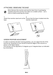
... using both of your hands to 15 degrees up or 5 degrees down on a stable surface -- monitor stand arm. SCREEN POSITION ADJUSTMENT In order to optimize the best viewing position, you can be adjusted to hold the edges of the monitor by arrow below . Carefully place the monitor face-down as shown in the figure below . 5°-15° EN-2 ATTACHING / REMOVING THE BASE Note: Remove the monitor...
... using both of your hands to 15 degrees up or 5 degrees down on a stable surface -- monitor stand arm. SCREEN POSITION ADJUSTMENT In order to optimize the best viewing position, you can be adjusted to hold the edges of the monitor by arrow below . Carefully place the monitor face-down as shown in the figure below . 5°-15° EN-2 ATTACHING / REMOVING THE BASE Note: Remove the monitor...
User Manual
Page 12
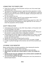
... or openings of H05VV-F cord and plug rated 10 A, 250 V. Always put the monitor in which the equipment will not be installed. CONNECTING THE POWER CORD Check first to wipe the screen and cabinet front and sides. NEVER SPRAY OR POUR ANY LIQUID DIRECTLY ONTO THE SCREEN OR CASE. PLEASE DO NOT USE ANY AMMONIA OR ALCOHOL-BASED CLEANERS ON THE LCD DISPLAY SCREEN...
... or openings of H05VV-F cord and plug rated 10 A, 250 V. Always put the monitor in which the equipment will not be installed. CONNECTING THE POWER CORD Check first to wipe the screen and cabinet front and sides. NEVER SPRAY OR POUR ANY LIQUID DIRECTLY ONTO THE SCREEN OR CASE. PLEASE DO NOT USE ANY AMMONIA OR ALCOHOL-BASED CLEANERS ON THE LCD DISPLAY SCREEN...
User Manual
Page 13
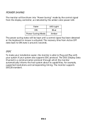
...-4 The DDC (Display Data Channel) is activated. State ON Power Saving Mode LED Light Blue Amber The power saving states will be kept until a control signal has been detected or the keyboard or mouse is a communication protocol through which the monitor automatically informs the host system about its capabilities, for example, supported resolutions and corresponding timing. POWER SAVING The monitor will be driven into "Power Saving" mode by the amber-color power LED.
...-4 The DDC (Display Data Channel) is activated. State ON Power Saving Mode LED Light Blue Amber The power saving states will be kept until a control signal has been detected or the keyboard or mouse is a communication protocol through which the monitor automatically informs the host system about its capabilities, for example, supported resolutions and corresponding timing. POWER SAVING The monitor will be driven into "Power Saving" mode by the amber-color power LED.

User Manual
Page 14
TMDS Data2- 13. NC 2. NC 16. DDC Clock 18. TMDS Data 0/5 Shield 8. DDC TMDS Clock- * only for certain models EN-5 TMDS Data0- 6. NC 9. TMDS Data 1/3 Shield 23. Logic Ground 4. DDC Data 19. Hot Plug Detect 5. NC 20. NC 10. TMDS Clock Shield 11. TMDS Clock+ 12. NC 24. TMDS Data 2/4 Shield 15. CONNECTOR PIN ASSIGNMENT 24-Pin Color Display Signal Cable* PIN Meaning PIN Meaning 1. TMDS Data0+ 7. TMDS Data1+ 22. TMDS Data2+ 14. +5V Power 3. NC 17. TMDS Data1- 21.
TMDS Data2- 13. NC 2. NC 16. DDC Clock 18. TMDS Data 0/5 Shield 8. DDC TMDS Clock- * only for certain models EN-5 TMDS Data0- 6. NC 9. TMDS Data 1/3 Shield 23. Logic Ground 4. DDC Data 19. Hot Plug Detect 5. NC 20. NC 10. TMDS Clock Shield 11. TMDS Clock+ 12. NC 24. TMDS Data 2/4 Shield 15. CONNECTOR PIN ASSIGNMENT 24-Pin Color Display Signal Cable* PIN Meaning PIN Meaning 1. TMDS Data0+ 7. TMDS Data1+ 22. TMDS Data2+ 14. +5V Power 3. NC 17. TMDS Data1- 21.

User Manual
Page 15
TMDS Data0 Shield 9. TMDS Clock- 13. Reserved (N.C. SDA 17. CEC 14. TMDS Data0- * only for certain models PIN Meaning 10. TMDS Clock Shield 12. SCL 16. TMDS Data1 Shield 6. TMDS Data1+ 5. TMDS Data2 Shield 3. on device) 15. TMDS Clock+ 11. TMDS Data2+ 2. Hot Plug Detect EN-6 TMDS Data1- 7. 19-Pin Color Display Signal Cable* PIN Meaning 1. TMDS Data2- 4. TMDS Data0+ 8. DDC/CEC Ground 18. +5V Power 19.
TMDS Data0 Shield 9. TMDS Clock- 13. Reserved (N.C. SDA 17. CEC 14. TMDS Data0- * only for certain models PIN Meaning 10. TMDS Clock Shield 12. SCL 16. TMDS Data1 Shield 6. TMDS Data1+ 5. TMDS Data2 Shield 3. on device) 15. TMDS Clock+ 11. TMDS Data2+ 2. Hot Plug Detect EN-6 TMDS Data1- 7. 19-Pin Color Display Signal Cable* PIN Meaning 1. TMDS Data2- 4. TMDS Data0+ 8. DDC/CEC Ground 18. +5V Power 19.

User Manual
Page 17
Lane1(p) 5. GND 9. Lane3(p) * only for certain models PIN Description 11. AUX_CH (n) 16. GND 12. Lane2(p) 8. Lane3(n) 13. Config2 15. Lane0(n) 4. GND 6. Hot Plug Detect 19. DP Power_Return 20. Config1 14. AUX_CH (p) 18. GND 3. GND 17. DP Power EN-8 Lane0(p) 2. Lane1(n) 7. 20-Pin Color Display Signal Cable* PIN Description 1. Lane3(n) 10.
Lane1(p) 5. GND 9. Lane3(p) * only for certain models PIN Description 11. AUX_CH (n) 16. GND 12. Lane2(p) 8. Lane3(n) 13. Config2 15. Lane0(n) 4. GND 6. Hot Plug Detect 19. DP Power_Return 20. Config1 14. AUX_CH (p) 18. GND 3. GND 17. DP Power EN-8 Lane0(p) 2. Lane1(n) 7. 20-Pin Color Display Signal Cable* PIN Description 1. Lane3(n) 10.
User Manual
Page 19
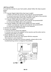
... computer are powered-OFF. b. Make sure both the monitor and computer are powered-OFF. Connect one end of the monitor and connect the other end to the adapter. Connect one end of the 24-pin DVI cable to the back of the adapter to the monitor and the other end to the computer's port. 1-2 Connect HDMI Cable (Only HDMI-input model) a. INSTALLATION To install the monitor to diagnose the problem. Connect the AC cord to a properly...
... computer are powered-OFF. b. Make sure both the monitor and computer are powered-OFF. Connect one end of the monitor and connect the other end to the adapter. Connect one end of the 24-pin DVI cable to the back of the adapter to the monitor and the other end to the computer's port. 1-2 Connect HDMI Cable (Only HDMI-input model) a. INSTALLATION To install the monitor to diagnose the problem. Connect the AC cord to a properly...
User Manual
Page 20
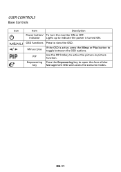
Lights up to indicate the power is active, press the Minus or Plus button to open the Acer eColor Management OSD and access the scenario modes. Minus / plus PIP Empowering key If the OSD is turned ON. EN-11 OSD functions Press to active the picture-in-picture function. Use the PIP hotkey to view the OSD. Press the Empowering key to toggle between the OSD options. USER CONTROLS Base Controls Icon / Item Power button/ indicator Description To turn the monitor ON or OFF.
Lights up to indicate the power is active, press the Minus or Plus button to open the Acer eColor Management OSD and access the scenario modes. Minus / plus PIP Empowering key If the OSD is turned ON. EN-11 OSD functions Press to active the picture-in-picture function. Use the PIP hotkey to view the OSD. Press the Empowering key to toggle between the OSD options. USER CONTROLS Base Controls Icon / Item Power button/ indicator Description To turn the monitor ON or OFF.

User Manual
Page 21
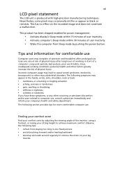
Acer eColor Management Operation instructions Step 1: Press " " Key to open the Acer eColor Management OSD and access the scenario modes Step 2: Press "" or "" to reduce power consumption. N/A Standard Default Setting. N/A Movie mode Displays scenes in vibrant colors with sharp detail. Pictures and photographs appear in clearest detail. Reflects native display mode capability N/A Graphic mode Enhances colors and emphasize fine detail. Presents great visuals, even in unsuitably-lit...
Acer eColor Management Operation instructions Step 1: Press " " Key to open the Acer eColor Management OSD and access the scenario modes Step 2: Press "" or "" to reduce power consumption. N/A Standard Default Setting. N/A Movie mode Displays scenes in vibrant colors with sharp detail. Pictures and photographs appear in clearest detail. Reflects native display mode capability N/A Graphic mode Enhances colors and emphasize fine detail. Presents great visuals, even in unsuitably-lit...
User Manual
Page 22
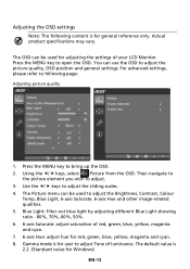
... adjust the sliding scales. 4. Using the / keys, select Picture from the OSD. The Picture menu can use the OSD to adjust the Brightness, Contrast, Colour Temp, Blue Light, 6-axis Saturate, 6-axis Hue and other image-related qualities. 5. You can be used to adjust the picture quality, OSD position and general settings. Use the / keys to open the OSD. The default value is for adjusting the settings of your LCD Monitor. Blue Light: filter out blue light by adjusting different Blue Light...
... adjust the sliding scales. 4. Using the / keys, select Picture from the OSD. The Picture menu can use the OSD to adjust the Brightness, Contrast, Colour Temp, Blue Light, 6-axis Saturate, 6-axis Hue and other image-related qualities. 5. You can be used to adjust the picture quality, OSD position and general settings. Use the / keys to open the OSD. The default value is for adjusting the settings of your LCD Monitor. Blue Light: filter out blue light by adjusting different Blue Light...

User Manual
Page 23
It can simulate high-resolution images by boosting the pixel density of the original source. Adjusting OSD settings 1. Using the directional keys, select OSD from the on screen display. EN-14 9. Then navigate to the feature you wish to bring up the OSD. 2. Super Sharpness technology can make images sharper and clear. 10. Press the MENU key to adjust. sRGB mode is for user such as DSCs, printers, photographer to get better color matching representation with the peripheral device.
It can simulate high-resolution images by boosting the pixel density of the original source. Adjusting OSD settings 1. Using the directional keys, select OSD from the on screen display. EN-14 9. Then navigate to the feature you wish to bring up the OSD. 2. Super Sharpness technology can make images sharper and clear. 10. Press the MENU key to adjust. sRGB mode is for user such as DSCs, printers, photographer to get better color matching representation with the peripheral device.

User Manual
Page 24
Adjusting miscellaneous settings 1. The setting menu can be selected manually. PIP On & Input Status PIP Main DVI HDMI DP Mini-DP DVI O O O O HDMI O O O O DP O O O X Mini-DP O O X O X: Does not support PIP function in -picture settings. "Wide mode" is not supported when using PIP/PBP, "Wide mode", "6-axis Saturate", "6-axis Hue", "ACM", "Gamma", "sRGB", and "Super Sharpness" will be enabled for PIP. The PIP signal source needs to be used to adjust picture-in this combination 5. EN-15...
Adjusting miscellaneous settings 1. The setting menu can be selected manually. PIP On & Input Status PIP Main DVI HDMI DP Mini-DP DVI O O O O HDMI O O O O DP O O O X Mini-DP O O X O X: Does not support PIP function in -picture settings. "Wide mode" is not supported when using PIP/PBP, "Wide mode", "6-axis Saturate", "6-axis Hue", "ACM", "Gamma", "sRGB", and "Super Sharpness" will be enabled for PIP. The PIP signal source needs to be used to adjust picture-in this combination 5. EN-15...
User Manual
Page 26
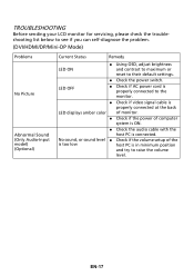
... self-diagnose the problem. (DVI/HDMI/DP/Mini-DP Mode) Problems No Picture Abnormal Sound (Only Audio-Input model) (Optional) Current Status Remedy LED ON Using OSD, adjust brightness and contrast to maximum or reset to the monitor. Check if video signal cable is properly connected at the back LED displays amber color of monitor. Check if the power of the is too low host PC is connected. No sound, or sound level Check if the volume setup of computer system...
... self-diagnose the problem. (DVI/HDMI/DP/Mini-DP Mode) Problems No Picture Abnormal Sound (Only Audio-Input model) (Optional) Current Status Remedy LED ON Using OSD, adjust brightness and contrast to maximum or reset to the monitor. Check if video signal cable is properly connected at the back LED displays amber color of monitor. Check if the power of the is too low host PC is connected. No sound, or sound level Check if the volume setup of computer system...


