
ErP Energy-related Product directive technical document
Page 1
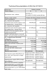
Technical Documentation of (EU) No 617/2013 Product type Product category Desktop computer B D Manufacturer name, address Acer Italy s.r.l, Via Lepetit, 40, 20020 Lainate (MI) Italy Product model number Year of manufacture Predator G6-720 B Predator G6-720 D 2017 ETEC allowance with capability adjustments when discrete graphics cards are disabled (from 1 January 2016) 199 kWh/year 235 kWh/year ETEC allowance with capability adjustments when discrete graphics cards 321...
Technical Documentation of (EU) No 617/2013 Product type Product category Desktop computer B D Manufacturer name, address Acer Italy s.r.l, Via Lepetit, 40, 20020 Lainate (MI) Italy Product model number Year of manufacture Predator G6-720 B Predator G6-720 D 2017 ETEC allowance with capability adjustments when discrete graphics cards are disabled (from 1 January 2016) 199 kWh/year 235 kWh/year ETEC allowance with capability adjustments when discrete graphics cards 321...
ErP Energy-related Product directive technical document
Page 2
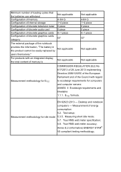
... mode; 5.7. ETEC formula. Test setup; True RMS watt meter specification; 5.8. Minimum number of loading cycles that the batteries can withstand Configuration of memory Not applicable 4~64 G Configuration of internal storage 1~4 piece Configuration of discrete television tuner 0 piece Configuration of discrete audio card 0 piece Configuration of discrete graphics cards Configuration of discrete graphics cards category 0~1 piece G7 The external package of the Council with regard to ecodesign requirements for computers and computer servers...
... mode; 5.7. ETEC formula. Test setup; True RMS watt meter specification; 5.8. Minimum number of loading cycles that the batteries can withstand Configuration of memory Not applicable 4~64 G Configuration of internal storage 1~4 piece Configuration of discrete television tuner 0 piece Configuration of discrete audio card 0 piece Configuration of discrete graphics cards Configuration of discrete graphics cards category 0~1 piece G7 The external package of the Council with regard to ecodesign requirements for computers and computer servers...
ErP Energy-related Product directive technical document
Page 5
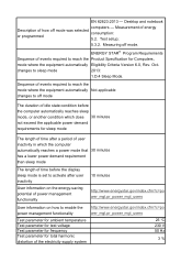
... display sleep mode is set to activate after user inactivity User information on the energy-saving potential of power management functionality 10 minutes http://www.energystar.gov/index.cfm?c=po wer_mgt.pr_power_mgt_users User information on how to enable the power management functionality Test parameter for ambient temperature Test parameter for test voltage Test parameter for frequency Test parameter for total harmonic distortion of events required to sleep mode 2013: 1.D.4 Sleep Mode...
... display sleep mode is set to activate after user inactivity User information on the energy-saving potential of power management functionality 10 minutes http://www.energystar.gov/index.cfm?c=po wer_mgt.pr_power_mgt_users User information on how to enable the power management functionality Test parameter for ambient temperature Test parameter for test voltage Test parameter for frequency Test parameter for total harmonic distortion of events required to sleep mode 2013: 1.D.4 Sleep Mode...

User Manual
Page 3
...-installation instructions 6 System covers 7 Removing the rear system cover 7 Installing the rear system cover 8 Removing the left side system cover .......... 9 Installing the left side system cover .......... 10 Hard drives 11 Removing the 3.5-inch Easy Swap hard drive 11 Installing the 3.5-inch Easy Swap hard drive 14 Removing the 3.5-inch hard drives 16 Installing the 3.5-inch hard drives 21 Memory 26 Memory configuration guidelines 26 Removing a memory module 27 Installing a memory module 29 Graphics board 32 Removing the graphics board 32 Installing the graphics...
...-installation instructions 6 System covers 7 Removing the rear system cover 7 Installing the rear system cover 8 Removing the left side system cover .......... 9 Installing the left side system cover .......... 10 Hard drives 11 Removing the 3.5-inch Easy Swap hard drive 11 Installing the 3.5-inch Easy Swap hard drive 14 Removing the 3.5-inch hard drives 16 Installing the 3.5-inch hard drives 21 Memory 26 Memory configuration guidelines 26 Removing a memory module 27 Installing a memory module 29 Graphics board 32 Removing the graphics board 32 Installing the graphics...

User Manual
Page 5
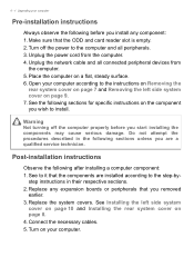
... replacement process, you install a computer component: 1. During the disassembly process, group the screws with pre-installation and post-installation instructions. Do not remove a component from its protective packaging until you read the following tools: • Philips screwdriver • Hex screwdriver • Flat screwdriver • Scissors Note The screws for the different components vary in size. 1 Upgrading your processor, disk drives, expansion boards...
... replacement process, you install a computer component: 1. During the disassembly process, group the screws with pre-installation and post-installation instructions. Do not remove a component from its protective packaging until you read the following tools: • Philips screwdriver • Hex screwdriver • Flat screwdriver • Scissors Note The screws for the different components vary in size. 1 Upgrading your processor, disk drives, expansion boards...
User Manual
Page 6
... Removing the rear system cover on page 7 and Removing the left side system cover on page 10 and Installing the rear system cover on page 8. 4. See to the computer and all connected peripheral devices from the computer. 4. Turn off the computer properly before you start installing the components may cause serious damage. Unplug the network cable and all peripherals. 3. step instructions in the following sections for specific instructions...
... Removing the rear system cover on page 7 and Removing the left side system cover on page 10 and Installing the rear system cover on page 8. 4. See to the computer and all connected peripheral devices from the computer. 4. Turn off the computer properly before you start installing the components may cause serious damage. Unplug the network cable and all peripherals. 3. step instructions in the following sections for specific instructions...
User Manual
Page 7
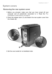
Read the Preinstallation instructions on page 6. 2. Press the release latch (1) and detach the rear system cover from the chassis (2). 3. Set the cover aside for re-installation later. System covers 1 Upgrading your computer and all peripherals connected to it. Before you proceed, make sure that you have turned off your computer - 7 Removing the rear system cover 1.
Read the Preinstallation instructions on page 6. 2. Press the release latch (1) and detach the rear system cover from the chassis (2). 3. Set the cover aside for re-installation later. System covers 1 Upgrading your computer and all peripherals connected to it. Before you proceed, make sure that you have turned off your computer - 7 Removing the rear system cover 1.
User Manual
Page 9
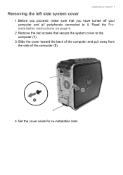
1 Upgrading your computer and all peripherals connected to the computer (1). 3. Before you have turned off your computer - 9 Removing the left side system cover 1. Remove the two screws that you proceed, make sure that secure the system cover to it. Read the Preinstallation instructions on page 6. 2. Set the cover aside for re-installation later. Slide the cover toward the back of the computer and pull away from the side of the computer (2). 4.
1 Upgrading your computer and all peripherals connected to the computer (1). 3. Before you have turned off your computer - 9 Removing the left side system cover 1. Remove the two screws that you proceed, make sure that secure the system cover to it. Read the Preinstallation instructions on page 6. 2. Set the cover aside for re-installation later. Slide the cover toward the back of the computer and pull away from the side of the computer (2). 4.

User Manual
Page 11
Perform Pre-installation instructions on page 6. 2. Press the expansion bay cover to gain access to the easy swap hard drive. 1 Upgrading your computer - 11 Hard drives The computer supports installation of one 3.5-inch SATA hard drive in the Easy Swap Expansion Bay and two 3.5-inch SATA hard drives in the internal HDD cage. Removing the 3.5-inch Easy Swap hard drive 1.
Perform Pre-installation instructions on page 6. 2. Press the expansion bay cover to gain access to the easy swap hard drive. 1 Upgrading your computer - 11 Hard drives The computer supports installation of one 3.5-inch SATA hard drive in the Easy Swap Expansion Bay and two 3.5-inch SATA hard drives in the internal HDD cage. Removing the 3.5-inch Easy Swap hard drive 1.

User Manual
Page 14
Place the hard drive into the carrier (1) and reinsert the retaining screws into the expansion bay. 14 - 1 Upgrading your computer Installing the 3.5-inch Easy Swap hard drive 1. Slide the hard drive into the hard drive (2). 3. Remove the new hard drive from its packaging. 2.
Place the hard drive into the carrier (1) and reinsert the retaining screws into the expansion bay. 14 - 1 Upgrading your computer Installing the 3.5-inch Easy Swap hard drive 1. Slide the hard drive into the hard drive (2). 3. Remove the new hard drive from its packaging. 2.

User Manual
Page 16
Use a long screw driver to loosen the four captive screws securing the thermal module to the mainboard. 16 - 1 Upgrading your computer Removing the 3.5-inch hard drives 1. Disconnect the thermal fan cable from the mainboard. 3. Perform Pre-installation instructions on page 6. 2.
Use a long screw driver to loosen the four captive screws securing the thermal module to the mainboard. 16 - 1 Upgrading your computer Removing the 3.5-inch hard drives 1. Disconnect the thermal fan cable from the mainboard. 3. Perform Pre-installation instructions on page 6. 2.

User Manual
Page 18
Remove the three screws that secure the HDD bracket to the chassis. 18 - 1 Upgrading your computer 6. Disconnect the power and data cables from the hard drives. 7.
Remove the three screws that secure the HDD bracket to the chassis. 18 - 1 Upgrading your computer 6. Disconnect the power and data cables from the hard drives. 7.

User Manual
Page 21
Remove the new hard drives from their packaging. 2. Secure the new hard drives with eight screws. 1 Upgrading your computer - 21 Installing the 3.5-inch hard drives 1. Insert the new hard drives into the bracket. 3.
Remove the new hard drives from their packaging. 2. Secure the new hard drives with eight screws. 1 Upgrading your computer - 21 Installing the 3.5-inch hard drives 1. Insert the new hard drives into the bracket. 3.

User Manual
Page 23
Connect the power and data cables to secure the cables. Use the cable clip to the hard drives. 7. 1 Upgrading your computer - 23 6.
Connect the power and data cables to secure the cables. Use the cable clip to the hard drives. 7. 1 Upgrading your computer - 23 6.
User Manual
Page 26
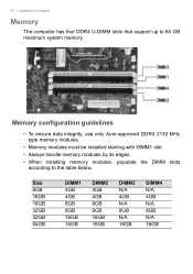
... N/A 16GB Memory configuration guidelines • To ensure data integrity, use only Acer-approved DDR4 2133 MHz type memory modules. • Memory modules must be installed starting with DIMM1 slot. • Always handle memory modules by its edges. • When installing memory modules, populate the DIMM slots according to 64 GB maximum system memory. 26 - 1 Upgrading your computer Memory The computer has four DDR4 U-DIMM slots that support up to...
... N/A 16GB Memory configuration guidelines • To ensure data integrity, use only Acer-approved DDR4 2133 MHz type memory modules. • Memory modules must be installed starting with DIMM1 slot. • Always handle memory modules by its edges. • When installing memory modules, populate the DIMM slots according to 64 GB maximum system memory. 26 - 1 Upgrading your computer Memory The computer has four DDR4 U-DIMM slots that support up to...

User Manual
Page 27
Disconnect the thermal fan cable from the mainboard. 3. Use a long screw driver to loosen the four captive screws securing the thermal module to the mainboard. 1 Upgrading your computer - 27 Removing a memory module 1. Perform Pre-installation instructions on page 6. 2.
Disconnect the thermal fan cable from the mainboard. 3. Use a long screw driver to loosen the four captive screws securing the thermal module to the mainboard. 1 Upgrading your computer - 27 Removing a memory module 1. Perform Pre-installation instructions on page 6. 2.

User Manual
Page 32
Removing the graphics board 1. Perform Pre-installation instructions on page 6. 2. Disconnect the power cables from the graphics board. 32 - 1 Upgrading your computer Graphics board The computer contains one graphics board installed in the PCIe x16 slot.
Removing the graphics board 1. Perform Pre-installation instructions on page 6. 2. Disconnect the power cables from the graphics board. 32 - 1 Upgrading your computer Graphics board The computer contains one graphics board installed in the PCIe x16 slot.

User Manual
Page 37
Remove the graphics board. 1 Upgrading your computer - 37 SSD module The computer contains one SSD module installed in the mini-PCIe slot. Remove the screw that secures the SSD module to the mainboard. Removing the SSD module 1. Perform Pre-installation instructions on page 32. 3. See Removing the graphics board on page 6. 2.
Remove the graphics board. 1 Upgrading your computer - 37 SSD module The computer contains one SSD module installed in the mini-PCIe slot. Remove the screw that secures the SSD module to the mainboard. Removing the SSD module 1. Perform Pre-installation instructions on page 32. 3. See Removing the graphics board on page 6. 2.
User Manual
Page 41
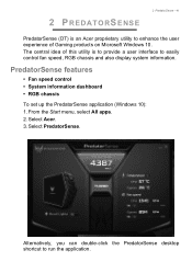
... chassis To set up the PredatorSense application (Windows 10): 1. 2 PREDATORSENSE 2 PredatorSense - 41 PredatorSense (DT) is to provide a user interface to easily control fan speed, RGB chassis and also display system information. The central idea of this utility is an Acer proprietary utility to run the application. Select Acer. 3. From the Start menu, select All apps. 2. Alternatively, you can double-click the PredatorSense desktop shortcut to...
... chassis To set up the PredatorSense application (Windows 10): 1. 2 PREDATORSENSE 2 PredatorSense - 41 PredatorSense (DT) is to provide a user interface to easily control fan speed, RGB chassis and also display system information. The central idea of this utility is an Acer proprietary utility to run the application. Select Acer. 3. From the Start menu, select All apps. 2. Alternatively, you can double-click the PredatorSense desktop shortcut to...

User Manual
Page 42
... turn on when CPU speed is enabled. 42 - 2 PredatorSense Category CPU frequency Temperature CPU System Fan Speed CPU System Growl Lights CPU Speed Setting Turbo Description Shows CPU frequency information in RPM. The LED lights on both side panels will automatically turn on if Growl Lights is set to turbo (over clock). The turbo function can also be enabled or disabled using the TURBO button located at the top of System fan. Configures the CPU speed settings with below option: Sets the CPU speed...
... turn on when CPU speed is enabled. 42 - 2 PredatorSense Category CPU frequency Temperature CPU System Fan Speed CPU System Growl Lights CPU Speed Setting Turbo Description Shows CPU frequency information in RPM. The LED lights on both side panels will automatically turn on if Growl Lights is set to turbo (over clock). The turbo function can also be enabled or disabled using the TURBO button located at the top of System fan. Configures the CPU speed settings with below option: Sets the CPU speed...


