

User Manual
Page 3
... Removing a memory module 18 Installing a memory module 19 Graphic board 20 Removing the Graphic board 20 Installing the Graphic board 23 M.2 SSD module 25 Removing the M.2 SSD module............25 Installing the M.2 SSD module 27 ODD drives 29 Open ODD door 29 Hard swap HDD 30 Dust filter 33 Removing the Dust filter from Front Bezel 33 Removing the Dust filter from Power Cover 34 Removing the Front Bezel 35 ARGB Control PCB 36 About LED Number...
... Removing a memory module 18 Installing a memory module 19 Graphic board 20 Removing the Graphic board 20 Installing the Graphic board 23 M.2 SSD module 25 Removing the M.2 SSD module............25 Installing the M.2 SSD module 27 ODD drives 29 Open ODD door 29 Hard swap HDD 30 Dust filter 33 Removing the Dust filter from Front Bezel 33 Removing the Dust filter from Power Cover 34 Removing the Front Bezel 35 ARGB Control PCB 36 About LED Number...
User Manual
Page 6
... the power cord from the computer. 4.Unplug the network cable and all peripherals. 3. step instructions in the following after installing a computer component: 1. See to it that the components are a qualified service technician. Replace the system covers. Turn on a flat, steady surface. Turn off the computer properly before you install any expansion boards or peripherals that the ODD and card reader slot is empty. 2. Post-installation instructions Observe...
... the power cord from the computer. 4.Unplug the network cable and all peripherals. 3. step instructions in the following after installing a computer component: 1. See to it that the components are a qualified service technician. Replace the system covers. Turn on a flat, steady surface. Turn off the computer properly before you install any expansion boards or peripherals that the ODD and card reader slot is empty. 2. Post-installation instructions Observe...

User Manual
Page 7
Upgrading your computer and all peripherals connected to the computer. 3. Before you proceed, make sure that secure the system cover to it. installation instructions on page 6. 2.Remove the two screws that you have turned off your Computer - 7 System Upgrade Removing the Left side system cover 1. Slide the cover toward the back of the computer and pull away from the side of the computer. 4. Read the Pre- Set the cover aside for re-installation later.
Upgrading your computer and all peripherals connected to the computer. 3. Before you proceed, make sure that secure the system cover to it. installation instructions on page 6. 2.Remove the two screws that you have turned off your Computer - 7 System Upgrade Removing the Left side system cover 1. Slide the cover toward the back of the computer and pull away from the side of the computer. 4. Read the Pre- Set the cover aside for re-installation later.

User Manual
Page 9
Set the cover aside for re-installation later. installation instructions on page 6. 2.Remove the two screws that you proceed, make sure that secure the system cover to it. Read the Pre- Upgrading your computer and all peripherals connected to the computer. 3.Slide the cover toward the back of the computer and pull away from the side of the computer. 4. Before you have turned off your Computer - 9 Removing the Right side system cover 1.
Set the cover aside for re-installation later. installation instructions on page 6. 2.Remove the two screws that you proceed, make sure that secure the system cover to it. Read the Pre- Upgrading your computer and all peripherals connected to the computer. 3.Slide the cover toward the back of the computer and pull away from the side of the computer. 4. Before you have turned off your Computer - 9 Removing the Right side system cover 1.
User Manual
Page 12
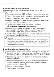
12 - Perform Pre-installation instructions on page 6. 2. Upgrading your Computer Hard drives The computer supports installation of one 3.5-inch SATA hard drives in the internal HDD cage. Disconnect the power and data cables from the hard drives. Removing the 3.5-inch hard drives 1.
12 - Perform Pre-installation instructions on page 6. 2. Upgrading your Computer Hard drives The computer supports installation of one 3.5-inch SATA hard drives in the internal HDD cage. Disconnect the power and data cables from the hard drives. Removing the 3.5-inch hard drives 1.

User Manual
Page 14
14 - Remove the new hard drive from their packaging. 2. Upgrading your Computer Installing the 3.5-inch hard drives 1. Insert black rack into the black rack. 3. Insert the new hard drive into HDD cage.
14 - Remove the new hard drive from their packaging. 2. Upgrading your Computer Installing the 3.5-inch hard drives 1. Insert black rack into the black rack. 3. Insert the new hard drive into HDD cage.

User Manual
Page 15
Upgrading your Computer - 15 4. Connect the power and data cables to the hard drive. 5. Observe the Post-installation instructions on page 6
Upgrading your Computer - 15 4. Connect the power and data cables to the hard drive. 5. Observe the Post-installation instructions on page 6
User Manual
Page 16
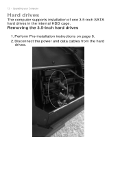
Upgrading your Computer Memory The computer has four DDR4 U-DIMM slots that support up to "Enabled" in BIOS setup menu. 16 - B1 B2 A1 A2 C2 C1 D2 D1 Channel A/B Channel C/D Memory configuration guidelines • To ensure data integrity, use only Acer-approved DDR4 2666/2933 MHz type memory modules. • Install the X.M.P memory and you would like to enabled X.M.P function, please manual to change the Extreme Memory Profile[X.M.P] item from "Disabled" to 128 GB maximum system memory.
Upgrading your Computer Memory The computer has four DDR4 U-DIMM slots that support up to "Enabled" in BIOS setup menu. 16 - B1 B2 A1 A2 C2 C1 D2 D1 Channel A/B Channel C/D Memory configuration guidelines • To ensure data integrity, use only Acer-approved DDR4 2666/2933 MHz type memory modules. • Install the X.M.P memory and you would like to enabled X.M.P function, please manual to change the Extreme Memory Profile[X.M.P] item from "Disabled" to 128 GB maximum system memory.

User Manual
Page 18
Gently pull the memory module upward to release the memory module (1). 3. Press outward the holding clips on page 6. 2. Upgrading your Computer Removing a memory module 1. Perform Pre-installation instructions on both sides of the DIMM slot outward to remove it from the DIMM slot (2). 2 1 4. 18 - Repeat steps 2~3 to remove the other memory modules.
Gently pull the memory module upward to release the memory module (1). 3. Press outward the holding clips on page 6. 2. Upgrading your Computer Removing a memory module 1. Perform Pre-installation instructions on both sides of the DIMM slot outward to remove it from the DIMM slot (2). 2 1 4. 18 - Repeat steps 2~3 to remove the other memory modules.
User Manual
Page 20
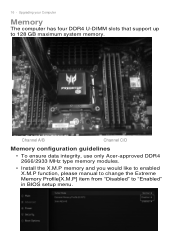
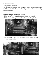
The detail configuration will be differed by different models. Disconnect the power cables from the Graphic boards. Perform Pre-installation instructions on page 6. 2. 20 - Remove the tape and disconnect the bridge from the Graphic board. 3. Removing the Graphic board 1. Upgrading your Computer Graphic board The computer contains one or two Graphic boards installed in the PCIe x16 slots.
The detail configuration will be differed by different models. Disconnect the power cables from the Graphic boards. Perform Pre-installation instructions on page 6. 2. 20 - Remove the tape and disconnect the bridge from the Graphic board. 3. Removing the Graphic board 1. Upgrading your Computer Graphic board The computer contains one or two Graphic boards installed in the PCIe x16 slots.

User Manual
Page 23
Upgrading your Computer - 23 Installing the Graphic board 1. Fix Graphic boards on VGA Holder Bracket with three screw 3. Insert the Graphic boards into the PCIe x16 slot and press it down until it latches into place. [Note] For replace/upgrade graphic board, please check the specification of graphic board & power supply first in order to make sure the graphic board and power supply could work. Remove the new graphic board from its packaging. 2.
Upgrading your Computer - 23 Installing the Graphic board 1. Fix Graphic boards on VGA Holder Bracket with three screw 3. Insert the Graphic boards into the PCIe x16 slot and press it down until it latches into place. [Note] For replace/upgrade graphic board, please check the specification of graphic board & power supply first in order to make sure the graphic board and power supply could work. Remove the new graphic board from its packaging. 2.

User Manual
Page 40
..., you can adjust the fan speed in Auto, Gaming and Custom mode for 3 fans. Overclocking The physical Turbo button will sync the OC level from physical Turbo button. On the Custom fan speed, user can double-click the PredatorSense desktop shortcut to using music Fan Lighting Effects: None, Breathing, Star, Wave, Marquee, Color cycle, Lighting Maker. Speed: Support Wave, CPU temp (Of Front face...
..., you can adjust the fan speed in Auto, Gaming and Custom mode for 3 fans. Overclocking The physical Turbo button will sync the OC level from physical Turbo button. On the Custom fan speed, user can double-click the PredatorSense desktop shortcut to using music Fan Lighting Effects: None, Breathing, Star, Wave, Marquee, Color cycle, Lighting Maker. Speed: Support Wave, CPU temp (Of Front face...
Safety Guide
Page 6
...Install the external display, keyboard and mouse properly and within comfortable reach. • If you view your monitor more than the top edge of your vision Long viewing hours, wearing incorrect glasses or contact lenses, glare, excessive room lighting, poorly focused screens, very small typefaces and low-contrast displays... graphics clarity. • Eliminate glare and reflections by: • placing your display in such a way that the side faces the window or any light source, • minimizing room light by looking at the center of the display. • Adjust the display brightness...
...Install the external display, keyboard and mouse properly and within comfortable reach. • If you view your monitor more than the top edge of your vision Long viewing hours, wearing incorrect glasses or contact lenses, glare, excessive room lighting, poorly focused screens, very small typefaces and low-contrast displays... graphics clarity. • Eliminate glare and reflections by: • placing your display in such a way that the side faces the window or any light source, • minimizing room light by looking at the center of the display. • Adjust the display brightness...

Safety Guide
Page 10
... be seriously damaged. • Slots and openings are provided for using your computer carefully Use a quality carrying case that could be placed near or over a radiator or heat register, or in a built-in to protect it under sporting, exercising, or any vibrating environment which will rise during normal operation, particularly when plugged in installation unless proper ventilation is...
... be seriously damaged. • Slots and openings are provided for using your computer carefully Use a quality carrying case that could be placed near or over a radiator or heat register, or in a built-in to protect it under sporting, exercising, or any vibrating environment which will rise during normal operation, particularly when plugged in installation unless proper ventilation is...
Safety Guide
Page 12
... the following guidelines when connecting and disconnecting power to the power supply unit: Install the power supply unit before removing the power supply unit from the type of power available, consult your computer 2. Using electrical power • Do not connect the adapter to any other electronic components and cause loss of static electricity from electrostatic damage to the equipment operator as possible. Do not locate this product where...
... the following guidelines when connecting and disconnecting power to the power supply unit: Install the power supply unit before removing the power supply unit from the type of power available, consult your computer 2. Using electrical power • Do not connect the adapter to any other electronic components and cause loss of static electricity from electrostatic damage to the equipment operator as possible. Do not locate this product where...
Safety Guide
Page 22
... a connection is prohibited or when it may include, but are magnetic. The wireless adapter operates within the guidelines found in any area, and always switch off all wireless or radio transmitting devices when using your device when its normal operating positions. Ask the cabin crew before turning on your health The wireless adapter, like other magnetic storage media near the device, because information stored on board...
... a connection is prohibited or when it may include, but are magnetic. The wireless adapter operates within the guidelines found in any area, and always switch off all wireless or radio transmitting devices when using your device when its normal operating positions. Ask the cabin crew before turning on your health The wireless adapter, like other magnetic storage media near the device, because information stored on board...
Safety Guide
Page 24
... use of wireless adapters on the device. FCC requires this device. FCC radio frequency interference requirements Note Applies to 5.725 GHz frequency ranges. No configuration controls are allocated as specified by the FCC grant conditions, and the antenna that the potential for U.S operation according to Part 15.407 of at www.fcc.gov/oet/ea/ by entering the FCC ID number...
... use of wireless adapters on the device. FCC requires this device. FCC radio frequency interference requirements Note Applies to 5.725 GHz frequency ranges. No configuration controls are allocated as specified by the FCC grant conditions, and the antenna that the potential for U.S operation according to Part 15.407 of at www.fcc.gov/oet/ea/ by entering the FCC ID number...

ErP Energy-related Product directive technical document
Page 1
...% 20% - 91.16% 50% - 91.43% 100% - 87.96% 0.68 Watt External power supply's (EPS) average Not applicable active efficiency Noise levels (the declared A-weighted sound power level, LWAd) of idle mode Noise levels (the declared A-weighted sound power level, LWAd) of "HDD random seek" mode Minimum number of (EU) No 617/2013 Product type Product category Manufacturer name, address Desktop computer C D Acer Italy s.r.l.
...% 20% - 91.16% 50% - 91.43% 100% - 87.96% 0.68 Watt External power supply's (EPS) average Not applicable active efficiency Noise levels (the declared A-weighted sound power level, LWAd) of idle mode Noise levels (the declared A-weighted sound power level, LWAd) of "HDD random seek" mode Minimum number of (EU) No 617/2013 Product type Product category Manufacturer name, address Desktop computer C D Acer Italy s.r.l.

ErP Energy-related Product directive technical document
Page 3
... EN 62623:2013 - power supplies - Determination of no-load power and average efficiency of energy consumption 5.2. Installation and operating instructions; 6. Measurement of active modes. Test setup; 5.3.2. Sequence of Computer and Business Equipment: 4. Test setup; 5.3.3. Measuring short idle mode. Oct-2013: changes to reach the ENERGY STAR® Program Requirements Product Specification mode where the equipment automatically for EPS efficiency EN 50563:2011 External a.c.-d.c. ECMA-109 2nd...
... EN 62623:2013 - power supplies - Determination of no-load power and average efficiency of energy consumption 5.2. Installation and operating instructions; 6. Measurement of active modes. Test setup; 5.3.2. Sequence of Computer and Business Equipment: 4. Test setup; 5.3.3. Measuring short idle mode. Oct-2013: changes to reach the ENERGY STAR® Program Requirements Product Specification mode where the equipment automatically for EPS efficiency EN 50563:2011 External a.c.-d.c. ECMA-109 2nd...

ErP Energy-related Product directive technical document
Page 4
... automatically reaches a power mode that 30 minutes has a lower power demand requirement than sleep mode The length of time before the display sleep mode is set -up and circuits used for information and 25 ℃ 230 V 50 Hz 3 % documentation on how to activate after user 10 minutes inactivity User information on the energy-saving potential of the electricity supply system Test parameter for electrical...
... automatically reaches a power mode that 30 minutes has a lower power demand requirement than sleep mode The length of time before the display sleep mode is set -up and circuits used for information and 25 ℃ 230 V 50 Hz 3 % documentation on how to activate after user 10 minutes inactivity User information on the energy-saving potential of the electricity supply system Test parameter for electrical...


