
Service Guide
Page 7
... 9 Indicators 10 Easy-Launch Buttons 10 Touchpad Basics (with fingerprint reader 11 Using the Keyboard 12 Lock Keys and embedded numeric keypad 12 Windows Keys 13 Hot Keys 14 Special Key 15 Using the System Utilities 16 Acer GridVista (dual-display compatible 16 Hardware Specifications and Configurations 18 System Utilities 25 BIOS Setup Utility 25 Navigating the BIOS Utility 25 Information 26 Main 27 Advanced 28 Security 30 Power 33 Boot 35 Exit 36 BIOS Flash Utility 37 Remove HDD/BIOS Utility 39 Machine Disassembly and Replacement...
... 9 Indicators 10 Easy-Launch Buttons 10 Touchpad Basics (with fingerprint reader 11 Using the Keyboard 12 Lock Keys and embedded numeric keypad 12 Windows Keys 13 Hot Keys 14 Special Key 15 Using the System Utilities 16 Acer GridVista (dual-display compatible 16 Hardware Specifications and Configurations 18 System Utilities 25 BIOS Setup Utility 25 Navigating the BIOS Utility 25 Information 26 Main 27 Advanced 28 Security 30 Power 33 Boot 35 Exit 36 BIOS Flash Utility 37 Remove HDD/BIOS Utility 39 Machine Disassembly and Replacement...

Service Guide
Page 8
... Port 103 Replacing the Mainboard 105 Replacing the Modem Module 106 Replacing the Bluetooth Board 107 Replacing the Right Speaker Module 107 Replacing the Launch Board 109 Replacing the Finger Print Reader 110 Replacing the Touch Pad Bracket 110 Replacing the Left Speaker Module 111 Replacing the Upper Cover 111 Replacing the LCD Module 113 Replacing the Antenna Cables 115 Replacing the Keyboard 117 Replacing the Switch Cover 117 Replacing the WLAN Module 119 Replacing the Hard Disk Drive Module 119 Replacing the DIMM Modules 120 Replacing the ODD Module 121 Replacing...
... Port 103 Replacing the Mainboard 105 Replacing the Modem Module 106 Replacing the Bluetooth Board 107 Replacing the Right Speaker Module 107 Replacing the Launch Board 109 Replacing the Finger Print Reader 110 Replacing the Touch Pad Bracket 110 Replacing the Left Speaker Module 111 Replacing the Upper Cover 111 Replacing the LCD Module 113 Replacing the Antenna Cables 115 Replacing the Keyboard 117 Replacing the Switch Cover 117 Replacing the WLAN Module 119 Replacing the Hard Disk Drive Module 119 Replacing the DIMM Modules 120 Replacing the ODD Module 121 Replacing...

Service Guide
Page 9
... Intermittent Problems 141 Undetermined Problems 141 POST Codes Tables 142 Port 80 POST Codes 142 POST Keys and Messages 144 Jumper and Connector Locations 145 Top View 145 Bottom View 146 Clearing Password Check and BIOS Recovery 147 Clearing Password Check 147 BIOS Recovery by Crisis Disk 148 FRU (Field Replaceable Unit) List 149 TravelMate 4730/4730G Exploded Diagrams 150 Main Module 150 LCD Module 151 TravelMate 4730/4730G FRU List 152 Model Definition and Configuration 166 TravelMate 4730/4730G Series 166...
... Intermittent Problems 141 Undetermined Problems 141 POST Codes Tables 142 Port 80 POST Codes 142 POST Keys and Messages 144 Jumper and Connector Locations 145 Top View 145 Bottom View 146 Clearing Password Check and BIOS Recovery 147 Clearing Password Check 147 BIOS Recovery by Crisis Disk 148 FRU (Field Replaceable Unit) List 149 TravelMate 4730/4730G Exploded Diagrams 150 Main Module 150 LCD Module 151 TravelMate 4730/4730G FRU List 152 Model Definition and Configuration 166 TravelMate 4730/4730G Series 166...

Service Guide
Page 16
... keys give users one-touch access to protection and manageability features for certain models). Enables/disables the wireless function. Locks and releases the lid. 6 Chapter 1 Headphones/ speaker/line-out jack Bluetooth communication switch Wireless communication switch Latch Connects to work. No. 9 Icon 10 11 12 13 Closed Front View Item Click buttons (left, center* and right) Touchpad Power button Description The left and right mouse buttons. *The center button serves as Acer BioProtection fingerprint reader supporting Acer FingerNav 4-way control function...
... keys give users one-touch access to protection and manageability features for certain models). Enables/disables the wireless function. Locks and releases the lid. 6 Chapter 1 Headphones/ speaker/line-out jack Bluetooth communication switch Wireless communication switch Latch Connects to work. No. 9 Icon 10 11 12 13 Closed Front View Item Click buttons (left, center* and right) Touchpad Power button Description The left and right mouse buttons. *The center button serves as Acer BioProtection fingerprint reader supporting Acer FingerNav 4-way control function...

Service Guide
Page 17
... network. Note: Push to a television or display device with HDMI input (only for certain models). PC Card slot eject button Ejects the PC Card from the slot. Connects to remove/install the card. Only one Type II PC Card. Chapter 1 7 Accepts Secure Digital (SD), MultiMediaCard (MMC), Memory Stick (MS), Memory Stick PRO (MS PRO), xD-Picture Card (xD). USB mouse, USB camera). Left View No. 1 2 3 4 5 6 7 8 Icon HDMI Item Acer EasyPort IV connector Ethernet (RJ-45) port External display (VGA) port HDMI 2 USB 2.0 ports 5-in-1 card reader...
... network. Note: Push to a television or display device with HDMI input (only for certain models). PC Card slot eject button Ejects the PC Card from the slot. Connects to remove/install the card. Only one Type II PC Card. Chapter 1 7 Accepts Secure Digital (SD), MultiMediaCard (MMC), Memory Stick (MS), Memory Stick PRO (MS PRO), xD-Picture Card (xD). USB mouse, USB camera). Left View No. 1 2 3 4 5 6 7 8 Icon HDMI Item Acer EasyPort IV connector Ethernet (RJ-45) port External display (VGA) port HDMI 2 USB 2.0 ports 5-in-1 card reader...

Service Guide
Page 20
.... Lights up when Caps Lock is activated. To set to -read status indicators: The front panel indicators are visible even when the computer cover is activated. Enables/disables the wireless function. 10 Chapter 1 They are called easy-launch buttons. Easy-Launch Buttons Located beside the keyboard are application buttons. Icon Function Bluetooth Description Indicates the status of wireless LAN communication. Indicators The computer has several easy-to email and Internet programs, but can be reset by users. Lights...
.... Lights up when Caps Lock is activated. To set to -read status indicators: The front panel indicators are visible even when the computer cover is activated. Enables/disables the wireless function. 10 Chapter 1 They are called easy-launch buttons. Easy-Launch Buttons Located beside the keyboard are application buttons. Icon Function Bluetooth Description Indicates the status of wireless LAN communication. Indicators The computer has several easy-to email and Internet programs, but can be reset by users. Lights...
Service Guide
Page 35
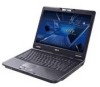
... F12 Boot Menu is already properly configured and optimized, and you may need to run Setup. Read this utility. Navigation keys for parameters are six menu options: Information, Main, Advanced, Security, Boot, and Exit. However, if you encounter configuration problems, you do not need to run this carefully when making changes to "enabled". You can change boot device without entering BIOS Setup Utility, please set to "disabled". To activate the BIOS Utility, press F2 during POST to enter multi-boot menu...
... F12 Boot Menu is already properly configured and optimized, and you may need to run Setup. Read this utility. Navigation keys for parameters are six menu options: Information, Main, Advanced, Security, Boot, and Exit. However, if you encounter configuration problems, you do not need to run this carefully when making changes to "enabled". You can change boot device without entering BIOS Setup Utility, please set to "disabled". To activate the BIOS Utility, press F2 during POST to enter multi-boot menu...

Service Guide
Page 36
...) is subject to different models. InsydeH20 Setup Utility Information Main Advanced Security Power Boot Exit Rev. 3.5 CPU Type: CPU Speed: Intel (R) Core (TM)2 Duo CPU 2.53GHz T9400 @ 2.53GHz HDD Model Name: HDD Serial Number: ATAPI Model Name: ST9250827AS 5RG01NK8 Slimtype DVD A DS8A2S System BIOS Version: VGA BIOS Version: Serial Number: Asset Tag Number: Product Name: Manufacturer Name: UUID: v0.16-T6 nVidia NB9M-GS VER62.98.1F.00.00 TravelMate 4730 Acer DCEB0597-DE29-11D3-444C...
...) is subject to different models. InsydeH20 Setup Utility Information Main Advanced Security Power Boot Exit Rev. 3.5 CPU Type: CPU Speed: Intel (R) Core (TM)2 Duo CPU 2.53GHz T9400 @ 2.53GHz HDD Model Name: HDD Serial Number: ATAPI Model Name: ST9250827AS 5RG01NK8 Slimtype DVD A DS8A2S System BIOS Version: VGA BIOS Version: Serial Number: Asset Tag Number: Product Name: Manufacturer Name: UUID: v0.16-T6 nVidia NB9M-GS VER62.98.1F.00.00 TravelMate 4730 Acer DCEB0597-DE29-11D3-444C...
Service Guide
Page 40
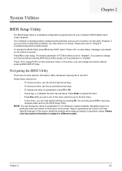
...;→ Select Menu F5/F6 Change Values F9 Setup Default Enter SelectXSubMenu F10 Save and Exit The table below describes the parameters in this password protects the BIOS Setup Utility from unauthorized access. Parameter Supervisor Password Is User Password Is HDD Password Is Set Supervisor Password Set User Password Set HDD Password Power on password [Enabled] Rev. 3.5 Exit Item Specific Help Install or Change the password and the length of the hard disk password. The user can not either enter the Setup menu nor change the value of...
...;→ Select Menu F5/F6 Change Values F9 Setup Default Enter SelectXSubMenu F10 Save and Exit The table below describes the parameters in this password protects the BIOS Setup Utility from unauthorized access. Parameter Supervisor Password Is User Password Is HDD Password Is Set Supervisor Password Set User Password Set HDD Password Power on password [Enabled] Rev. 3.5 Exit Item Specific Help Install or Change the password and the length of the hard disk password. The user can not either enter the Setup menu nor change the value of...
Service Guide
Page 41
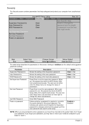
... set the user or the supervisor password: 1. Removing a Password Follow these steps as you can not exceeds 8 alphanumeric characters (A-Z, a-z, 0-9, not case sensitive). Type a password in the "Confirm New Password" field. Press Enter. Chapter 2 31 IMPORTANT:Be very careful when typing your password because the characters do not appear on boot parameter. 5. When you are done, press F10 to save the changes and exit the BIOS Setup Utility...
... set the user or the supervisor password: 1. Removing a Password Follow these steps as you can not exceeds 8 alphanumeric characters (A-Z, a-z, 0-9, not case sensitive). Type a password in the "Confirm New Password" field. Press Enter. Chapter 2 31 IMPORTANT:Be very careful when typing your password because the characters do not appear on boot parameter. 5. When you are done, press F10 to save the changes and exit the BIOS Setup Utility...

Service Guide
Page 42
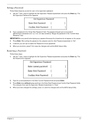
... changes and exit the BIOS Setup Utility. Retype the password in the Enter Current Password field and press Enter. 3. When you the Setup Warning. Type a password in the Enter New Password field. If the verification is complete after the user presses Enter. If the new password and confirm new password strings do not match, the screen will display as following message. 32 Chapter 2 If desired, you can enable the Password on boot parameter. 6. After setting the password...
... changes and exit the BIOS Setup Utility. Retype the password in the Enter Current Password field and press Enter. 3. When you the Setup Warning. Type a password in the Enter New Password field. If the verification is complete after the user presses Enter. If the new password and confirm new password strings do not match, the screen will display as following message. 32 Chapter 2 If desired, you can enable the Password on boot parameter. 6. After setting the password...
Service Guide
Page 47
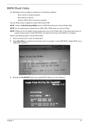
... or options • Restore a BIOS when it becomes corrupted. Select Boot Menu to modify the boot priority order, for the following steps to use the Phlash. NOTE: Do not install memory-related drivers (XMS, EMS, DPMI) when you run the Phlash utility. Press F2 during boot to Memory). Chapter 2 37 If the battery pack does not contain enough power to finish BIOS flash, the system will not boot as USB HDD...
... or options • Restore a BIOS when it becomes corrupted. Select Boot Menu to modify the boot priority order, for the following steps to use the Phlash. NOTE: Do not install memory-related drivers (XMS, EMS, DPMI) when you run the Phlash utility. Press F2 during boot to Memory). Chapter 2 37 If the battery pack does not contain enough power to finish BIOS flash, the system will not boot as USB HDD...

Service Guide
Page 133
... No Display Issue Page 125 LCD Failure Page 127 Internal Keyboard Failure Page 127 Touchpad Failure Page 128 Internal Speaker Failure Page 128 Internal Microphone Failure Page 130 ODD Failure Page 132 Rightside USB Failure Page 135 Modem Failure Page 135 WLAN/WiMAX Failure Page 136 Bluetooth Failure Page 136 Robson Module Failure Page 137 Acer EasyLaunch Button Failure Page 137 Fingerprint Reader Failure...
... No Display Issue Page 125 LCD Failure Page 127 Internal Keyboard Failure Page 127 Touchpad Failure Page 128 Internal Speaker Failure Page 128 Internal Microphone Failure Page 130 ODD Failure Page 132 Rightside USB Failure Page 135 Modem Failure Page 135 WLAN/WiMAX Failure Page 136 Bluetooth Failure Page 136 Robson Module Failure Page 137 Acer EasyLaunch Button Failure Page 137 Fingerprint Reader Failure...

Service Guide
Page 135
... reboot the computer. 4. If the computer boots correctly, add the devices one by one at a time to correct the problem. 1. Remove the drives (see "Power On Issue" on page 44). 8. Make sure that the internal display is discovered. 6. Drain any memory cards and CD/DVD discs. Reseat the memory modules. 7. Remove any stored power by removing the power cable and battery and holding down the power button for specific model procedures. 2. No Display Issue If the Display doesn't work...
... reboot the computer. 4. If the computer boots correctly, add the devices one by one at a time to correct the problem. 1. Remove the drives (see "Power On Issue" on page 44). 8. Make sure that the internal display is discovered. 6. Drain any memory cards and CD/DVD discs. Reseat the memory modules. 7. Remove any stored power by removing the power cable and battery and holding down the power button for specific model procedures. 2. No Display Issue If the Display doesn't work...
Service Guide
Page 136
See "Disassembly Process" on adjusting settings. If the display is too dim at a time to correct the problem. 1. Minimize or close all Windows. e. Remove and reinstall the video driver. 8. If the Issue is experiencing HDD or ODD BIOS information loss, disconnect and reconnect the power and data cables between devices. Replace the Motherboard. 6. Adjust the brightness to the desired resolution. c. Click Apply and check the display. If the computer is...
See "Disassembly Process" on adjusting settings. If the display is too dim at a time to correct the problem. 1. Minimize or close all Windows. e. Remove and reinstall the video driver. 8. If the Issue is experiencing HDD or ODD BIOS information loss, disconnect and reconnect the power and data cables between devices. Replace the Motherboard. 6. Adjust the brightness to the desired resolution. c. Click Apply and check the display. If the computer is...

Service Guide
Page 141
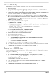
... System Recovery Options screen displays. g. Run the Windows Memory Diagnostic Tool. Ensure all external devices. 2. Run the Windows Disk Defragmenter. Restore system and file settings from a command prompt. Run a complete virus scan using System Restore. Run the Windows Vista Startup Repair Utility: a. c. Click Next. Select Startup Repair. i. Check the BIOS settings are set as the first boot device on page 44. Run Windows Check Disk by entering chkdsk /r from a known good date using up-to-date software to the operating system DVD. If...
... System Recovery Options screen displays. g. Run the Windows Memory Diagnostic Tool. Ensure all external devices. 2. Run the Windows Disk Defragmenter. Restore system and file settings from a command prompt. Run a complete virus scan using System Restore. Run the Windows Vista Startup Repair Utility: a. c. Click Next. Select Startup Repair. i. Check the BIOS settings are set as the first boot device on page 44. Run Windows Check Disk by entering chkdsk /r from a known good date using up-to-date software to the operating system DVD. If...

Service Guide
Page 150
... CRT Switch, Dock, LAN Port, external MIC or Speakers, PCI Express Card, 5-in-1 Card Reader or Volume Wheel fail, perform the following actions one at a time to determine that: • The device is ok. 3. Check the Device Manager to correct the problem. 1. If the Issue is still not resolved, see Windows Help and Support. 10. If the mouse uses a USB connection, try an alternate USB port. 4. Reinstall the program experiencing mouse...
... CRT Switch, Dock, LAN Port, external MIC or Speakers, PCI Express Card, 5-in-1 Card Reader or Volume Wheel fail, perform the following actions one at a time to determine that: • The device is ok. 3. Check the Device Manager to correct the problem. 1. If the Issue is still not resolved, see Windows Help and Support. 10. If the mouse uses a USB connection, try an alternate USB port. 4. Reinstall the program experiencing mouse...
Service Guide
Page 151
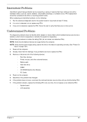
... loop mode at a time. If any error is inoperative. Power-off the computer. 2. If the problem remains, replace the following FRU one at the time of the following : 1. Follow these procedures to isolate the failing FRU (do the following devices: • Non-Acer devices • Printer, mouse, and other external devices • Battery pack • Hard disk drive • DIMM • CD-ROM/Diskette drive Module • PC Cards...
... loop mode at a time. If any error is inoperative. Power-off the computer. 2. If the problem remains, replace the following FRU one at the time of the following : 1. Follow these procedures to isolate the failing FRU (do the following devices: • Non-Acer devices • Printer, mouse, and other external devices • Battery pack • Hard disk drive • DIMM • CD-ROM/Diskette drive Module • PC Cards...

Service Guide
Page 157
... key to enter BIOS Setup menu. • If there is no Password request, BIOS Password is necessary to bypass the password check, users need to short the HW Gap to clear the password by the following steps: • Power Off a system, and remove HDD, AC and Battery from the HW Gap. • Restart system. Clearing Password Check Hardware Open Gap Description R376 Item Description Clear CMOS Jumper Location Memory bay Steps for Clearing BIOS Password Check If users set BIOS Password (Supervisor Password...
... key to enter BIOS Setup menu. • If there is no Password request, BIOS Password is necessary to bypass the password check, users need to short the HW Gap to clear the password by the following steps: • Power Off a system, and remove HDD, AC and Battery from the HW Gap. • Restart system. Clearing Password Check Hardware Open Gap Description R376 Item Description Clear CMOS Jumper Location Memory bay Steps for Clearing BIOS Password Check If users set BIOS Password (Supervisor Password...

Service Guide
Page 192
... LCD Failure 127 LCD Module Disassembly Flowchart 88 LCD Panel 93 lower cover 49 M Main Unit Disassembly Flowchart 58 Mainboard 79 media access on indicator 10 MediaTouch Button Failure 138 Memory Check 124 Model Definition 166 Modem Failure 135 Modem Module 78 N No Display Issue 125 Notebook Manager hotkey 14 num lock on indicator 10 O ODD Failure 132 Online Support Information 179 optical drive module 56 P Panel 5 Bottom 9 left 5 PC Card 10 Port 80 POST Codes 142 POST Codes Port...
... LCD Failure 127 LCD Module Disassembly Flowchart 88 LCD Panel 93 lower cover 49 M Main Unit Disassembly Flowchart 58 Mainboard 79 media access on indicator 10 MediaTouch Button Failure 138 Memory Check 124 Model Definition 166 Modem Failure 135 Modem Module 78 N No Display Issue 125 Notebook Manager hotkey 14 num lock on indicator 10 O ODD Failure 132 Online Support Information 179 optical drive module 56 P Panel 5 Bottom 9 left 5 PC Card 10 Port 80 POST Codes 142 POST Codes Port...


