Service Guide
Page 7
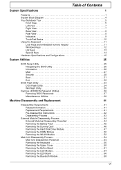
... Related Information 41 Replacement Requirements 41 Pre-disassembly Instructions 42 Disassembly Process 43 External Module Disassembly Process 44 External Modules Disassembly Flowchart 44 Removing the Battery Pack 45 Removing the Dummy Card 46 Removing the Hard Disk Drive Module 47 Removing the DIMM Module 50 Removing the WLAN Module 52 Main...
... Related Information 41 Replacement Requirements 41 Pre-disassembly Instructions 42 Disassembly Process 43 External Module Disassembly Process 44 External Modules Disassembly Flowchart 44 Removing the Battery Pack 45 Removing the Dummy Card 46 Removing the Hard Disk Drive Module 47 Removing the DIMM Module 50 Removing the WLAN Module 52 Main...
Service Guide
Page 8
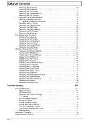
...95 Replacing the Camera Board 97 Replacing the LCD Bezel 98 Main Unit Reassembly Process 101 Replacing the Speaker Modules 101 Replacing the RTC Battery 103 Replacing the Thermal Module 104 Replacing the CRT Board 105 Replacing the Main Board 106 Replacing the I/O Card 108 Replacing the Bluetooth... Replacing the Keyboard 121 Replacing the Wireless LAN Module 122 Replacing the DIMM Module 124 Replacing the Hard Disk Drive 126 Replacing the Battery 128 Replace the Dummy Card 129 Troubleshooting 131 Common Problems 131 Power On Issue 132 No Display Issue 133 Random Loss of BIOS...
...95 Replacing the Camera Board 97 Replacing the LCD Bezel 98 Main Unit Reassembly Process 101 Replacing the Speaker Modules 101 Replacing the RTC Battery 103 Replacing the Thermal Module 104 Replacing the CRT Board 105 Replacing the Main Board 106 Replacing the I/O Card 108 Replacing the Bluetooth... Replacing the Keyboard 121 Replacing the Wireless LAN Module 122 Replacing the DIMM Module 124 Replacing the Hard Disk Drive 126 Replacing the Battery 128 Replace the Dummy Card 129 Troubleshooting 131 Common Problems 131 Power On Issue 132 No Display Issue 133 Random Loss of BIOS...
Service Guide
Page 12
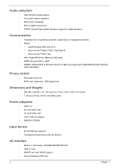
...Dimensions and Weight) • 285 (W) x 204 (D) x 22.1/30 (H) mm (11.22 x 8.03 x 0.87/1.18 inches) • 1.35 kg (2.97 lbs.) with 6-cell battery pack Power subsystem • ACPI 3.0 • 62.16 W 5600 mAh • 47.52 W 4400 mAh • 3-pin 30 W AC adapter • ENERGY STAR® Input... two buttons I/O interface • Multi-in digital microphone • S/PDIF (Sony/Philips Digital Interface) support for digital speakers Communication • Integrated Acer Crystal Eye webcam, supporting 0.3-megapixel resolution • WLAN: • Intel® Wireless WiFi Link 5100 •...
...Dimensions and Weight) • 285 (W) x 204 (D) x 22.1/30 (H) mm (11.22 x 8.03 x 0.87/1.18 inches) • 1.35 kg (2.97 lbs.) with 6-cell battery pack Power subsystem • ACPI 3.0 • 62.16 W 5600 mAh • 47.52 W 4400 mAh • 3-pin 30 W AC adapter • ENERGY STAR® Input... two buttons I/O interface • Multi-in digital microphone • S/PDIF (Sony/Philips Digital Interface) support for digital speakers Communication • Integrated Acer Crystal Eye webcam, supporting 0.3-megapixel resolution • WLAN: • Intel® Wireless WiFi Link 5100 •...
Service Guide
Page 16
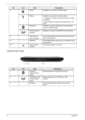
The left and right buttons function like the left , and right) Palmrest Power button/ indicator Indicates the computer's battery status. 1. Enables/disables the 3G/Wireless LAN function. Turns the computer on and off. Left and right speakers deliver stereo audio output. 6 Chapter 1...: The light shows amber when the light is charging. 2. No. 7 Icon Item Power Description Indicates the computer's power status. 8 9 10 Closed Front View Battery Bluetooth Communication indicator Click buttons (left and right mouse buttons. Fully charged: the light shows blue when in AC mode.
The left and right buttons function like the left , and right) Palmrest Power button/ indicator Indicates the computer's battery status. 1. Enables/disables the 3G/Wireless LAN function. Turns the computer on and off. Left and right speakers deliver stereo audio output. 6 Chapter 1...: The light shows amber when the light is charging. 2. No. 7 Icon Item Power Description Indicates the computer's power status. 8 9 10 Closed Front View Battery Bluetooth Communication indicator Click buttons (left and right mouse buttons. Fully charged: the light shows blue when in AC mode.
Service Guide
Page 18
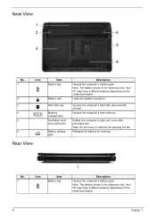
... computer's hard disk (secured with screws) Houses the computer's main memory. No. 1 Icon Item Battery bay Description Houses the computer's battery pack. Releases the battery for reference only. Note: The battery shown is for removal. Base View No. 1 Icon 2 3 4 5 6 Rear View Item Battery bay Battery lock Hard disk bay Memory compartment Ventilation slots and cooling fan...
... computer's hard disk (secured with screws) Houses the computer's main memory. No. 1 Icon Item Battery bay Description Houses the computer's battery pack. Releases the battery for reference only. Note: The battery shown is for removal. Base View No. 1 Icon 2 3 4 5 6 Rear View Item Battery bay Battery lock Hard disk bay Memory compartment Ventilation slots and cooling fan...
Service Guide
Page 19
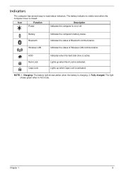
.... HDD Num Lock Caps Lock Indicates when the hard disk drive is charging. 2. Charging: The battery light shows amber when the battery is active. Icon Function Power Description Indicates the computer is activated. Indicates the status of Wireless LAN communication. NOTE: 1. Indicators The computer has several easy-...
.... HDD Num Lock Caps Lock Indicates when the hard disk drive is charging. 2. Charging: The battery light shows amber when the battery is active. Icon Function Power Description Indicates the computer is activated. Indicates the status of Wireless LAN communication. NOTE: 1. Indicators The computer has several easy-...

Service Guide
Page 32
... active channels • 12---13 channels for passive channels 11Mbps with fall back rates of 5.5, 2, and 1Mbps CSMA/CA with ACK 18dBm typically Battery Item Vendor & model name Battery Type Specification 6 Cell SANYO UM-2009E Li-Ion 3S2P PANASONIC UM-2009E Li-Ion 3S2P SIMPLO UM-2009E Li-Ion 3S2P SIMPLO UM...
... active channels • 12---13 channels for passive channels 11Mbps with fall back rates of 5.5, 2, and 1Mbps CSMA/CA with ACK 18dBm typically Battery Item Vendor & model name Battery Type Specification 6 Cell SANYO UM-2009E Li-Ion 3S2P PANASONIC UM-2009E Li-Ion 3S2P SIMPLO UM-2009E Li-Ion 3S2P SIMPLO UM...

Service Guide
Page 33
Item Pack capacity Number of battery cell Package configuration Specification 6 Cell SANYO 6 cell 4400mAh SANYO 6 cell 5600mAh PANASONIC 6 cell 4400mAh PANASONIC 6 cell 5800mAh SAMSUNG 6 cell 4400mAh SAMSUNG 6 cell 5600mAh LGC 6 cell 5600mAh 6 3 cells in series, 2 series in parallel Chapter 1 23
Item Pack capacity Number of battery cell Package configuration Specification 6 Cell SANYO 6 cell 4400mAh SANYO 6 cell 5600mAh PANASONIC 6 cell 4400mAh PANASONIC 6 cell 5800mAh SAMSUNG 6 cell 4400mAh SAMSUNG 6 cell 5600mAh LGC 6 cell 5600mAh 6 3 cells in series, 2 series in parallel Chapter 1 23
Service Guide
Page 54
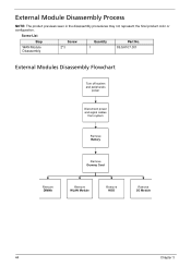
WAN Module 2*3 1 Disassembly 86.SA107.001 External Modules Disassembly Flowchart Turn off system and peripherals power Disconnect power and signal cables from system Remove Battery Remove Dummy Card Remove DIMMs Remove WLAN Module Remove HDD Remove 3G Module 44 Chapter 3 Screw List Step Screw Quantity Part No. External Module Disassembly Process NOTE: The product previews seen in the disassembly procedures may not represent the final product color or configuration.
WAN Module 2*3 1 Disassembly 86.SA107.001 External Modules Disassembly Flowchart Turn off system and peripherals power Disconnect power and signal cables from system Remove Battery Remove Dummy Card Remove DIMMs Remove WLAN Module Remove HDD Remove 3G Module 44 Chapter 3 Screw List Step Screw Quantity Part No. External Module Disassembly Process NOTE: The product previews seen in the disassembly procedures may not represent the final product color or configuration.

Service Guide
Page 55
Slide and hold the battery release latch to the unlock position. 3. Turn the computer over. 2. Removing the Battery Pack 1. Slide the battery lock/unlock latch to the release position (1), then slide out the battery pack from the main unit (2). 2 1 Chapter 3 45
Slide and hold the battery release latch to the unlock position. 3. Turn the computer over. 2. Removing the Battery Pack 1. Slide the battery lock/unlock latch to the release position (1), then slide out the battery pack from the main unit (2). 2 1 Chapter 3 45
Service Guide
Page 57
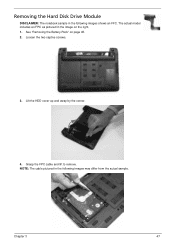
Grasp the FPC cable and lift to remove. Loosen the two captive screws. 3. Lift the HDD cover up and away by the corner. 4. Chapter 3 47 NOTE: The cable pictured in the following images shows an FFC. The actual model includes an FPC as pictured in the image on page 45. 2. See "Removing the Battery Pack" on the right. 1. Removing the Hard Disk Drive Module DISCLAIMER: The notebook sample in the following images may differ from the actual sample.
Grasp the FPC cable and lift to remove. Loosen the two captive screws. 3. Lift the HDD cover up and away by the corner. 4. Chapter 3 47 NOTE: The cable pictured in the following images shows an FFC. The actual model includes an FPC as pictured in the image on page 45. 2. See "Removing the Battery Pack" on the right. 1. Removing the Hard Disk Drive Module DISCLAIMER: The notebook sample in the following images may differ from the actual sample.

Service Guide
Page 60
See "Removing the Battery Pack" on page 45. 2. Push outwards the memory module clips. 50 Chapter 3 Lift the memory cover away. 4. Removing the DIMM Module 1. Loosen the four captive screws in the memory cover. 3.
See "Removing the Battery Pack" on page 45. 2. Push outwards the memory module clips. 50 Chapter 3 Lift the memory cover away. 4. Removing the DIMM Module 1. Loosen the four captive screws in the memory cover. 3.

Service Guide
Page 62
Loosen the four captive screws in the memory cover. 3. IMPORTANT:Take note of the Main (1. black) and Auxiliary (2. Detach the two cables from the Wireless LAN module. See "Removing the Battery Pack" on page 45.. 2. white) connectors. 52 Chapter 3 Removing the WLAN Module 1. Lift and remove the memory cover. 4.
Loosen the four captive screws in the memory cover. 3. IMPORTANT:Take note of the Main (1. black) and Auxiliary (2. Detach the two cables from the Wireless LAN module. See "Removing the Battery Pack" on page 45.. 2. white) connectors. 52 Chapter 3 Removing the WLAN Module 1. Lift and remove the memory cover. 4.

Service Guide
Page 64
... ove Upper Cover Rem ove Left Speaker Module Rem ove Right Speaker Module Rem ove TouchPad Bracket Lower Cover Rem ove Mainboard Rem ove RTC Battery Rem ove Thermal Module Rem ove CPU 54 Chapter 3 NOTE: The product previews seen in the same position. Main Unit Disassembly Process IMPORTANT: Cable paths...
... ove Upper Cover Rem ove Left Speaker Module Rem ove Right Speaker Module Rem ove TouchPad Bracket Lower Cover Rem ove Mainboard Rem ove RTC Battery Rem ove Thermal Module Rem ove CPU 54 Chapter 3 NOTE: The product previews seen in the same position. Main Unit Disassembly Process IMPORTANT: Cable paths...
Service Guide
Page 66
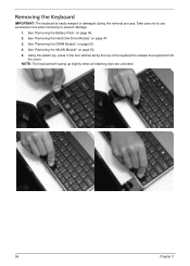
... Disk Drive Module" on page 52. 5. See "Removing the WLAN Module" on page 47. 3. See "Removing the DIMM Module" on page 45. 2. See "Removing the Battery Pack" on page 50. 4. Using the plastic pry, press in the four latches along the top of the keyboard to prevent damage. 1. NOTE: The keyboard...
... Disk Drive Module" on page 52. 5. See "Removing the WLAN Module" on page 47. 3. See "Removing the DIMM Module" on page 45. 2. See "Removing the Battery Pack" on page 50. 4. Using the plastic pry, press in the four latches along the top of the keyboard to prevent damage. 1. NOTE: The keyboard...

Service Guide
Page 85
See "Removing the Mainboard" on page 71. 2. Pry the RTC battery out of all batteries. 1. Chapter 3 75 Removing the RTC Battery IMPORTANT:Observe local regulations in the disposal of the holding clips.
See "Removing the Mainboard" on page 71. 2. Pry the RTC battery out of all batteries. 1. Chapter 3 75 Removing the RTC Battery IMPORTANT:Observe local regulations in the disposal of the holding clips.

Service Guide
Page 113
Chapter 3 103 Replacing the RTC Battery 1. Place the RTC battery into the holding clips on the main board.
Chapter 3 103 Replacing the RTC Battery 1. Place the RTC battery into the holding clips on the main board.

Service Guide
Page 138
Close the locking latch. 128 Chapter 3 Replacing the Battery 1. Slide the battery into position. 2.
Close the locking latch. 128 Chapter 3 Replacing the Battery 1. Slide the battery into position. 2.
Service Guide
Page 142
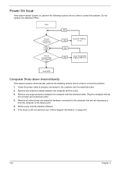
... and the electrical outlet. Check the power cable is still not resolved, see "Online Support Information" on OK Check Daughter/B & FFC Whether OK Swap AC /Battery NG to try OK Swap Daughter/B NG Re-plug PWR FFC Swap M/B Computer Shuts down Intermittently If the system powers off at intervals, perform the... to the computer that are not necessary to boot the computer to correct the problem. Do not replace non-defective FRUs: SSttaarrtt OK Check AC/Battery Power on page 241. 132 Chapter 4 Remove any surge protectors between the computer and the outlet. 3.
... and the electrical outlet. Check the power cable is still not resolved, see "Online Support Information" on OK Check Daughter/B & FFC Whether OK Swap AC /Battery NG to try OK Swap Daughter/B NG Re-plug PWR FFC Swap M/B Computer Shuts down Intermittently If the system powers off at intervals, perform the... to the computer that are not necessary to boot the computer to correct the problem. Do not replace non-defective FRUs: SSttaarrtt OK Check AC/Battery Power on page 241. 132 Chapter 4 Remove any surge protectors between the computer and the outlet. 3.
Service Guide
Page 143
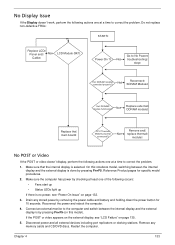
... and Module properly No replace thermal connected? No Reconnect SDRAM Module Ext. Make sure that the internal display is by removing the power cable and battery and holding down the power button for specific model procedures. 2. Make sure the computer has power by pressing Fn+F5. Chapter 4 133 On this model...
... and Module properly No replace thermal connected? No Reconnect SDRAM Module Ext. Make sure that the internal display is by removing the power cable and battery and holding down the power button for specific model procedures. 2. Make sure the computer has power by pressing Fn+F5. Chapter 4 133 On this model...


