Service Guide
Page 8
... Display Issue 133 Random Loss of BIOS Settings 134 LCD Failure 135 Built-In Keyboard Failure 136 TouchPad Failure 137 Internal Speaker Failure 138 Internal Microphone Failure 139 HDD Not Operating Correctly 140 USB Failure (Right up/down side 141 Other Failures 141 Intermittent Problems 142 Undetermined Problems 142 VIII
... Display Issue 133 Random Loss of BIOS Settings 134 LCD Failure 135 Built-In Keyboard Failure 136 TouchPad Failure 137 Internal Speaker Failure 138 Internal Microphone Failure 139 HDD Not Operating Correctly 140 USB Failure (Right up/down side 141 Other Failures 141 Intermittent Problems 142 Undetermined Problems 142 VIII
Service Guide
Page 12
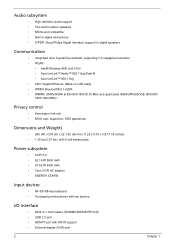
...keyboard • Touchpad pointing device with two buttons I/O interface • Multi-in digital microphone • S/PDIF (Sony/Philips Digital Interface) support for digital speakers Communication • Integrated Acer Crystal Eye webcam, supporting 0.3-megapixel resolution • WLAN: • Intel® ...Wireless WiFi Link 5100 • Acer InviLink™ Nplify™ 802.11b/g/Draft-N • Acer InviLink™ 802.11b/g • LAN: Gigabit Ethernet; Audio subsystem • High-definition audio ...
...keyboard • Touchpad pointing device with two buttons I/O interface • Multi-in digital microphone • S/PDIF (Sony/Philips Digital Interface) support for digital speakers Communication • Integrated Acer Crystal Eye webcam, supporting 0.3-megapixel resolution • WLAN: • Intel® ...Wireless WiFi Link 5100 • Acer InviLink™ Nplify™ 802.11b/g/Draft-N • Acer InviLink™ 802.11b/g • LAN: Gigabit Ethernet; Audio subsystem • High-definition audio ...
Service Guide
Page 13
Chapter 1 3 The exact configuration of the PC depends on the model purchased. • Headphones/speaker/line-out jack with S/PDIF support • Microphone-in jack • Ethernet (RJ-45) port • DC-in jack for AC adapter Environment • Temperature: • Operating: 5°C to 35°C • Non-operating: -20°C to 65°C • Humidity (non-condensing): • Operating: 20% to 80% • Non-operating: 20% to 80% NOTE: The specifications listed above are for reference only.
Chapter 1 3 The exact configuration of the PC depends on the model purchased. • Headphones/speaker/line-out jack with S/PDIF support • Microphone-in jack • Ethernet (RJ-45) port • DC-in jack for AC adapter Environment • Temperature: • Operating: 5°C to 35°C • Non-operating: -20°C to 65°C • Humidity (non-condensing): • Operating: 20% to 80% • Non-operating: 20% to 80% NOTE: The specifications listed above are for reference only.

Service Guide
Page 15
... screen HDD Also called Liquid-Crystal Display (LCD), displays computer output. Lights up when the Num Lock is activated. Front View No. 1 2 3 4 5 6 Chapter 1 Icon Item Acer Crystal Eye webcam Microphone Description Web camera for sound recording. Internal microphone for video communication. Num Lock Caps Lock Lights up when the Caps Lock is active.
... screen HDD Also called Liquid-Crystal Display (LCD), displays computer output. Lights up when the Num Lock is activated. Front View No. 1 2 3 4 5 6 Chapter 1 Icon Item Acer Crystal Eye webcam Microphone Description Web camera for sound recording. Internal microphone for video communication. Num Lock Caps Lock Lights up when the Caps Lock is active.
Service Guide
Page 17
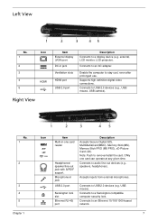
...prolonged use. Note: Push to USB 2.0 devices (e.g. Connects to remove/install the card. Supports high definition digital video connections. Microphone-in -one card can operate at any given time. ONly one card reader Headphones/ speaker/line-out jack with S/PDIF support.... Connects to a Kensington-compatible computer security lock. Accepts inputs from external microphones. Connects to audio line-out devices (e.g., speakers, headphones). Left View No. 1 2 3 4 5 Icon HDMI Right View g Item External...
...prolonged use. Note: Push to USB 2.0 devices (e.g. Connects to remove/install the card. Supports high definition digital video connections. Microphone-in -one card can operate at any given time. ONly one card reader Headphones/ speaker/line-out jack with S/PDIF support.... Connects to a Kensington-compatible computer security lock. Accepts inputs from external microphones. Connects to audio line-out devices (e.g., speakers, headphones). Left View No. 1 2 3 4 5 Icon HDMI Right View g Item External...
Service Guide
Page 30
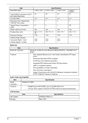
... better RF performance. • USB 2.0 compliant interface. • F/W upgradable via Flash downloads. • Very low power consumption. • Support Coexistence with S/PDF, Line-In and Microphone-In. • 2 stereo ADCs support 16/20/24-bit PCM format recording simultaneously. Audio Codec and Amplifier Item Specification Audio Controller Realtek ALC269X Features •...
... better RF performance. • USB 2.0 compliant interface. • F/W upgradable via Flash downloads. • Very low power consumption. • Support Coexistence with S/PDF, Line-In and Microphone-In. • 2 stereo ADCs support 16/20/24-bit PCM format recording simultaneously. Audio Codec and Amplifier Item Specification Audio Controller Realtek ALC269X Features •...
Service Guide
Page 88
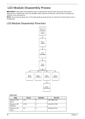
... Panel from Main Unit before proceeding Remove LCD Bezel Remove Camera Module Remove LCD Panel Remove LCD Cable Remove LCD Brackets Remove 3G Antennas Remove Microphone Remove WLAN Antennas Screw List Step Remove LCD Bezel Remove LCD Brackets Remove LCD Panel 78 Screw 2*5 2*2.5 2*3 Quantity 6 4 2 Part No. 86.TG607.004 86.SA107...
... Panel from Main Unit before proceeding Remove LCD Bezel Remove Camera Module Remove LCD Panel Remove LCD Cable Remove LCD Brackets Remove 3G Antennas Remove Microphone Remove WLAN Antennas Screw List Step Remove LCD Bezel Remove LCD Brackets Remove LCD Panel 78 Screw 2*5 2*2.5 2*3 Quantity 6 4 2 Part No. 86.TG607.004 86.SA107...

Service Guide
Page 93
See "Removing the Camera Board" on page 82. 2. Remove the two screws. Screw List Step LCD Panel Disassembly Screw 2x3 Quantity 2 Screw Type Chapter 3 83 Removing the LCD Panel 1. Pull up the microphone. 3.
See "Removing the Camera Board" on page 82. 2. Remove the two screws. Screw List Step LCD Panel Disassembly Screw 2x3 Quantity 2 Screw Type Chapter 3 83 Removing the LCD Panel 1. Pull up the microphone. 3.

Service Guide
Page 96
Pull the microphone/camera cable off the adhesive. 3. Disconnect the LCD connector. 86 Chapter 3 Lift up the protective plastic tab. 4. Removing the FPC Cable 1. Place the panel face down on page 83. 2. See "Removing the LCD Panel" on a clean smooth surface.
Pull the microphone/camera cable off the adhesive. 3. Disconnect the LCD connector. 86 Chapter 3 Lift up the protective plastic tab. 4. Removing the FPC Cable 1. Place the panel face down on page 83. 2. See "Removing the LCD Panel" on a clean smooth surface.

Service Guide
Page 106
3. Apply adhesive and stick the microphone down. 96 Chapter 3
3. Apply adhesive and stick the microphone down. 96 Chapter 3
Service Guide
Page 141
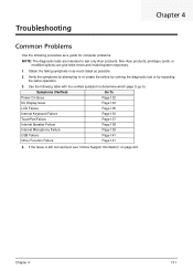
... as possible. 2. If the Issue is still not resolved, see "Online Support Information" on page 241. Chapter 4 131 Non-Acer products, prototype cards, or modified options can give false errors and invalid system responses. 1. Verify the symptoms by repeating the same operation...Issue Page 133 LCD Failure Page 135 Internal Keyboard Failure Page 136 TouchPad Failure Page 137 Internal Speaker Failure Page 138 Internal Microphone Failure Page 139 USB Failure Page 141 Other Function Failure Page 141 4. Troubleshooting Chapter 4 Common Problems Use the following ...
... as possible. 2. If the Issue is still not resolved, see "Online Support Information" on page 241. Chapter 4 131 Non-Acer products, prototype cards, or modified options can give false errors and invalid system responses. 1. Verify the symptoms by repeating the same operation...Issue Page 133 LCD Failure Page 135 Internal Keyboard Failure Page 136 TouchPad Failure Page 137 Internal Speaker Failure Page 138 Internal Microphone Failure Page 139 USB Failure Page 141 Other Function Failure Page 141 4. Troubleshooting Chapter 4 Common Problems Use the following ...
Service Guide
Page 149
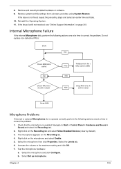
... 3. If the issue is not fixed, repeat the preceding steps and select an earlier time and date. 10. Internal Microphone Failure If the internal Microphone fails, perform the following actions one at a time to correct the problem. Increase the volume to Start Control Panel... Hardware and Sound Sound and select the Recording tab. 2. Test the microphone hardware: a. Chapter 4 139 Select Set up microphone. 8. Reinstall the Operating System. 11. Navigate to the maximum setting and click OK. 7. Select the Levels tab. 6....
... 3. If the issue is not fixed, repeat the preceding steps and select an earlier time and date. 10. Internal Microphone Failure If the internal Microphone fails, perform the following actions one at a time to correct the problem. Increase the volume to Start Control Panel... Hardware and Sound Sound and select the Recording tab. 2. Test the microphone hardware: a. Chapter 4 139 Select Set up microphone. 8. Reinstall the Operating System. 11. Navigate to the maximum setting and click OK. 7. Select the Levels tab. 6....
Service Guide
Page 150
.... When prompted, press any recently added hardware and associated software. 8. f. If the issue is discovered, follow the onscreen information to resolve the problem. 4. Select the microphone type from a known good date using up-to-date software to locate and resolve issues with the computer. c. c. Follow the onscreen prompts to correct the...
.... When prompted, press any recently added hardware and associated software. 8. f. If the issue is discovered, follow the onscreen information to resolve the problem. 4. Select the microphone type from a known good date using up-to-date software to locate and resolve issues with the computer. c. c. Follow the onscreen prompts to correct the...

Service Guide
Page 253
... 33 FRU (Field Replaceable Unit) List 151 H Hard Disk Drive Module Removing 47 Hibernation mode hotkey 13 Hot Keys 11 I Indicators 9 Intermittent Problems 142 Internal Microphone Failure 139 Internal Speaker Failure 138 J Jumper and Connector Locations 147 K Keyboard Removing 56 Keyboard Failure 136 L LCD Bezel Removing 79, 98 LCD Brackets Removing...
... 33 FRU (Field Replaceable Unit) List 151 H Hard Disk Drive Module Removing 47 Hibernation mode hotkey 13 Hot Keys 11 I Indicators 9 Intermittent Problems 142 Internal Microphone Failure 139 Internal Speaker Failure 138 J Jumper and Connector Locations 147 K Keyboard Removing 56 Keyboard Failure 136 L LCD Bezel Removing 79, 98 LCD Brackets Removing...
Service Guide
Page 254
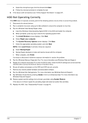
Removing 83, 95 M Main Unit Disassembly Flowchart 54 Mainboard Removing 71 media access on indicator 9 Memory Check 132 Microphone Removing 83, 95 Model Definition 161 N No Display Issue 133 num lock on indicator 9 O ODD Failure 141 Online Support Information 241 P Panel 5 left 5 PC ...hotkey 13 System Block Diagram 4 T Test Compatible Components 231 Thermal Module Removing 74 Touch Pad Failure 137 Troubleshooting Built-in KB Failure 136 Internal Microphone 139 244 Internal Speakers 138 LCD Failure 135 No Display 133 ODD 141 Other Failures 141 Power On 132 Touch Pad 137 USB 141 U Undetermined...
Removing 83, 95 M Main Unit Disassembly Flowchart 54 Mainboard Removing 71 media access on indicator 9 Memory Check 132 Microphone Removing 83, 95 Model Definition 161 N No Display Issue 133 num lock on indicator 9 O ODD Failure 141 Online Support Information 241 P Panel 5 left 5 PC ...hotkey 13 System Block Diagram 4 T Test Compatible Components 231 Thermal Module Removing 74 Touch Pad Failure 137 Troubleshooting Built-in KB Failure 136 Internal Microphone 139 244 Internal Speakers 138 LCD Failure 135 No Display 133 ODD 141 Other Failures 141 Power On 132 Touch Pad 137 USB 141 U Undetermined...

