Service Guide
Page 7
... Using the Keyboard 12 Lock Keys and embedded numeric keypad 12 Windows Keys 13 Hot Keys 14 Special Key 15 Using the System Utilities 16 Acer GridVista (dual-display compatible 16 Hardware Specifications and Configurations 18 System Utilities 27 BIOS Setup Utility 27 Navigating the BIOS Utility 27 Information 28 Main 29 Advanced 30 Security 32 Power 35 Boot 36 AMD 37 Exit 38 BIOS Flash Utility 39 DOS Flash Utility 40 WinFlash Utility 41 Removing HDD Passwords 42 Removing BIOS Passwords 45 Machine Disassembly and Replacement 47 Disassembly...
... Using the Keyboard 12 Lock Keys and embedded numeric keypad 12 Windows Keys 13 Hot Keys 14 Special Key 15 Using the System Utilities 16 Acer GridVista (dual-display compatible 16 Hardware Specifications and Configurations 18 System Utilities 27 BIOS Setup Utility 27 Navigating the BIOS Utility 27 Information 28 Main 29 Advanced 30 Security 32 Power 35 Boot 36 AMD 37 Exit 38 BIOS Flash Utility 39 DOS Flash Utility 40 WinFlash Utility 41 Removing HDD Passwords 42 Removing BIOS Passwords 45 Machine Disassembly and Replacement 47 Disassembly...
Service Guide
Page 9
... Module 137 Replacing the Hard Disk Drive Module 137 Replacing the DIMM Modules 138 Replacing the ODD Module 139 Replacing the Lower Covers 140 Replacing the Express and SD Card Trays 141 Troubleshooting 143 Common Problems 143 Power On Issue 144 No Display Issue 145 Random Loss of BIOS Settings 146 LCD Failure 147 Built-In Keyboard Failure 147 Touchpad Failure 148 Internal Speaker Failure 148 Internal Microphone Failure 150 HDD Not Operating Correctly 151 ODD Failure 152 USB...
... Module 137 Replacing the Hard Disk Drive Module 137 Replacing the DIMM Modules 138 Replacing the ODD Module 139 Replacing the Lower Covers 140 Replacing the Express and SD Card Trays 141 Troubleshooting 143 Common Problems 143 Power On Issue 144 No Display Issue 145 Random Loss of BIOS Settings 146 LCD Failure 147 Built-In Keyboard Failure 147 Touchpad Failure 148 Internal Speaker Failure 148 Internal Microphone Failure 150 HDD Not Operating Correctly 151 ODD Failure 152 USB...

Service Guide
Page 17
... support Unlimited volume control wheel ExpressCard/54 slot Connects to a Kensington-compatible computer security lock. speakers, headphones). Connects to audio line-out devices (e.g. Adjust the volume of the audio-out. Chapter 1 7 audio CD player, stereo walkman). Accepts audio line-in jack Headphones/ speaker/line-out jack with HDMI input. external monitor, LCD projector). Accepts input from external microphones. Connects to an Ethernet 10/100/1000-based network. Accepts one ExpressCard/54 module. Connect to a display device (e.g. Connects to USB 2.0 devices...
... support Unlimited volume control wheel ExpressCard/54 slot Connects to a Kensington-compatible computer security lock. speakers, headphones). Connects to audio line-out devices (e.g. Adjust the volume of the audio-out. Chapter 1 7 audio CD player, stereo walkman). Accepts audio line-in jack Headphones/ speaker/line-out jack with HDMI input. external monitor, LCD projector). Accepts input from external microphones. Connects to an Ethernet 10/100/1000-based network. Accepts one ExpressCard/54 module. Connect to a display device (e.g. Connects to USB 2.0 devices...

Service Guide
Page 20
... can be reset by users. To set to -read status indicators: The front panel indicators are : WLAN, Internet, email, Bluetooth, Arcade and Acer Empowering Technology. They are visible even when the computer cover is closed. Indicates when the hard disk drive is activated. Charging: The light shows amber when the battery is activated. Internet browser (user-Programmable) Email application (user-Programmable) Enables/disables the Bluetooth function. Battery HDD Num Lock Caps Lock Indicates the computer's battery status. Lights up when Num Lock is active. Icon Function Power...
... can be reset by users. To set to -read status indicators: The front panel indicators are : WLAN, Internet, email, Bluetooth, Arcade and Acer Empowering Technology. They are visible even when the computer cover is closed. Indicates when the hard disk drive is activated. Charging: The light shows amber when the battery is activated. Internet browser (user-Programmable) Email application (user-Programmable) Enables/disables the Bluetooth function. Battery HDD Num Lock Caps Lock Indicates the computer's battery status. Lights up when Num Lock is active. Icon Function Power...

Service Guide
Page 24
...+ Icon Function Hotkey help Acer eSettings Management Acer ePower Management Sleep Display toggle Screen blank Touchpad toggle Speaker toggle Brightness up Brightness down Hotkey help Acer eSettings Management Description Displays help on and off to save power. Launches Acer ePower Management in Sleep mode. Press any key to access most of the computer's controls like screen brightness, volume output and the BIOS utility. Puts the computer in Acer Empowering Technology. Switches display output between the display screen, external monitor (if connected) and both. Turns the...
...+ Icon Function Hotkey help Acer eSettings Management Acer ePower Management Sleep Display toggle Screen blank Touchpad toggle Speaker toggle Brightness up Brightness down Hotkey help Acer eSettings Management Description Displays help on and off to save power. Launches Acer ePower Management in Sleep mode. Press any key to access most of the computer's controls like screen brightness, volume output and the BIOS utility. Puts the computer in Acer Empowering Technology. Switches display output between the display screen, external monitor (if connected) and both. Turns the...
Service Guide
Page 37
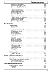
... of the screen. Press F2 to Chapter 4 Troubleshooting when problem arises. Press during POST (when "Press to enter Setup" message is prompted on the bottom of a parameter if it is already properly configured and optimized, and you want to change boot device without entering BIOS Setup Utility, please set to enter multi-boot menu. In this utility. Follow these instructions: • To choose a menu, use the left and right arrow keys. •...
... of the screen. Press F2 to Chapter 4 Troubleshooting when problem arises. Press during POST (when "Press to enter Setup" message is prompted on the bottom of a parameter if it is already properly configured and optimized, and you want to change boot device without entering BIOS Setup Utility, please set to enter multi-boot menu. In this utility. Follow these instructions: • To choose a menu, use the left and right arrow keys. •...

Service Guide
Page 38
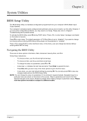
... of the Optical device installed in software construction, standardized by the Open Software Foundation (OSF) as part of the Distributed Computing Environment (DCE). 28 Chapter 2 This field displays the serial number of HDD installed on primary IDE master. Universally Unique Identifier (UUID) is subject to different models. PhoenixBIOS Setup Utility Information Main Advanced Security Power Boot AMD Exit CPU Type: CPU Speed: AMD Turion (tm) X2 Ultra Dual-Core Mobile...
... of the Optical device installed in software construction, standardized by the Open Software Foundation (OSF) as part of the Distributed Computing Environment (DCE). 28 Chapter 2 This field displays the serial number of HDD installed on primary IDE master. Universally Unique Identifier (UUID) is subject to different models. PhoenixBIOS Setup Utility Information Main Advanced Security Power Boot AMD Exit CPU Type: CPU Speed: AMD Turion (tm) X2 Ultra Dual-Core Mobile...
Service Guide
Page 40
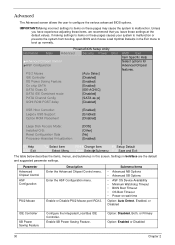
... to malfunction or prevents the system from booting, open BIOS and choose Load Optimal Defaults in the Exit menu to configure the various advanced BIOS options. USB Host Controller: Legacy USB Support: Option ROM Placement [Enabled] [Enabled] [Disabled] Large Disk Access Mode: Installed O/S: Reset Configuration Data Processor Assisted Virtualization: [DOS] [Other] [No] [Enabled] F1 Help ESC Exit ↑↓ Select Item ←→ Select Menu F5/F6 Change Item F9 Setup Default Enter SelectXSubmenu F10 Save and Exit The...
... to malfunction or prevents the system from booting, open BIOS and choose Load Optimal Defaults in the Exit menu to configure the various advanced BIOS options. USB Host Controller: Legacy USB Support: Option ROM Placement [Enabled] [Enabled] [Disabled] Large Disk Access Mode: Installed O/S: Reset Configuration Data Processor Assisted Virtualization: [DOS] [Other] [No] [Enabled] F1 Help ESC Exit ↑↓ Select Item ←→ Select Menu F5/F6 Change Item F9 Setup Default Enter SelectXSubmenu F10 Save and Exit The...
Service Guide
Page 42
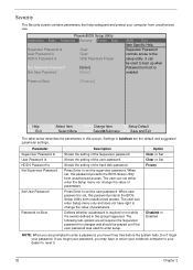
... password for changes and should be used to reset it. 32 Chapter 2 The user can be grayed out if the user password was used to set , this group happened. PhoenixBIOS Setup Utility Information Main Advanced Security Power Boot Supervisor Password Is User Password Is HDD 0 Password Is Clear Clear HDD Password Frozen Set Supervisor Password Set User Password [Enter] [Enter] AMD Exit Item Specific Help Supervisor Password controls acces to set , this screen. Press Enter to boot up when Password on Boot Description Shows the setting of the Supervisor password...
... password for changes and should be used to reset it. 32 Chapter 2 The user can be grayed out if the user password was used to set , this group happened. PhoenixBIOS Setup Utility Information Main Advanced Security Power Boot Supervisor Password Is User Password Is HDD 0 Password Is Clear Clear HDD Password Frozen Set Supervisor Password Set User Password [Enter] [Enter] AMD Exit Item Specific Help Supervisor Password controls acces to set , this screen. Press Enter to boot up when Password on Boot Description Shows the setting of the Supervisor password...

Service Guide
Page 43
... to enable the Password on the screen. 3. After setting the password, the computer sets the User Password parameter to highlight the Set Supervisor Password parameter and press the Enter key. Use the ↑ and ↓ keys to "Set". 4. The Set Password box appears: 2. When you are done, press F10 to save the changes and exit the BIOS Setup Utility. When you have changed the settings, press u to save the changes and exit the BIOS Setup Utility. The...
... to enable the Password on the screen. 3. After setting the password, the computer sets the User Password parameter to highlight the Set Supervisor Password parameter and press the Enter key. Use the ↑ and ↓ keys to "Set". 4. The Set Password box appears: 2. When you are done, press F10 to save the changes and exit the BIOS Setup Utility. When you have changed the settings, press u to save the changes and exit the BIOS Setup Utility. The...

Service Guide
Page 44
... press Enter. 3. Press Enter. After setting the password, the computer sets the User Password parameter to save the changes and exit the BIOS Setup Utility. If desired, you the Setup Warning. When you are done, press F10 to "Set". 5. Type the current password in the Enter New Password field. If the verification is complete after the user presses Enter. The password setting is OK, the screen will show you can enable the Password on boot parameter...
... press Enter. 3. Press Enter. After setting the password, the computer sets the User Password parameter to save the changes and exit the BIOS Setup Utility. If desired, you the Setup Warning. When you are done, press F10 to "Set". 5. Type the current password in the Enter New Password field. If the verification is complete after the user presses Enter. The password setting is OK, the screen will show you can enable the Password on boot parameter...
Service Guide
Page 153
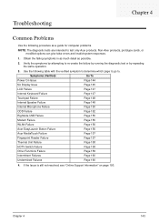
... detail as a guide for computer problems. NOTE: The diagnostic tests are intended to test only Acer products. Symptoms (Verified) Go To Power On Issue Page 144 No Display Issue Page 145 LCD Failure Page 147 Internal Keyboard Failure Page 147 Touchpad Failure Page 148 Internal Speaker Failure Page 148 Internal Microphone Failure Page 150 ODD Failure Page 152 Rightside USB Failure Page 155...
... detail as a guide for computer problems. NOTE: The diagnostic tests are intended to test only Acer products. Symptoms (Verified) Go To Power On Issue Page 144 No Display Issue Page 145 LCD Failure Page 147 Internal Keyboard Failure Page 147 Touchpad Failure Page 148 Internal Speaker Failure Page 148 Internal Microphone Failure Page 150 ODD Failure Page 152 Rightside USB Failure Page 155...

Service Guide
Page 155
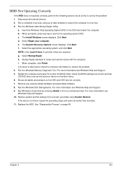
... power and reboot the computer. 4. Make sure the computer has power by removing the power cable and battery and holding down the power button for specific model procedures. 2. Drain any memory cards and CD/DVD discs. Remove any stored power by checking at least one at a time to correct the problem. If the Issue is still not resolved, see "Online Support Information" on page 147. 5. No Display Issue If the Display doesn't work...
... power and reboot the computer. 4. Make sure the computer has power by removing the power cable and battery and holding down the power button for specific model procedures. 2. Drain any memory cards and CD/DVD discs. Remove any stored power by checking at least one at a time to correct the problem. If the Issue is still not resolved, see "Online Support Information" on page 147. 5. No Display Issue If the Display doesn't work...
Service Guide
Page 156
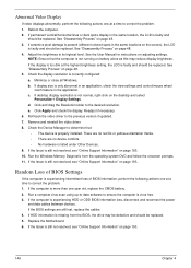
... "Disassembly Process" on page 48. 3. Readjust if necessary. 6. Run the Windows Memory Diagnostic from the BIOS, the drive may reduce display brightness. Click and drag the Resolution slider to ensure the computer is experiencing HDD or ODD BIOS information loss, disconnect and reconnect the power and data cables between devices. Replace the Motherboard. 6. If the computer is virus free. 3. Reboot the computer. 2. Run a complete virus scan using...
... "Disassembly Process" on page 48. 3. Readjust if necessary. 6. Run the Windows Memory Diagnostic from the BIOS, the drive may reduce display brightness. Click and drag the Resolution slider to ensure the computer is experiencing HDD or ODD BIOS information loss, disconnect and reconnect the power and data cables between devices. Replace the Motherboard. 6. If the computer is virus free. 3. Reboot the computer. 2. Run a complete virus scan using...
Service Guide
Page 161
... hardware and associated software. 8. The System Recovery Options screen displays. NOTE: Click Load Drivers if controller drives are set as the first boot device on the HDD and ODD are required. Remove any key to start to resolve the problem. 4. For more information see Windows Help and Support. 10. Run Windows Check Disk by entering chkdsk /r from a known good date using up-to-date software to enter the BIOS Utility. Restore system and file settings from a command prompt. See "Disassembly...
... hardware and associated software. 8. The System Recovery Options screen displays. NOTE: Click Load Drivers if controller drives are set as the first boot device on the HDD and ODD are required. Remove any key to start to resolve the problem. 4. For more information see Windows Help and Support. 10. Run Windows Check Disk by entering chkdsk /r from a known good date using up-to-date software to enter the BIOS Utility. Restore system and file settings from a command prompt. See "Disassembly...
Service Guide
Page 169
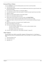
... using System Restore. Check the Device Manager to verify mouse operation. Chapter 4 159 Try an alternative mouse. 2. See the mouse user manual. 3. Try an alternative program to determine that: • The device is properly installed. Reinstall the program experiencing mouse failure. 5. If the Issue is a good connection. Do not replace a non-defective FRUs: 1. Check Test Fixture is listed under Other Devices. 13. Remove any recently added hardware and associated software...
... using System Restore. Check the Device Manager to verify mouse operation. Chapter 4 159 Try an alternative mouse. 2. See the mouse user manual. 3. Try an alternative program to determine that: • The device is properly installed. Reinstall the program experiencing mouse failure. 5. If the Issue is a good connection. Do not replace a non-defective FRUs: 1. Check Test Fixture is listed under Other Devices. 13. Remove any recently added hardware and associated software...
Service Guide
Page 170
... following devices: • Non-Acer devices • Printer, mouse, and other external devices • Battery pack • Hard disk drive • DIMM • CD-ROM/Diskette drive Module • PC Cards 4. Power-off the computer. 2. FRU replacement should be caused by the computer. NOTE: Verify that have nothing to isolate the failing FRU (do not replace any FRU. 3. Visually check them for the system board in loop mode at...
... following devices: • Non-Acer devices • Printer, mouse, and other external devices • Battery pack • Hard disk drive • DIMM • CD-ROM/Diskette drive Module • PC Cards 4. Power-off the computer. 2. FRU replacement should be caused by the computer. NOTE: Verify that have nothing to isolate the failing FRU (do not replace any FRU. 3. Visually check them for the system board in loop mode at...
Service Guide
Page 172
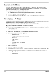
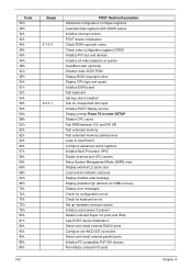
... Load alternate registers with CMOS values Initialize interrupt vectors POST device initialization Check ROM copyright notice Check video configuration against CMOS Initialize PCI bus and devices Initialize all video adapters in system QuietBoot start (optional) Shadow video BIOS ROM Display BIOS copyright notice Display CPU type and speed Initialize EISA board Test keyboard Set key click if enabled Test for unexpected interrupts Initialize POST display service Display prompt Press F2 to enter SETUP Disable CPU cache Test RAM between 512 and 640...
... Load alternate registers with CMOS values Initialize interrupt vectors POST device initialization Check ROM copyright notice Check video configuration against CMOS Initialize PCI bus and devices Initialize all video adapters in system QuietBoot start (optional) Shadow video BIOS ROM Display BIOS copyright notice Display CPU type and speed Initialize EISA board Test keyboard Set key click if enabled Test for unexpected interrupts Initialize POST display service Display prompt Press F2 to enter SETUP Disable CPU cache Test RAM between 512 and 640...

Service Guide
Page 173
... Configure Motherboard Configurable Devices (optional) Initialize BIOS Data Area Enable Non-Maskable Interrupts (NMIs) Initialize Extended BIOS Data Area Test and initialize PS/2 mouse Initialize floppy controller Determine number of day Check key lock Initialize Typematic rate Erase F2 prompt Scan for F2 key stroke Enter SETUP Clear Boot flag Check for SMART Drive (optional) Shadow option ROMs Set up Power Management Initialize security engine (optional) Enable hardware interrupts Determine number of ATA and SCSI drives Set time of ATA drives (optional) Initialize hard-disk controllers...
... Configure Motherboard Configurable Devices (optional) Initialize BIOS Data Area Enable Non-Maskable Interrupts (NMIs) Initialize Extended BIOS Data Area Test and initialize PS/2 mouse Initialize floppy controller Determine number of day Check key lock Initialize Typematic rate Erase F2 prompt Scan for F2 key stroke Enter SETUP Clear Boot flag Check for SMART Drive (optional) Shadow option ROMs Set up Power Management Initialize security engine (optional) Enable hardware interrupts Determine number of ATA and SCSI drives Set time of ATA drives (optional) Initialize hard-disk controllers...
Service Guide
Page 174
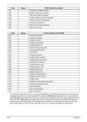
... Initialize the bridge Initialize the CPU Initialize system timer Initialize system I/O Check force recovery boot Checksum BIOS ROM Go to BIOS Set Huge Segment Initialize Multi Processor Initialize OEM special code Initialize PIC and DMA Initialize Memory type Initialize Memory size Shadow Boot Block System memory test Initialize interrupt vectors Initialize Run Time Clock Initialize video Initialize System Management Mode Output one set) has failed. 2E 1020...
... Initialize the bridge Initialize the CPU Initialize system timer Initialize system I/O Check force recovery boot Checksum BIOS ROM Go to BIOS Set Huge Segment Initialize Multi Processor Initialize OEM special code Initialize PIC and DMA Initialize Memory type Initialize Memory size Shadow Boot Block System memory test Initialize interrupt vectors Initialize Run Time Clock Initialize video Initialize System Management Mode Output one set) has failed. 2E 1020...


