
Service Guide
Page 7
... Buttons 9 Touchpad Basics (with fingerprint reader 10 Using the Keyboard 11 Lock Keys and embedded numeric keypad 11 Windows Keys 12 Special Key 13 Using the System Utilities 13 Acer GridVista (dual-display compatible 14 Hardware Specifications and Configurations 15 System Utilities 23 BIOS Setup Utility 23 Navigating the BIOS Utility 23 Information 24 Main 25 Security 26 Boot 29 Exit 30 BIOS Flash Utilities 31 DOS Flash Utility 32 WinFlash Utility 34 Remove HDD/BIOS Password Utilities 36 Miscellaneous Utilities 38 Machine Disassembly and Replacement 41 Disassembly...
... Buttons 9 Touchpad Basics (with fingerprint reader 10 Using the Keyboard 11 Lock Keys and embedded numeric keypad 11 Windows Keys 12 Special Key 13 Using the System Utilities 13 Acer GridVista (dual-display compatible 14 Hardware Specifications and Configurations 15 System Utilities 23 BIOS Setup Utility 23 Navigating the BIOS Utility 23 Information 24 Main 25 Security 26 Boot 29 Exit 30 BIOS Flash Utilities 31 DOS Flash Utility 32 WinFlash Utility 34 Remove HDD/BIOS Password Utilities 36 Miscellaneous Utilities 38 Machine Disassembly and Replacement 41 Disassembly...

Service Guide
Page 8
...Replacing the Thermal Module 104 Replacing the RJ-11 Port 106 Replacing the Mainboard 107 Removing the RTC Battery 109 Replacing the USB Board 109 Replacing the Bluetooth Board 110 Replacing the Modem Module 112 Replacing the Finger Print Reader 115 Replacing the Function Board 117 Replacing the Upper Cover 118 Replacing the LCD Module 121 Replacing the Speaker Module 125 Replacing the Keyboard 126 Replacing the Switch Cover 128 Replacing the Hinge Covers 130 External Module Reassembly Process 131 Replacing the ODD Module 131 Replacing the Hard Disk Drive Module 132 Replacing...
...Replacing the Thermal Module 104 Replacing the RJ-11 Port 106 Replacing the Mainboard 107 Removing the RTC Battery 109 Replacing the USB Board 109 Replacing the Bluetooth Board 110 Replacing the Modem Module 112 Replacing the Finger Print Reader 115 Replacing the Function Board 117 Replacing the Upper Cover 118 Replacing the LCD Module 121 Replacing the Speaker Module 125 Replacing the Keyboard 126 Replacing the Switch Cover 128 Replacing the Hinge Covers 130 External Module Reassembly Process 131 Replacing the ODD Module 131 Replacing the Hard Disk Drive Module 132 Replacing...
Service Guide
Page 9
...-4494P Fingerprint Board 170 LS-4495P USB Board 170 Clearing Password Check and BIOS Recovery 170 Clearing Password Check 171 BIOS Recovery by Crisis Disk 172 FRU (Field Replaceable Unit) List 173 Aspire 4535/4535G/4235 Exploded Diagrams 174 Main Module 174 Base 175 Aspire 4535/4535G/4235 FRU List 176 Screw List 184 Model Definition and Configuration 186 Aspire 4535/4535G/4235 Series 186 Test Compatible Components 211 Microsoft® Windows® Vista Environment Test 212 Online Support Information...
...-4494P Fingerprint Board 170 LS-4495P USB Board 170 Clearing Password Check and BIOS Recovery 170 Clearing Password Check 171 BIOS Recovery by Crisis Disk 172 FRU (Field Replaceable Unit) List 173 Aspire 4535/4535G/4235 Exploded Diagrams 174 Main Module 174 Base 175 Aspire 4535/4535G/4235 FRU List 176 Screw List 184 Model Definition and Configuration 186 Aspire 4535/4535G/4235 Series 186 Test Compatible Components 211 Microsoft® Windows® Vista Environment Test 212 Online Support Information...

Service Guide
Page 14
Display screen Power button HDD Num Lock Also called Liquid-Crystal Display (LCD), displays computer output (Configuration may vary by models). Indicates when the hard disk drive is a description of the functions and features available with this model. Lights up when Caps Lock is activated. Internal microphone for certain models). Turns the computer on and off. Front View No. 1 2 3 4 5 6 Chapter 1 Icon Item Acer Crystal Eye webcam Microphone Description Web camera for video communication (only for sound recording. Caps Lock Lights up when Num...
Display screen Power button HDD Num Lock Also called Liquid-Crystal Display (LCD), displays computer output (Configuration may vary by models). Indicates when the hard disk drive is a description of the functions and features available with this model. Lights up when Caps Lock is activated. Internal microphone for certain models). Turns the computer on and off. Front View No. 1 2 3 4 5 6 Chapter 1 Icon Item Acer Crystal Eye webcam Microphone Description Web camera for video communication (only for sound recording. Caps Lock Lights up when Num...

Service Guide
Page 15
... Volume Down Programmable Key Backup Key Wireless LAN Communication button / Indicator Bluetooth Communication button/indicator Speakers Indicates the computer's battery status. 1. Enables/disables the Bluetooth function. Only one card can operate at any given time. 6 Chapter 1 User-Programmable Launches Acer Backup Management for your hands when you use the computer. Indicates the status of Bluetooth communication. (only for certain models). The left and right buttons function like a computer mouse. Enables/disables the wireless LAN function. Note: Push to remove/install...
... Volume Down Programmable Key Backup Key Wireless LAN Communication button / Indicator Bluetooth Communication button/indicator Speakers Indicates the computer's battery status. 1. Enables/disables the Bluetooth function. Only one card can operate at any given time. 6 Chapter 1 User-Programmable Launches Acer Backup Management for your hands when you use the computer. Indicates the status of Bluetooth communication. (only for certain models). The left and right buttons function like a computer mouse. Enables/disables the wireless LAN function. Note: Push to remove/install...

Service Guide
Page 18
... called easy-launch buttons. Internet browser (user-Programmable) Mail Email application (user-Programmable) Bluetooth communication switch Empowering Technology Enables/disables the Bluetooth function. Easy-Launch Buttons Located beside the keyboard are pre-set the Web browser, mail and programmable buttons, run the Acer Launch Manager. Icon Function Wireless communication switch Web browser Description Enables/disables the wireless function. Note: Do not cover or obstruct the opening of the fan. latch 3 Hard disk bay Houses the computer's hard disk (secured with screws...
... called easy-launch buttons. Internet browser (user-Programmable) Mail Email application (user-Programmable) Bluetooth communication switch Empowering Technology Enables/disables the Bluetooth function. Easy-Launch Buttons Located beside the keyboard are pre-set the Web browser, mail and programmable buttons, run the Acer Launch Manager. Icon Function Wireless communication switch Web browser Description Enables/disables the wireless function. Note: Do not cover or obstruct the opening of the fan. latch 3 Hard disk bay Houses the computer's hard disk (secured with screws...
Service Guide
Page 29
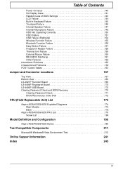
... Interface LVDS Support Color 262,144 Viewing Angle (degree) Min. Super-Multi Combo Module Item Vendor & model name TOSHIBA TSL633B Performance Specification Transfer rate (MB/ 10.8 sec) Buffer Memory 2MB Interface Applicable disc format Loading mechanism Power Requirement Input Voltage Specification PANASONIC UJ880A SONY AD-7590S PLDS DS-8A3S N/A N/A N/A N/A SATA DVD+/-RW Drawer-Type N/A 2MB DC 5 V +/- 5% LCD 14" Item Specification Vendor/model name •...
... Interface LVDS Support Color 262,144 Viewing Angle (degree) Min. Super-Multi Combo Module Item Vendor & model name TOSHIBA TSL633B Performance Specification Transfer rate (MB/ 10.8 sec) Buffer Memory 2MB Interface Applicable disc format Loading mechanism Power Requirement Input Voltage Specification PANASONIC UJ880A SONY AD-7590S PLDS DS-8A3S N/A N/A N/A N/A SATA DVD+/-RW Drawer-Type N/A 2MB DC 5 V +/- 5% LCD 14" Item Specification Vendor/model name •...

Service Guide
Page 33
....000.021.031105 Aspire 4535 Acer 39353164386665643635001EECE1D377 F1 Help Esc Exit Select Item F5/F6 Change Values F9 Setup Defaults Select Menu Enter Select Sub-Menu F10 Save and Exit NOTE: The system information is an identifier standard used in the system. Information The Information screen displays a summary of the Optical device installed in software construction, standardized by the Open Software Foundation (OSF) as part of the system...
....000.021.031105 Aspire 4535 Acer 39353164386665643635001EECE1D377 F1 Help Esc Exit Select Item F5/F6 Change Values F9 Setup Defaults Select Menu Enter Select Sub-Menu F10 Save and Exit NOTE: The system information is an identifier standard used in the system. Information The Information screen displays a summary of the Optical device installed in software construction, standardized by the Open Software Foundation (OSF) as part of the system...

Service Guide
Page 34
... memory size. Memory size is fixed to 4094 MB. This field reports the video Memory size. The function allows the user to create a hidden partition on hard disc drive to store operation system and restore the system to display boot menu message during startup. Sets the system date. The table below describes the parameters in which the SATA controller should operate. Actual values may differ. Enables, disables the system boot from LAN (remote server). Enables, disables D2D Recovery function. Format/Option Format...
... memory size. Memory size is fixed to 4094 MB. This field reports the video Memory size. The function allows the user to create a hidden partition on hard disc drive to store operation system and restore the system to display boot menu message during startup. Sets the system date. The table below describes the parameters in which the SATA controller should operate. Actual values may differ. Enables, disables the system boot from LAN (remote server). Enables, disables D2D Recovery function. Format/Option Format...

Service Guide
Page 35
... to set the Hdd password. Parameter Supervisor Password Is User Password Is SATA Port 0 Disk Status Set Supervisor Password Set User Password Set Hdd Password Power on . The user can enter Setup menu only and cannot change the value of the hard disk password. Press Enter to reset it. 26 Chapter 2 The user can not either enter the Setup menu nor change parameters. When Hdd password is set , this screen. If you have to return your notebook computer to your dealer to set , this password protects the BIOS Setup Utility from unauthorized access.
... to set the Hdd password. Parameter Supervisor Password Is User Password Is SATA Port 0 Disk Status Set Supervisor Password Set User Password Set Hdd Password Power on . The user can enter Setup menu only and cannot change the value of the hard disk password. Press Enter to reset it. 26 Chapter 2 The user can not either enter the Setup menu nor change parameters. When Hdd password is set , this screen. If you have to return your notebook computer to your dealer to set , this password protects the BIOS Setup Utility from unauthorized access.
Service Guide
Page 36
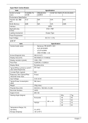
...user or the supervisor password: 1. Use the ↑ and ↓ keys to "Clear". 4. The computer then sets the Supervisor Password parameter to highlight the Set Supervisor Password parameter and press the Enter key. Type a password in the Enter Current Password field and press Enter. 3. Setting a Password Follow these steps: 1. If desired, you have changed the settings, press u to save the changes and exit the BIOS Setup Utility. The Set Supervisor Password box appears: Set Supervisor Password Enter New Password [ ] Confirm New Password [ ] 2. Removing a Password...
...user or the supervisor password: 1. Use the ↑ and ↓ keys to "Clear". 4. The computer then sets the Supervisor Password parameter to highlight the Set Supervisor Password parameter and press the Enter key. Type a password in the Enter Current Password field and press Enter. 3. Setting a Password Follow these steps: 1. If desired, you have changed the settings, press u to save the changes and exit the BIOS Setup Utility. The Set Supervisor Password box appears: Set Supervisor Password Enter New Password [ ] Confirm New Password [ ] 2. Removing a Password...

Service Guide
Page 37
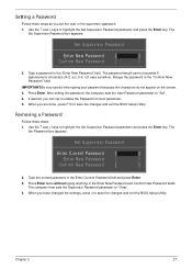
... Chapter 2 Changing a Password 1. Use the ↑ and ↓ keys to save the changes and exit the BIOS Setup Utility. If the current password entered does not match the actual current password, the screen will display as following message. Press Enter. Retype the password in the Confirm New Password field. 4. The Set Password box appears. After setting the password, the computer sets the User Password parameter to "Set". 5. Setup Warning Invalid Password. [Continue] If the new password and confirm new password strings...
... Chapter 2 Changing a Password 1. Use the ↑ and ↓ keys to save the changes and exit the BIOS Setup Utility. If the current password entered does not match the actual current password, the screen will display as following message. Press Enter. Retype the password in the Confirm New Password field. 4. The Set Password box appears. After setting the password, the computer sets the User Password parameter to "Set". 5. Setup Warning Invalid Password. [Continue] If the new password and confirm new password strings...
Service Guide
Page 148
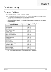
... "Online Support Information" on page 241. Symptoms (Verified) Go To Power On Issue Page 140 No Display Issue Page 141 LCD Failure Page 144 Internal Keyboard Failure Page 145 Touchpad Failure Page 146 Internal Speaker Failure Page 147 Internal Microphone Failure Page 149 ODD Failure Page 151 Rightside USB Failure Page 154 WLAN Failure Page 155 Bluetooth Failure Page 156 Easy Button Failure...
... "Online Support Information" on page 241. Symptoms (Verified) Go To Power On Issue Page 140 No Display Issue Page 141 LCD Failure Page 144 Internal Keyboard Failure Page 145 Touchpad Failure Page 146 Internal Speaker Failure Page 147 Internal Microphone Failure Page 149 ODD Failure Page 151 Rightside USB Failure Page 154 WLAN Failure Page 155 Bluetooth Failure Page 156 Easy Button Failure...
Service Guide
Page 150
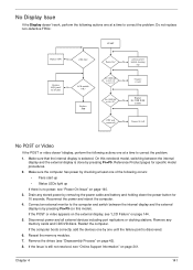
...: START Replace CPU No CPU OK? Replace M/B Power On? Disconnect power and all external devices including port replicators or docking stations. goto no power, see "LCD Failure" on page 241. Replace LCD panel/ No LCD cable LCD module OK? DDRRAM module well No connected? Drain any memory cards and CD/DVD discs. If the computer boots correctly, add the devices one by pressing Fn+F5. DDRRAM module OK? Connect an external monitor to the computer and switch between the internal display and the external display is...
...: START Replace CPU No CPU OK? Replace M/B Power On? Disconnect power and all external devices including port replicators or docking stations. goto no power, see "LCD Failure" on page 241. Replace LCD panel/ No LCD cable LCD module OK? DDRRAM module well No connected? Drain any memory cards and CD/DVD discs. If the computer boots correctly, add the devices one by pressing Fn+F5. DDRRAM module OK? Connect an external monitor to the computer and switch between the internal display and the external display is...

Service Guide
Page 159
... see Windows Help and Support. 9. Disconnect all cables and jumpers on the HDD and ODD are required. Run the Windows Vista Startup Repair Utility: a. The Install Windows screen displays. d. Select Repair your computer. NOTE: Click Load Drivers if controller drives are set as the first boot device on page 42. 150 Chapter 4 Select Startup Repair. Run the Windows Memory Diagnostic Tool. Ensure all external devices. 2. Run the Windows Disk Defragmenter. For more information see Windows Help and Support. 10. Restore system...
... see Windows Help and Support. 9. Disconnect all cables and jumpers on the HDD and ODD are required. Run the Windows Vista Startup Repair Utility: a. The Install Windows screen displays. d. Select Repair your computer. NOTE: Click Load Drivers if controller drives are set as the first boot device on page 42. 150 Chapter 4 Select Startup Repair. Run the Windows Memory Diagnostic Tool. Ensure all external devices. 2. Run the Windows Disk Defragmenter. For more information see Windows Help and Support. 10. Restore system...

Service Guide
Page 162
... F2 to Start´ Control Panel´ System and Maintenance´ System´ Device Manager. See "Disassembly Process" on the drive, motherboard, and cables. Check for the other discs. Test the drive using other ATA Devices shown if applicable. Turn off the power and remove the cover to inspect the connections to the ODD. a. Check for bent or broken pins on the drive, motherboard, and cables. Chapter 4 153 Navigate to enter the BIOS Utility. 2. c. Click...
... F2 to Start´ Control Panel´ System and Maintenance´ System´ Device Manager. See "Disassembly Process" on the drive, motherboard, and cables. Check for the other discs. Test the drive using other ATA Devices shown if applicable. Turn off the power and remove the cover to inspect the connections to the ODD. a. Check for bent or broken pins on the drive, motherboard, and cables. Chapter 4 153 Navigate to enter the BIOS Utility. 2. c. Click...
Service Guide
Page 169
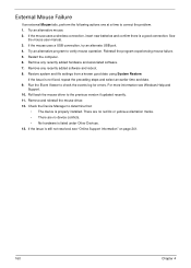
... experiencing mouse failure. 5. Remove any recently added hardware and associated software. 7. Restore system and file settings from a known good date using System Restore. Run the Event Viewer to determine that: • The device is properly installed. Check the Device Manager to check the events log for errors. Roll back the mouse driver to correct the problem. 1. See the mouse user manual. 3. Remove any recently added software and reboot. 8. If the mouse uses a wireless connection, insert new batteries and...
... experiencing mouse failure. 5. Remove any recently added hardware and associated software. 7. Restore system and file settings from a known good date using System Restore. Run the Event Viewer to determine that: • The device is properly installed. Check the Device Manager to check the events log for errors. Roll back the mouse driver to correct the problem. 1. See the mouse user manual. 3. Remove any recently added software and reboot. 8. If the mouse uses a wireless connection, insert new batteries and...
Service Guide
Page 171
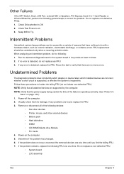
... removed devices one at a time. Check Drive whether is ok. 3. When analyzing an intermittent problem, do not replace any FRU. 3. If no more errors. Follow these procedures to Try. Visually check them for the system board in -1 Card Reader or Volume Wheel fail, perform the following devices: • Non-Acer devices • Printer, mouse, and other external devices • Battery pack • Hard disk drive • DIMM • CD-ROM/Diskette drive Module...
... removed devices one at a time. Check Drive whether is ok. 3. When analyzing an intermittent problem, do not replace any FRU. 3. If no more errors. Follow these procedures to Try. Visually check them for the system board in -1 Card Reader or Volume Wheel fail, perform the following devices: • Non-Acer devices • Printer, mouse, and other external devices • Battery pack • Hard disk drive • DIMM • CD-ROM/Diskette drive Module...

Service Guide
Page 173
... vectors POST device initialization Check ROM copyright notice Check video configuration against CMOS Initialize PCI bus and devices Initialize all video adapters in system QuietBoot start (optional) Shadow video BIOS ROM Display BIOS copyright notice Display CPU type and speed Initialize EISA board Test keyboard Set key click if enabled Test for unexpected interrupts Initialize POST display service Display prompt "Press F2 to enter SETUP" Disable CPU cache Test RAM between 512 and 640 KB Test extended memory Test extended memory address lines...
... vectors POST device initialization Check ROM copyright notice Check video configuration against CMOS Initialize PCI bus and devices Initialize all video adapters in system QuietBoot start (optional) Shadow video BIOS ROM Display BIOS copyright notice Display CPU type and speed Initialize EISA board Test keyboard Set key click if enabled Test for unexpected interrupts Initialize POST display service Display prompt "Press F2 to enter SETUP" Disable CPU cache Test RAM between 512 and 640 KB Test extended memory Test extended memory address lines...

Service Guide
Page 252
... Device Configuration 27 Power 29 Save and Exit 30 Security 26 System Security 30 Bluetooth Module Removing 76 Board Layout Top View 167 C Camera Module 90 Common Problems 140 computer on indicator 9 CPU 86 D DIMM Modules Removing 50 Display 4 E EasyTouch Failure 157 Euro 13 External Module Disassembly Flowchart 43 F Features 1 Finger Print Reader Index Removing 71 Fingerprint Reader Failure 158 Flash Utility 31 FPC Cable 93 FRU (Field Replaceable Unit) List 173 Function Board Removing 70, 117 H HDD Removing 51 Hinge Covers Removing...
... Device Configuration 27 Power 29 Save and Exit 30 Security 26 System Security 30 Bluetooth Module Removing 76 Board Layout Top View 167 C Camera Module 90 Common Problems 140 computer on indicator 9 CPU 86 D DIMM Modules Removing 50 Display 4 E EasyTouch Failure 157 Euro 13 External Module Disassembly Flowchart 43 F Features 1 Finger Print Reader Index Removing 71 Fingerprint Reader Failure 158 Flash Utility 31 FPC Cable 93 FRU (Field Replaceable Unit) List 173 Function Board Removing 70, 117 H HDD Removing 51 Hinge Covers Removing...


