
Service Guide
Page 7
... Using the Keyboard 15 Lock Keys and embedded numeric keypad 15 Windows Keys 15 Hot Keys 16 Special Key 17 Hardware Specifications and Configurations 19 Chapter 2 System Utilities 29 BIOS Setup Utility 29 Navigating the BIOS Utility 30 Information 31 Main 32 Security 34 Boot 38 Exit 39 BIOS Flash Utility 40 Chapter 3 Machine Disassembly and Replacement 41 General Information 42 Before You Begin 42 Disassembly Procedure Flowchart 43 Removing the Battery Pack 45 Removing the Memory/the HDD Module/the Wireless LAN Card...
... Using the Keyboard 15 Lock Keys and embedded numeric keypad 15 Windows Keys 15 Hot Keys 16 Special Key 17 Hardware Specifications and Configurations 19 Chapter 2 System Utilities 29 BIOS Setup Utility 29 Navigating the BIOS Utility 30 Information 31 Main 32 Security 34 Boot 38 Exit 39 BIOS Flash Utility 40 Chapter 3 Machine Disassembly and Replacement 41 General Information 42 Before You Begin 42 Disassembly Procedure Flowchart 43 Removing the Battery Pack 45 Removing the Memory/the HDD Module/the Wireless LAN Card...

Service Guide
Page 20
.... Indicates the status of Bluetooth communication. Launch Keys Located at http://printer1.blogspot.com To set to run the Acer Launch Manager. 12 Chapter 1 Download Free Service Manual at the upper-right, above the keyboard are : mail, Web browser, Acer Empowering key " " and one user-programmable button. The power, battery and wireless communication status indicators are visible even when the LCD display is activated. Please see "Acer eManager". Media Activity Bluetooth Wireless LAN Battery Power Indicates when the hard disc or optical drive is being charged. Lights...
.... Indicates the status of Bluetooth communication. Launch Keys Located at http://printer1.blogspot.com To set to run the Acer Launch Manager. 12 Chapter 1 Download Free Service Manual at the upper-right, above the keyboard are : mail, Web browser, Acer Empowering key " " and one user-programmable button. The power, battery and wireless communication status indicators are visible even when the LCD display is activated. Please see "Acer eManager". Media Activity Bluetooth Wireless LAN Battery Power Indicates when the hard disc or optical drive is being charged. Lights...
Service Guide
Page 27
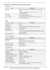
... control System Memory Item Memory controller Memory size DIMM socket number Supports memory size per socket Supports maximum memory size Supports DIMM type Supports DIMM Speed Supports DIMM voltage Supports DIMM package Memory module combinations Specification Phneoix 3A03 PMC PM39LV040, 512KX8 CMOS Boot Block Flash Memory 512KB Flash BIOS 32-pin PLCC ACPI 1.0b, PC Card 95, SM BIOS 2.3, IEEE1284-ECP/EPP, PCI 2.2, PnP 1.0a, DMI 2.0, PS/2 keyboard and mouse, USB 2.0, VGA BIOS, CD-ROM bootable, IEEE 1394 Set by setup manual Specification Built-in CPU...
... control System Memory Item Memory controller Memory size DIMM socket number Supports memory size per socket Supports maximum memory size Supports DIMM type Supports DIMM Speed Supports DIMM voltage Supports DIMM package Memory module combinations Specification Phneoix 3A03 PMC PM39LV040, 512KX8 CMOS Boot Block Flash Memory 512KB Flash BIOS 32-pin PLCC ACPI 1.0b, PC Card 95, SM BIOS 2.3, IEEE1284-ECP/EPP, PCI 2.2, PnP 1.0a, DMI 2.0, PS/2 keyboard and mouse, USB 2.0, VGA BIOS, CD-ROM bootable, IEEE 1394 Set by setup manual Specification Built-in CPU...
Service Guide
Page 35
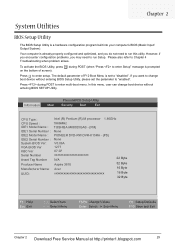
... this menu, user can change boot device without entering BIOS SETUP Utility. Press during POST (when "Press to "disabled". To activate the BIOS Utility, press m during POST to run Setup. Information Main PhoenixBIOS Setup Utility Security Boot Exit CPU Type : CPU Speed : IDE1 Model Name : IDE1 Serial Number : IDE2 Model Name : IDE2 Serial Number : System BIOS Ver: VGA BIOS Ver KBC Ver Serial Number Asset Tag Number Produce Name Manufacturer Name: UUID: Intel (R) Pentium (R) M processor 1.86GHz 1866MHz TOSHIBA MK8025GAS - (PM) None PIONEER DVD...
... this menu, user can change boot device without entering BIOS SETUP Utility. Press during POST (when "Press to "disabled". To activate the BIOS Utility, press m during POST to run Setup. Information Main PhoenixBIOS Setup Utility Security Boot Exit CPU Type : CPU Speed : IDE1 Model Name : IDE1 Serial Number : IDE2 Model Name : IDE2 Serial Number : System BIOS Ver: VGA BIOS Ver KBC Ver Serial Number Asset Tag Number Produce Name Manufacturer Name: UUID: Intel (R) Pentium (R) M processor 1.86GHz 1866MHz TOSHIBA MK8025GAS - (PM) None PIONEER DVD...
Service Guide
Page 37
... displays the asset tag number of HDD installed on secondary IDE master. The hard disk drive or optical drive model name is presenting. This field displays the serial number of the system. This field shows product name of the system. This will be visible only when an internal LAN device is automatically detected by the system. This field displays the VGA firmware version of the system. F9 Setup Defaults...
... displays the asset tag number of HDD installed on secondary IDE master. The hard disk drive or optical drive model name is presenting. This field displays the serial number of the system. This field shows product name of the system. This will be visible only when an internal LAN device is automatically detected by the system. This field displays the VGA firmware version of the system. F9 Setup Defaults...

Service Guide
Page 39
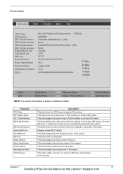
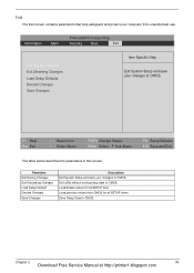
... hard disc drive to store operation system and restore the system to 640MB This field reports the memory size of the system. Both: Simultaneously enable both the integrated LCD screen and the system's external video port (for an external CRT or projector). The hours are the default and suggested parameter settings. If any display device is connected, the power on display Network Boot F12 Boot Menu D2D Recovery Description Format/Option Sets the system time. Option: Auto or Both Enables, disables...
... hard disc drive to store operation system and restore the system to 640MB This field reports the memory size of the system. Both: Simultaneously enable both the integrated LCD screen and the system's external video port (for an external CRT or projector). The hours are the default and suggested parameter settings. If any display device is connected, the power on display Network Boot F12 Boot Menu D2D Recovery Description Format/Option Sets the system time. Option: Auto or Both Enables, disables...
Service Guide
Page 41
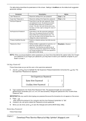
... sub-options are done, press u to set the user password. If you forget your password, you may have right to change the value of the Supervisor password Press Enter to "Set". 4. Press e. After setting the password, the computer sets the User Password parameter to set the supervisor password. Settings in the "Confirm New Password" field. Enables or disables primary hard disk security function. The Set Supervisor Password box appears: 2. When user password is set , this password protects the BIOS Setup Utility from unauthorized access. Type a password...
... sub-options are done, press u to set the user password. If you forget your password, you may have right to change the value of the Supervisor password Press Enter to "Set". 4. Press e. After setting the password, the computer sets the User Password parameter to set the supervisor password. Settings in the "Confirm New Password" field. Enables or disables primary hard disk security function. The Set Supervisor Password box appears: 2. When user password is set , this password protects the BIOS Setup Utility from unauthorized access. Type a password...

Service Guide
Page 42
... current password, the screen will display as following. Changing a Password 1. Type the current password in the Enter Current Password field and press e. 3. Press e twice without typing anything in the Enter New Password and Confirm New Password fields. The computer then sets the Supervisor Password parameter to "Set". 5. When you the Setup Warning. 36 Chapter 2 Download Free Service Manual at http://printer1.blogspot.com If the verification is complete after the user presses u. Use the w and y keys...
... current password, the screen will display as following. Changing a Password 1. Type the current password in the Enter Current Password field and press e. 3. Press e twice without typing anything in the Enter New Password and Confirm New Password fields. The computer then sets the Supervisor Password parameter to "Set". 5. When you the Setup Warning. 36 Chapter 2 Download Free Service Manual at http://printer1.blogspot.com If the verification is complete after the user presses u. Use the w and y keys...
Service Guide
Page 45
... Setup and save your changes to CMOS. Exit utility without saving setup data to CMOS. Load previous values from unauthorized use. F1 Help Esc Exit ↑ ↓ Select Item ← → Select Menu F5/F6 Change Values Enter Select 4 Sub-Menu F9 Setup Defaults F10 Save and Exit The table below describes the parameters in this screen. Load default values for all SETUP item. Chapter 2 39 Download Free Service Manual...
... Setup and save your changes to CMOS. Exit utility without saving setup data to CMOS. Load previous values from unauthorized use. F1 Help Esc Exit ↑ ↓ Select Item ← → Select Menu F5/F6 Change Values Enter Select 4 Sub-Menu F9 Setup Defaults F10 Save and Exit The table below describes the parameters in this screen. Load default values for all SETUP item. Chapter 2 39 Download Free Service Manual...
Service Guide
Page 46
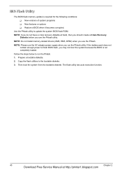
... following conditions: T New versions of system programs T New features or options T Restore a BIOS when it becomes corrupted. The flash utility has auto-execution function. 40 Chapter 2 Download Free Service Manual at hand, then you should create a Crisis Recovery Diskette before you use the AC adaptor power supply when you do not have a crisis recovery diskette at http://printer1.blogspot.com Prepare a bootable diskette. 2. BIOS Flash Utility The BIOS flash memory update is not completely...
... following conditions: T New versions of system programs T New features or options T Restore a BIOS when it becomes corrupted. The flash utility has auto-execution function. 40 Chapter 2 Download Free Service Manual at hand, then you should create a Crisis Recovery Diskette before you use the AC adaptor power supply when you do not have a crisis recovery diskette at http://printer1.blogspot.com Prepare a bootable diskette. 2. BIOS Flash Utility The BIOS flash memory update is not completely...

Service Guide
Page 49
... to remove the system board, you on rear side H*3 HDD Cover Wireless LAN Card O*4 HDD Module M*4 HDD Bracket HDD Lower Case Assembly O*2 RTC Battery Bluetooth Module Upper Case Assembly Microphone Lower Case *2 Speaker Set Main Board Assembly Upper Case Touchpad Assembly N*3 C*1 86.9A353.3R0*2 D*2 North Bridge Plate CPU Heatsink 86.9A353.3R0*2 O*2 Modem Board Fan Touchpad Bracket Touchpad CPU ODD Module G*2 ODD ODD Bracket Chapter 3 43 Download Free Service Manual at http://printer1.blogspot.com Start Battery Middle Cover H*2 DIMM Cover Memory P*1 Keyboard...
... to remove the system board, you on rear side H*3 HDD Cover Wireless LAN Card O*4 HDD Module M*4 HDD Bracket HDD Lower Case Assembly O*2 RTC Battery Bluetooth Module Upper Case Assembly Microphone Lower Case *2 Speaker Set Main Board Assembly Upper Case Touchpad Assembly N*3 C*1 86.9A353.3R0*2 D*2 North Bridge Plate CPU Heatsink 86.9A353.3R0*2 O*2 Modem Board Fan Touchpad Bracket Touchpad CPU ODD Module G*2 ODD ODD Bracket Chapter 3 43 Download Free Service Manual at http://printer1.blogspot.com Start Battery Middle Cover H*2 DIMM Cover Memory P*1 Keyboard...

Service Guide
Page 62
... an error occurs with the internal diskette drive, reconnect the diskette connector on the System board. Do the following to isolate the problem to be tested. Boot from the diagnostics diskette and start the diagnostics program. 2. See if CD-ROM Test is to a controller, driver, or diskette. Replace the external diskette drive/CD-ROM module. 3. If the internal keyboard does not work or an unexpected character appears, make sure...
... an error occurs with the internal diskette drive, reconnect the diskette connector on the System board. Do the following to isolate the problem to be tested. Boot from the diagnostics diskette and start the diagnostics program. 2. See if CD-ROM Test is to a controller, driver, or diskette. Replace the external diskette drive/CD-ROM module. 3. If the internal keyboard does not work or an unexpected character appears, make sure...

Service Guide
Page 67
... Configuration Error") Memory Error at http://printer1.blogspot.com Error Message List Error Messages FRU/Action in BIOS Setup Utility. System timer error RTC battery Run BIOS Setup Utility to reconfigure system time, then reboot system. CPU BIOS Update Code Mismatch 2. Keyboard locked - System CMOS checksum bad - System board Chapter 4 61 Download Free Service Manual at xxxx:xxxx:xxxxh (R:xxxxh, W:xxxxh) Real Time Clock Error CMOS Battery Bad CMOS Checksum Error System disabled. Keyboard error see "Keyboard or Auxiliary Input Device Check" on page 56. Battery...
... Configuration Error") Memory Error at http://printer1.blogspot.com Error Message List Error Messages FRU/Action in BIOS Setup Utility. System timer error RTC battery Run BIOS Setup Utility to reconfigure system time, then reboot system. CPU BIOS Update Code Mismatch 2. Keyboard locked - System CMOS checksum bad - System board Chapter 4 61 Download Free Service Manual at xxxx:xxxx:xxxxh (R:xxxxh, W:xxxxh) Real Time Clock Error CMOS Battery Bad CMOS Checksum Error System disabled. Keyboard error see "Keyboard or Auxiliary Input Device Check" on page 56. Battery...

Service Guide
Page 71
... devices Initialize all video adapters in system QuietBoot start (optional) Shadow video BIOS ROM Display BIOS copyright notice Display CPU type and speed Initialize EISA board Test keyboard Set key click if enabled Test for unexpected interrupts Initialize POST display service Display prompt "Press F2 to enter SETUP" Disable CPU cache Test RAM between 512 and 640 KB Test extended memory Test extended memory address lines Jump to User Patch1 Configure advanced cache registers Initialize Multi Processor APIC Enable external and CPU caches Setup...
... devices Initialize all video adapters in system QuietBoot start (optional) Shadow video BIOS ROM Display BIOS copyright notice Display CPU type and speed Initialize EISA board Test keyboard Set key click if enabled Test for unexpected interrupts Initialize POST display service Display prompt "Press F2 to enter SETUP" Disable CPU cache Test RAM between 512 and 640 KB Test extended memory Test extended memory address lines Jump to User Patch1 Configure advanced cache registers Initialize Multi Processor APIC Enable external and CPU caches Setup...

Service Guide
Page 72
... option ROMs Set up Power Management Initialize security engine (optional) Enable hardware interrupts Determine number of ATA and SCSI drives Set time of ATA drives (optional) Initialize hard-disk controllers Initialize local-bus hard-disk controllers Jump to boot with INT 19 Initialize POST Error Manager (PEM) Initialize error logging Initialize error display function Initialize system error handler PnPnd dual CMOS (optional) Initialize notebook docking (optional) Initialize notebook docking late Force check (optional) Extended checksum (optional) Chapter 4 Download Free Service Manual...
... option ROMs Set up Power Management Initialize security engine (optional) Enable hardware interrupts Determine number of ATA and SCSI drives Set time of ATA drives (optional) Initialize hard-disk controllers Initialize local-bus hard-disk controllers Jump to boot with INT 19 Initialize POST Error Manager (PEM) Initialize error logging Initialize error display function Initialize system error handler PnPnd dual CMOS (optional) Initialize notebook docking (optional) Initialize notebook docking late Force check (optional) Extended checksum (optional) Chapter 4 Download Free Service Manual...
Service Guide
Page 73
... I/O Check force recovery boot Checksum BIOS ROM Go to BIOS Set Huge Segment Initialize Multi Processor Initialize OEM special code Initialize PIC and DMA Initialize Memory type Initialize Memory size Shadow Boot Block System memory test Initialize interrupt vectors Initialize Run Time Clock Initialize video Initialize System Management Mode Output one beep before boot Boot to Mini DOS Clear Huge Segment Boot to Full DOS Chapter 4 67 Download Free Service Manual at http...
... I/O Check force recovery boot Checksum BIOS ROM Go to BIOS Set Huge Segment Initialize Multi Processor Initialize OEM special code Initialize PIC and DMA Initialize Memory type Initialize Memory size Shadow Boot Block System memory test Initialize interrupt vectors Initialize Run Time Clock Initialize video Initialize System Management Mode Output one beep before boot Boot to Mini DOS Clear Huge Segment Boot to Full DOS Chapter 4 67 Download Free Service Manual at http...

Service Guide
Page 74
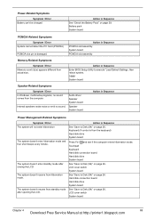
... inverter LCD System board LCD inverter ID LCD inverter LCD cable LCD System board Indicator-Related Symptoms Symptom / Error Action in Sequence Enter BIOS Utility to -FRU Error Message LCD-Related Symptoms Symptom / Error LCD backlight doesn't work ). Battery pack Power adapter Hard drive & battery connection board System board Power source (battery pack and power adapter). Hold and press the power switch for more than 4 seconds. Action in Sequence Indicator incorrectly remains off . See "Power System Check" on page 57. System board 68 Chapter 4 Download Free Service Manual...
... inverter LCD System board LCD inverter ID LCD inverter LCD cable LCD System board Indicator-Related Symptoms Symptom / Error Action in Sequence Enter BIOS Utility to -FRU Error Message LCD-Related Symptoms Symptom / Error LCD backlight doesn't work ). Battery pack Power adapter Hard drive & battery connection board System board Power source (battery pack and power adapter). Hold and press the power switch for more than 4 seconds. Action in Sequence Indicator incorrectly remains off . See "Power System Check" on page 57. System board 68 Chapter 4 Download Free Service Manual...
Service Guide
Page 75
.... LCD cover switch System board Chapter 4 69 Download Free Service Manual at http://printer1.blogspot.com Battery pack System board PCMCIA-Related Symptoms Symptom / Error System cannot detect the PC Card (PCMCIA) PCMCIA slot pin is from actual size. Internal speakers make noise or emit no sound comes from standby mode after closing the LCD The system doesn't resume from hibernation mode. Touchpad Keyboard Hard disk connection board Hard disk drive System board See "Save to execute "Load Default Settings, then reboot...
.... LCD cover switch System board Chapter 4 69 Download Free Service Manual at http://printer1.blogspot.com Battery pack System board PCMCIA-Related Symptoms Symptom / Error System cannot detect the PC Card (PCMCIA) PCMCIA slot pin is from actual size. Internal speakers make noise or emit no sound comes from standby mode after closing the LCD The system doesn't resume from hibernation mode. Touchpad Keyboard Hard disk connection board Hard disk drive System board See "Save to execute "Load Default Settings, then reboot...
Service Guide
Page 76
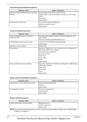
... the installed devices. USB does not work correctly. Touchpad board System board Modem-Related Symptoms Symptom / Error Action in Sequence Internal modem does not work correctly Print problems. Serial or parallel port device problems. Action in the "Onboard Devices Configuration" of BIOS Setup Utility is set to execute "Load Default Settings", then reboot system. Reconnect hard disk/CD-ROM/diskette drives. Press Fn+F5, LCD/CRT/Both display switching System board System board Ensure the "Parallel Port" in Sequence Enter BIOS Setup Utility to Enabled. Touchpad does...
... the installed devices. USB does not work correctly. Touchpad board System board Modem-Related Symptoms Symptom / Error Action in Sequence Internal modem does not work correctly Print problems. Serial or parallel port device problems. Action in the "Onboard Devices Configuration" of BIOS Setup Utility is set to execute "Load Default Settings", then reboot system. Reconnect hard disk/CD-ROM/diskette drives. Press Fn+F5, LCD/CRT/Both display switching System board System board Ensure the "Parallel Port" in Sequence Enter BIOS Setup Utility to Enabled. Touchpad does...
Service Guide
Page 77
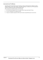
Run the advanced diagnostic test for the system board in loop mode at http://printer1.blogspot.com Chapter 4 71 Download Free Service Manual at least 10 times. 2. If any FRU. 3. If no more errors. When analyzing an intermittent problem, do not replace any error is detected, do the following: 1. FRU replacement should be caused by a variety of reasons that there are no...
Run the advanced diagnostic test for the system board in loop mode at http://printer1.blogspot.com Chapter 4 71 Download Free Service Manual at least 10 times. 2. If any FRU. 3. If no more errors. When analyzing an intermittent problem, do not replace any error is detected, do the following: 1. FRU replacement should be caused by a variety of reasons that there are no...


