
User Manual
Page 4
... Con guration 68 3.4.3 South Bridge Con guration 70 3.4.4 Storage Con guration 71 3.4.5 Super IO Con guration 72 3.4.6 ACPI Con guration 73 3.4.7 USB Con guration 74 3.5 Hardware Health Event Monitoring Screen 75 3.6 Boot Screen 76 3.7 Security Screen 77 3.8 Exit Screen 78 4 Software Support 79 4.1 Install Operating System 79 4.2 Support CD Information 79 4.2.1 Running...
... Con guration 68 3.4.3 South Bridge Con guration 70 3.4.4 Storage Con guration 71 3.4.5 Super IO Con guration 72 3.4.6 ACPI Con guration 73 3.4.7 USB Con guration 74 3.5 Hardware Health Event Monitoring Screen 75 3.6 Boot Screen 76 3.7 Security Screen 77 3.8 Exit Screen 78 4 Software Support 79 4.1 Install Operating System 79 4.2 Support CD Information 79 4.2.1 Running...
User Manual
Page 8
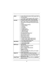
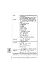
... Version), CyberLink MediaEspresso 6.5 Trial, ASRock Software Suite (CyberLink DVD Suite - Front panel audio connector - 3 x USB 2.0 headers (support 6 USB 2.0 ports) - 1 x USB 3.0 header (supports 2 USB 3.0 ports) - 1 x Dr.... Debug (7-Segment Debug LED) - 1 x Clear CMOS Switch with LED - 1 x Power Switch with LED - 1 x Reset Switch with GUI support - CPU/Chassis/Power FAN connector - 24 pin ATX power connector - 8 pin 12V power connector - Supports "Plug and Play" - ASRock Instant Boot...
... Version), CyberLink MediaEspresso 6.5 Trial, ASRock Software Suite (CyberLink DVD Suite - Front panel audio connector - 3 x USB 2.0 headers (support 6 USB 2.0 ports) - 1 x USB 3.0 header (supports 2 USB 3.0 ports) - 1 x Dr.... Debug (7-Segment Debug LED) - 1 x Clear CMOS Switch with LED - 1 x Power Switch with LED - 1 x Reset Switch with GUI support - CPU/Chassis/Power FAN connector - 24 pin ATX power connector - 8 pin 12V power connector - Supports "Plug and Play" - ASRock Instant Boot...

User Manual
Page 9
...- CPU/Chassis/Power Fan Tachometer - FCC, CE, WHQL - We are not responsible for possible damage caused by CPU Temperature) - - ASRock XFast USB (see CAUTION 16) - ErP/EuP Ready (ErP/EuP ready power supply is required) (see CAUTION 17) - CPU Frequency Stepless Control (.... Lucid Virtu (see CAUTION 14) - Hybrid Booster: - Combo Cooler Option (C.C.O.) (see CAUTION 12) - Chassis Temperature Sensing - ASRock SmartView (see CAUTION 19) - Boot Failure Guard (B.F.G.) - Voltage Monitoring: +12V, +5V, +3.3V, CPU Vcore OS - CPU/Chassis Quiet Fan (Allow Chassis Fan ...
...- CPU/Chassis/Power Fan Tachometer - FCC, CE, WHQL - We are not responsible for possible damage caused by CPU Temperature) - - ASRock XFast USB (see CAUTION 16) - ErP/EuP Ready (ErP/EuP ready power supply is required) (see CAUTION 17) - CPU Frequency Stepless Control (.... Lucid Virtu (see CAUTION 14) - Hybrid Booster: - Combo Cooler Option (C.C.O.) (see CAUTION 12) - Chassis Temperature Sensing - ASRock SmartView (see CAUTION 19) - Boot Failure Guard (B.F.G.) - Voltage Monitoring: +12V, +5V, +3.3V, CPU Vcore OS - CPU/Chassis Quiet Fan (Allow Chassis Fan ...

User Manual
Page 36
... it to the USB 2.0 header on ASRock motherboard. Please do not use the rear USB bracket to ASRock website for the quick installation and usage of ASRock motherboards. Please install it on the market. 3. Please refer to connect it before you boot the system. * ASRock Smart Remote is only... supported by some of ASRock Smart Remote. Step1. The Multi-Angle CIR Receiver does not support Hot-Plug function. Multi-Angle CIR Receiver is used for front USB only. USB 2.0 header (9-pin, black) CIR ...
... it to the USB 2.0 header on ASRock motherboard. Please do not use the rear USB bracket to ASRock website for the quick installation and usage of ASRock motherboards. Please install it on the market. 3. Please refer to connect it before you boot the system. * ASRock Smart Remote is only... supported by some of ASRock Smart Remote. Step1. The Multi-Angle CIR Receiver does not support Hot-Plug function. Multi-Angle CIR Receiver is used for front USB only. USB 2.0 header (9-pin, black) CIR ...

User Manual
Page 47
... Initialization (South Bridge module speci c) ACPI module initialization CSM initialization Reserved for future AMI DXE codes OEM DXE initialization codes Boot Device Selection (BDS) phase is started Driver connecting is started PCI Bus initialization is started PCI Bus Hot Plug Controller Initialization...Bus Request Resources PCI Bus Assign Resources Console Output devices connect Console input devices connect Super IO Initialization USB initialization is started USB Reset USB Detect USB Enable Reserved for future AMI codes IDE initialization is started IDE Reset IDE Detect IDE Enable SCSI ...
... Initialization (South Bridge module speci c) ACPI module initialization CSM initialization Reserved for future AMI DXE codes OEM DXE initialization codes Boot Device Selection (BDS) phase is started Driver connecting is started PCI Bus initialization is started PCI Bus Hot Plug Controller Initialization...Bus Request Resources PCI Bus Assign Resources Console Output devices connect Console input devices connect Super IO Initialization USB initialization is started USB Reset USB Detect USB Enable Reserved for future AMI codes IDE initialization is started IDE Reset IDE Detect IDE Enable SCSI ...

User Manual
Page 48
...see ASL Status Codes section below) Setup Input Wait Reserved for ASL (see ASL Status Codes section below) Ready To Boot event Legacy Boot event Exit Boot Services event Runtime Set Virtual Address MAP Begin Runtime Set Virtual Address MAP End Legacy Option ROM Initialization System Reset... USB hot plug PCI bus hot plug Clean-up of NVRAM Con guration Reset (reset of the Architectural Protocols are found Invalid password Error loading Boot Option (LoadImage returned error) Boot Option is failed (StartImage returned error) Flash update...
...see ASL Status Codes section below) Setup Input Wait Reserved for ASL (see ASL Status Codes section below) Ready To Boot event Legacy Boot event Exit Boot Services event Runtime Set Virtual Address MAP Begin Runtime Set Virtual Address MAP End Legacy Option ROM Initialization System Reset... USB hot plug PCI bus hot plug Clean-up of NVRAM Con guration Reset (reset of the Architectural Protocols are found Invalid password Error loading Boot Option (LoadImage returned error) Boot Option is failed (StartImage returned error) Flash update...
Quick Installation Guide
Page 8
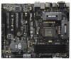
... USB 1.0/2.0/3.0 up to 5Gb/s - 4 x SATA2 3.0 Gb/s connectors, support RAID (RAID 0, RAID 1, RAID 10, RAID 5, Intel Rapid Storage and Intel Smart Response Technology), NCQ, AHCI and Hot Plug functions - 4 x SATA3 6.0Gb/s connectors - 1 x Floppy connector - 1 x IR header - 1 x CIR header - 1 x COM port header - 1 x HDMI_SPDIF header - 1 x IEEE 1394 header - 1 x Power LED header - ASRock Instant Boot English 8 ASRock Z68 Extreme4 Gen3 Motherboard...
... USB 1.0/2.0/3.0 up to 5Gb/s - 4 x SATA2 3.0 Gb/s connectors, support RAID (RAID 0, RAID 1, RAID 10, RAID 5, Intel Rapid Storage and Intel Smart Response Technology), NCQ, AHCI and Hot Plug functions - 4 x SATA3 6.0Gb/s connectors - 1 x Floppy connector - 1 x IR header - 1 x CIR header - 1 x COM port header - 1 x HDMI_SPDIF header - 1 x IEEE 1394 header - 1 x Power LED header - ASRock Instant Boot English 8 ASRock Z68 Extreme4 Gen3 Motherboard...

Quick Installation Guide
Page 9
... CAUTION 12) - CPU Frequency Stepless Control (see CAUTION 19) - Boot Failure Guard (B.F.G.) - Combo Cooler Option (C.C.O.) (see CAUTION 17) - Chassis Temperature Sensing - Microsoft® Windows® 7 / 7 64-bit / VistaTM / VistaTM 64-bit / XP / XP 64-bit compliant Certifications - English 9 ASRock Z68 Extreme4 Gen3 Motherboard - ASRock XFast USB (see CAUTION 18) - Voltage Monitoring: +12V, +5V, +3.3V, CPU...
... CAUTION 12) - CPU Frequency Stepless Control (see CAUTION 19) - Boot Failure Guard (B.F.G.) - Combo Cooler Option (C.C.O.) (see CAUTION 17) - Chassis Temperature Sensing - Microsoft® Windows® 7 / 7 64-bit / VistaTM / VistaTM 64-bit / XP / XP 64-bit compliant Certifications - English 9 ASRock Z68 Extreme4 Gen3 Motherboard - ASRock XFast USB (see CAUTION 18) - Voltage Monitoring: +12V, +5V, +3.3V, CPU...

Quick Installation Guide
Page 31
...Angle CIR Receiver is used for ASRock motherboard with most of ASRock motherboards. Find the CIR header located next to connect it before you boot the system. * ASRock Smart Remote is only supported by some of the chassis on ASRock motherboard. USB 2.0 header (9-pin, black) ...CIR header. 2.8 ASRock Smart Remote Installation Guide ASRock Smart Remote is only used for front USB only. Please refer to the USB_PWR USB 2.0 header (as below procedures for the motherboard support list: http://www.asrock.com 31 ASRock Z68 Extreme4 Gen3 Motherboard Connect the front USB cable to below ...
...Angle CIR Receiver is used for ASRock motherboard with most of ASRock motherboards. Find the CIR header located next to connect it before you boot the system. * ASRock Smart Remote is only supported by some of the chassis on ASRock motherboard. USB 2.0 header (9-pin, black) ...CIR header. 2.8 ASRock Smart Remote Installation Guide ASRock Smart Remote is only used for front USB only. Please refer to the USB_PWR USB 2.0 header (as below procedures for the motherboard support list: http://www.asrock.com 31 ASRock Z68 Extreme4 Gen3 Motherboard Connect the front USB cable to below ...

Quick Installation Guide
Page 43
...(South Bridge module specific) ACPI module initialization CSM initialization Reserved for future AMI DXE codes OEM DXE initialization codes Boot Device Selection (BDS) phase is started Driver connecting is started PCI Bus initialization is started PCI Bus Hot Plug Controller... devices connect Console input devices connect Super IO Initialization USB initialization is started USB Reset USB Detect USB Enable Reserved for future AMI codes IDE initialization is started IDE Reset IDE Detect IDE Enable SCSI initialization is started SCSI Reset English 43 ASRock Z68 Extreme4 Gen3 Motherboard
...(South Bridge module specific) ACPI module initialization CSM initialization Reserved for future AMI DXE codes OEM DXE initialization codes Boot Device Selection (BDS) phase is started Driver connecting is started PCI Bus initialization is started PCI Bus Hot Plug Controller... devices connect Console input devices connect Super IO Initialization USB initialization is started USB Reset USB Detect USB Enable Reserved for future AMI codes IDE initialization is started IDE Reset IDE Detect IDE Enable SCSI initialization is started SCSI Reset English 43 ASRock Z68 Extreme4 Gen3 Motherboard

Quick Installation Guide
Page 44
... Legacy Boot event Exit Boot Services event Runtime Set Virtual Address MAP Begin Runtime Set Virtual Address MAP End Legacy Option ROM Initialization System Reset USB hot plug PCI bus hot plug Clean-up of NVRAM Configuration Reset (reset of the Architectural Protocols ... Some of NVRAM settings) Reserved for Legacy Option ROM No Console Output Devices are found Invalid password Error loading Boot Option (LoadImage returned error) Boot Option is failed (StartImage returned error) Flash update is failed Reset protocol is not available English 44 ASRock Z68 Extreme4 Gen3 Motherboard
... Legacy Boot event Exit Boot Services event Runtime Set Virtual Address MAP Begin Runtime Set Virtual Address MAP End Legacy Option ROM Initialization System Reset USB hot plug PCI bus hot plug Clean-up of NVRAM Configuration Reset (reset of the Architectural Protocols ... Some of NVRAM settings) Reserved for Legacy Option ROM No Console Output Devices are found Invalid password Error loading Boot Option (LoadImage returned error) Boot Option is failed (StartImage returned error) Flash update is failed Reset protocol is not available English 44 ASRock Z68 Extreme4 Gen3 Motherboard


