
Intel Rapid Storage Guide
Page 12
... 3. Select the appropriate number of hard drives and press Space to select the drive. Switch the SATA Operation Mode option to enter the BIOS Setup program after the Power-On-Self-Test (POST) memory test begins. 2. When the Intel Rapid Storage Technology option ROM status screen ...a RAID volume (F6 install method) In order to install an operating system onto a RAID volume, the RAID option must be enabled in the system BIOS. 1. The F6 installation method is not required for Microsoft Windows 7 or Note Microsoft Windows 8. Click the Storage Configuration menu. 4. Unless you have ...
... 3. Select the appropriate number of hard drives and press Space to select the drive. Switch the SATA Operation Mode option to enter the BIOS Setup program after the Power-On-Self-Test (POST) memory test begins. 2. When the Intel Rapid Storage Technology option ROM status screen ...a RAID volume (F6 install method) In order to install an operating system onto a RAID volume, the RAID option must be enabled in the system BIOS. 1. The F6 installation method is not required for Microsoft Windows 7 or Note Microsoft Windows 8. Click the Storage Configuration menu. 4. Unless you have ...

RAID Installation Guide
Page 1
... a RAID array 8 2.4.1 Configuring a RAID array Using UEFI Setup Utility....... 9 2.4.2 Configuring a PCIE SSD RAID Array Using UEFI Setup Utility 13 2.4.3 Configuring a RAID array Using Intel RAID BIOS....... 18 3. Installing Windows® on a HDD larger than 2TB in RAID mode 22 4. Guide to SATA Hard Disks Installation 2 1.1 Serial ATA (SATA) Hard Disks Installation...
... a RAID array 8 2.4.1 Configuring a RAID array Using UEFI Setup Utility....... 9 2.4.2 Configuring a PCIE SSD RAID Array Using UEFI Setup Utility 13 2.4.3 Configuring a RAID array Using Intel RAID BIOS....... 18 3. Installing Windows® on a HDD larger than 2TB in RAID mode 22 4. Guide to SATA Hard Disks Installation 2 1.1 Serial ATA (SATA) Hard Disks Installation...

RAID Installation Guide
Page 6
... capacity and the other hard disk has 60GB, the maximum storage capacity for data protection (the new drive must be in RAID mode. * The system BIOS must be of the same size or larger than the existing drive). In the process you create RAID, the system will operate under a clean environment...
... capacity and the other hard disk has 60GB, the maximum storage capacity for data protection (the new drive must be in RAID mode. * The system BIOS must be of the same size or larger than the existing drive). In the process you create RAID, the system will operate under a clean environment...

RAID Installation Guide
Page 7
STEP 1: Setting the BIOS RAID Items After installing the hard disk drives, please set the necessary RAID items in UEFI setup. Press [Enter] to [...Windows® 10 64-bit / 8.1 64-bit / 8 64-bit / 7 / 7 64-bit OS on your system, and press key to enter BIOS setup utility. STEP 2: Use ASRock Easy RAID Installer Easy RAID Installer can copy the RAID driver from a support CD to your USB storage device with RAID functions, please...bit / 8.1 64-bit / 8 64-bit / 7 / 7 64-bit OS on your SATA / SATA2 / SATA3 HDDs with just one simple click in the BIOS before setting your RAID configuration.
STEP 1: Setting the BIOS RAID Items After installing the hard disk drives, please set the necessary RAID items in UEFI setup. Press [Enter] to [...Windows® 10 64-bit / 8.1 64-bit / 8 64-bit / 7 / 7 64-bit OS on your system, and press key to enter BIOS setup utility. STEP 2: Use ASRock Easy RAID Installer Easy RAID Installer can copy the RAID driver from a support CD to your USB storage device with RAID functions, please...bit / 8.1 64-bit / 8 64-bit / 7 / 7 64-bit OS on your SATA / SATA2 / SATA3 HDDs with just one simple click in the BIOS before setting your RAID configuration.

RAID Installation Guide
Page 8
... Option ROM Setting UEFI SETUP UTILITY\Boot\ CSM [Launch Storage n/a OpROM policy] = [UEFI only] Required RAID Utility UEFI Setup Utility Intel® RAID BIOS setup utility OS HDD Capacity Ultra Fast Boot Windows 10 / 8.1 / 8 Under 2.2 Over 2.2 TB TB Over 2.2 TB Enabled Enabled Disabled Under 2.2 ...n/a Setting Storage OpROM policy] = [UEFI only] Required UEFI Setup UEFI Setup UEFI Setup RAID Utility Utility Utility Utility Intel® RAID BIOS setup utility 8 2.4 Configuring a RAID array You can configure a RAID array using either UEFI Setup Utility or Intel® RAID...
... Option ROM Setting UEFI SETUP UTILITY\Boot\ CSM [Launch Storage n/a OpROM policy] = [UEFI only] Required RAID Utility UEFI Setup Utility Intel® RAID BIOS setup utility OS HDD Capacity Ultra Fast Boot Windows 10 / 8.1 / 8 Under 2.2 Over 2.2 TB TB Over 2.2 TB Enabled Enabled Disabled Under 2.2 ...n/a Setting Storage OpROM policy] = [UEFI only] Required UEFI Setup UEFI Setup UEFI Setup RAID Utility Utility Utility Utility Intel® RAID BIOS setup utility 8 2.4 Configuring a RAID array You can configure a RAID array using either UEFI Setup Utility or Intel® RAID...

RAID Installation Guide
Page 18
Press . In the Create Volume Menu, under Name item, please key-in a unique name with 1-16 letters for your computer. Volume0 18 Wait until you see the RAID software prompting you to press . Create RAID Volume window appears. Then, the Intel RAID Utility - 2.4.3 Configuring a RAID array Using Intel RAID BIOS Reboot your RAID volume then press .
Press . In the Create Volume Menu, under Name item, please key-in a unique name with 1-16 letters for your computer. Volume0 18 Wait until you see the RAID software prompting you to press . Create RAID Volume window appears. Then, the Intel RAID Utility - 2.4.3 Configuring a RAID array Using Intel RAID BIOS Reboot your RAID volume then press .

RAID Installation Guide
Page 21
After the completion, you will see the detailed information about the RAID that you want to configure RAID functions after you set up. If you are only allowed to create one RAID partition at a time under Windows environment to delete a RAID volume, please select the option Delete RAID Volume, press , and then follow the instructions on the screen. 21 If you want to complete the setup of RAID. Press to create an extra RAID partition, please use the RAID utility under BIOS RAID environment. Please note that you install OS.
After the completion, you will see the detailed information about the RAID that you want to configure RAID functions after you set up. If you are only allowed to create one RAID partition at a time under Windows environment to delete a RAID volume, please select the option Delete RAID Volume, press , and then follow the instructions on the screen. 21 If you want to complete the setup of RAID. Press to create an extra RAID partition, please use the RAID utility under BIOS RAID environment. Please note that you install OS.

RAID Installation Guide
Page 22
Installing Windows® on a HDD under 2TB in RAID mode After the UEFI and RAID BIOS setup you may start installing Windows® 10 64-bit / 8.1 64-bit / 8 64-bit / 7 / 7 64-bit OS as usual. 22 3.
Installing Windows® on a HDD under 2TB in RAID mode After the UEFI and RAID BIOS setup you may start installing Windows® 10 64-bit / 8.1 64-bit / 8 64-bit / 7 / 7 64-bit OS as usual. 22 3.

RAID Installation Guide
Page 23
... STEP 1: Copy Intel® RAID drivers into a USB flash disk You can download the drivers from ASRock's website and unzip the files into a USB flash disk or copy the files from ASRock's motherboard support CD. (Please copy the files under the following directory: 32 bit: ..\i386\Win7_Intel.. 64...-bit: ..\AMD64\Win7-64_Intel.. 4. Please make sure to boot. 23 After the UEFI and RAID BIOS setup, please follow the steps below. Installing...
... STEP 1: Copy Intel® RAID drivers into a USB flash disk You can download the drivers from ASRock's website and unzip the files into a USB flash disk or copy the files from ASRock's motherboard support CD. (Please copy the files under the following directory: 32 bit: ..\i386\Win7_Intel.. 64...-bit: ..\AMD64\Win7-64_Intel.. 4. Please make sure to boot. 23 After the UEFI and RAID BIOS setup, please follow the steps below. Installing...

User Manual
Page 5
3.1 Installing Drivers 37 3.2 A-Tuning 38 3.2.1 Installing A-Tuning 38 3.2.2 Using A-Tuning 38 3.3 ASRock Live Update & APP Shop 41 3.3.1 UI Overview 41 3.3.2 Apps 42 3.3.3 BIOS & Drivers 45 3.3.4 Setting 46 3.4 Enabling USB Ports for Windows® 7 Installation 47 3.5 ASRock AURA RGB LED 50 Chapter 4 UEFI SETUP UTILITY 51 4.1 Introduction 51 4.2 EZ Mode 52 4.3 Advanced Mode 53 4.3.1 UEFI...
3.1 Installing Drivers 37 3.2 A-Tuning 38 3.2.1 Installing A-Tuning 38 3.2.2 Using A-Tuning 38 3.3 ASRock Live Update & APP Shop 41 3.3.1 UI Overview 41 3.3.2 Apps 42 3.3.3 BIOS & Drivers 45 3.3.4 Setting 46 3.4 Enabling USB Ports for Windows® 7 Installation 47 3.5 ASRock AURA RGB LED 50 Chapter 4 UEFI SETUP UTILITY 51 4.1 Introduction 51 4.2 EZ Mode 52 4.3 Advanced Mode 53 4.3.1 UEFI...
User Manual
Page 7
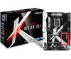
...; ASRock Z270 Killer SLI/ac / Z270 Killer SLI Quick Installation Guide • ASRock Z270 Killer SLI/ac / Z270 Killer SLI Support CD • 1 x I/O Panel Shield • 2 x Serial ATA (SATA) Data Cables (Optional) • 1 x ASRock SLI_HB_Bridge_2S Card (Optional) • 2 x Screws for M.2 Sockets (Optional) • 2 x ASRock WiFi 2.4/5 GHz Antennas (Optional) (for purchasing ASRock Z270 Killer SLI/ac / Z270 Killer SLI motherboard, a reliable motherboard produced under ASRock's consistently stringent quality control. Because the motherboard specifications and the BIOS...
...; ASRock Z270 Killer SLI/ac / Z270 Killer SLI Quick Installation Guide • ASRock Z270 Killer SLI/ac / Z270 Killer SLI Support CD • 1 x I/O Panel Shield • 2 x Serial ATA (SATA) Data Cables (Optional) • 1 x ASRock SLI_HB_Bridge_2S Card (Optional) • 2 x Screws for M.2 Sockets (Optional) • 2 x ASRock WiFi 2.4/5 GHz Antennas (Optional) (for purchasing ASRock Z270 Killer SLI/ac / Z270 Killer SLI motherboard, a reliable motherboard produced under ASRock's consistently stringent quality control. Because the motherboard specifications and the BIOS...
User Manual
Page 11
...) fan power. • 2 x Chassis Fan Connectors (4-pin) (Smart Fan Speed Con- Z270 Killer SLI/ac / Z270 Killer SLI ** Supports Intel® OptaneTM Technology ** Supports NVMe SSD as boot disks ** Supports ASRock U.2 Kit Connector • 1 x COM Port Header • 1 x TPM Header •...Headers (Support 5 USB 2.0 ports) (Supports ESD Protection (ASRock Full Spike Protection)) • 1 x USB 3.0 Header (Supports 2 USB 3.0 ports) (Supports ESD Protection (ASRock Full Spike Protection)) BIOS Feature • AMI UEFI Legal BIOS with multilingual GUI support • ACPI 6.0 Compliant wake up...
...) fan power. • 2 x Chassis Fan Connectors (4-pin) (Smart Fan Speed Con- Z270 Killer SLI/ac / Z270 Killer SLI ** Supports Intel® OptaneTM Technology ** Supports NVMe SSD as boot disks ** Supports ASRock U.2 Kit Connector • 1 x COM Port Header • 1 x TPM Header •...Headers (Support 5 USB 2.0 ports) (Supports ESD Protection (ASRock Full Spike Protection)) • 1 x USB 3.0 Header (Supports 2 USB 3.0 ports) (Supports ESD Protection (ASRock Full Spike Protection)) BIOS Feature • AMI UEFI Legal BIOS with multilingual GUI support • ACPI 6.0 Compliant wake up...

User Manual
Page 12
... disk with xHCI drivers packed into the ISO file is a certain risk involved with overclocking, including adjusting the setting in the BIOS, applying Untied Overclocking Technology, or using third-party overclocking tools. It should be done at your system. Please refer to the... BSMI • ErP/EuP ready (ErP/EuP ready power supply is required) * For detailed product information, please visit our website: http://www.asrock.com Please realize that there is required. English 6 Hardware Monitor • CPU / Chassis / Chassis Optional/Water Pump temperature sensing • CPU ...
... disk with xHCI drivers packed into the ISO file is a certain risk involved with overclocking, including adjusting the setting in the BIOS, applying Untied Overclocking Technology, or using third-party overclocking tools. It should be done at your system. Please refer to the... BSMI • ErP/EuP ready (ErP/EuP ready power supply is required) * For detailed product information, please visit our website: http://www.asrock.com Please realize that there is required. English 6 Hardware Monitor • CPU / Chassis / Chassis Optional/Water Pump temperature sensing • CPU ...

User Manual
Page 13
1.3 Motherboard Layout PS2 Keyboard /Mouse USB 3.0 T: USB1 B: USB2 HDMI1 M2_WIFI1* ATX12V1 Z270 Killer SLI/ac / Z270 Killer SLI CPU_FAN1 DDR4_A1 (64 bit, 288-pin module) DDR4_A2 (64 bit, 288-pin module) DDR4_B1 (64 bit, 288-pin module) DDR4_B2 (64 ... SPK Bottom: Optical SPDIF Top: Center: FRONT Bottom: MIC IN RoHS CHA_FAN2 USB3_5_6 M2_1 1 PCIE1 CT24 CT23 CT22 CT21 SATA_4_5 PCIE2 SATA_2_3 SATA_0_1 PCIE3 Intel Z270 PCIE4 T B1 1 PCIE5 T B2 1 Ultra M.2 PCIe Gen3 x4 CMOS Battery CT24 CT23 CT22 CT21 M2_2 PCIE6 HD_AUDIO1 1 COM1 1 TPMS1 1 CLRMOS1 1 RGB_LED1 1 ...
1.3 Motherboard Layout PS2 Keyboard /Mouse USB 3.0 T: USB1 B: USB2 HDMI1 M2_WIFI1* ATX12V1 Z270 Killer SLI/ac / Z270 Killer SLI CPU_FAN1 DDR4_A1 (64 bit, 288-pin module) DDR4_A2 (64 bit, 288-pin module) DDR4_B1 (64 bit, 288-pin module) DDR4_B2 (64 ... SPK Bottom: Optical SPDIF Top: Center: FRONT Bottom: MIC IN RoHS CHA_FAN2 USB3_5_6 M2_1 1 PCIE1 CT24 CT23 CT22 CT21 SATA_4_5 PCIE2 SATA_2_3 SATA_0_1 PCIE3 Intel Z270 PCIE4 T B1 1 PCIE5 T B2 1 Ultra M.2 PCIe Gen3 x4 CMOS Battery CT24 CT23 CT22 CT21 M2_2 PCIE6 HD_AUDIO1 1 COM1 1 TPMS1 1 CLRMOS1 1 RGB_LED1 1 ...

User Manual
Page 28
... pin2 and pin3 on the pins, the jumper is removed. Clear CMOS Jumper (CLRMOS1) (see p.7, No. 19) Default Clear CMOS CLRMOS1 allows you update the BIOS. English 22 If no jumper cap is placed on the pins, the jumper is placed on these 2 pins. When the jumper cap is placed on... clear the data in CMOS. However, please do the clear-CMOS action. If you need to clear the CMOS when you just finish updating the BIOS, you must boot up the system first, and then shut it down before you do not clear the CMOS right after you to default setup...
... pin2 and pin3 on the pins, the jumper is removed. Clear CMOS Jumper (CLRMOS1) (see p.7, No. 19) Default Clear CMOS CLRMOS1 allows you update the BIOS. English 22 If no jumper cap is placed on the pins, the jumper is placed on these 2 pins. When the jumper cap is placed on... clear the data in CMOS. However, please do the clear-CMOS action. If you need to clear the CMOS when you just finish updating the BIOS, you must boot up the system first, and then shut it down before you do not clear the CMOS right after you to default setup...

User Manual
Page 51
Step 3 Click Update to see more items you will see a list of recommended or critical updates for the BIOS or drivers. Z270 Killer SLI/ac / Z270 Killer SLI 3.3.3 BIOS & Drivers Installing BIOS or Drivers When the "BIOS & Drivers" tab is selected, you want to update. Click on Step 2 to start the update process. 45 English Step 1 Please check the item information before update. Click to select one or more details. Please update them all soon.
Step 3 Click Update to see more items you will see a list of recommended or critical updates for the BIOS or drivers. Z270 Killer SLI/ac / Z270 Killer SLI 3.3.3 BIOS & Drivers Installing BIOS or Drivers When the "BIOS & Drivers" tab is selected, you want to update. Click on Step 2 to start the update process. 45 English Step 1 Please check the item information before update. Click to select one or more details. Please update them all soon.

User Manual
Page 58
... of your system, such as CPU speed, DRAM frequency, SATA information, fan speed, etc. 4.2 EZ Mode The EZ Mode screen appears when you enter the BIOS setup program by default. EZ mode is a dashboard which contains multiple readings of the system's current status.
... of your system, such as CPU speed, DRAM frequency, SATA information, fan speed, etc. 4.2 EZ Mode The EZ Mode screen appears when you enter the BIOS setup program by default. EZ mode is a dashboard which contains multiple readings of the system's current status.

User Manual
Page 59
... screen. 4.3.1 UEFI Menu Bar The top of the screen has a menu bar with the following sections for the detailed configurations. Refer to configure the BIOS settings. Z270 Killer SLI/ac / Z270 Killer SLI 4.3 Advanced Mode The Advanced Mode provides more options to the following selections: Main For setting system time/date information OC Tweaker For overclocking configurations...
... screen. 4.3.1 UEFI Menu Bar The top of the screen has a menu bar with the following sections for the detailed configurations. Refer to configure the BIOS settings. Z270 Killer SLI/ac / Z270 Killer SLI 4.3 Advanced Mode The Advanced Mode provides more options to the following selections: Main For setting system time/date information OC Tweaker For overclocking configurations...

User Manual
Page 61
Favorite Display your collection of BIOS items. Press F5 to add/remove your favorite items. 55 English Z270 Killer SLI/ac / Z270 Killer SLI 4.4 Main Screen When you enter the UEFI SETUP UTILITY, the Main screen will appear and display the system overview.
Favorite Display your collection of BIOS items. Press F5 to add/remove your favorite items. 55 English Z270 Killer SLI/ac / Z270 Killer SLI 4.4 Main Screen When you enter the UEFI SETUP UTILITY, the Main screen will appear and display the system overview.

User Manual
Page 63
... same as the CPU Ratio. BCLK Frequency The CPU speed is a more stressful workload that the BIOS will increase the internal CPU clock speed but also affect the clock speed of other components. Z270 Killer SLI/ac / Z270 Killer SLI CPU Configuration Multi Core Enhancement Improve the system's performance by forcing the CPU to reduce power consumption...
... same as the CPU Ratio. BCLK Frequency The CPU speed is a more stressful workload that the BIOS will increase the internal CPU clock speed but also affect the clock speed of other components. Z270 Killer SLI/ac / Z270 Killer SLI CPU Configuration Multi Core Enhancement Improve the system's performance by forcing the CPU to reduce power consumption...


