
User Manual
Page 4
... and Quad SLITM Operation Guide 26 2.7.1 Installing Two SLITM-Ready Graphics Cards 26 2.7.2 Driver Installation and Setup 28 2.8 CrossFireXTM , 3-Way CrossFireXTM and Quad CrossFireXTM Operation Guide 29 2.8.1 Installing Two CrossFireXTM-Ready Graphics Cards 29 2.8.2 Installing Three CrossFireXTM-Ready Graphics Cards 31 2.8.3 Driver Installation and Setup 32 2.9 M.2 WiFi/BT Module Installation Guide 33 2.10 M.2_SSD (NGFF) Module...
... and Quad SLITM Operation Guide 26 2.7.1 Installing Two SLITM-Ready Graphics Cards 26 2.7.2 Driver Installation and Setup 28 2.8 CrossFireXTM , 3-Way CrossFireXTM and Quad CrossFireXTM Operation Guide 29 2.8.1 Installing Two CrossFireXTM-Ready Graphics Cards 29 2.8.2 Installing Three CrossFireXTM-Ready Graphics Cards 31 2.8.3 Driver Installation and Setup 32 2.9 M.2 WiFi/BT Module Installation Guide 33 2.10 M.2_SSD (NGFF) Module...
User Manual
Page 5
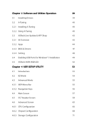
... Update & APP Shop 43 3.3.1 UI Overview 43 3.3.2 Apps 44 3.3.3 BIOS & Drivers 47 3.3.4 Setting 48 3.4 Enabling USB Ports for Windows® 7 Installation 49 3.5 ASRock AURA RGB LED 52 Chapter 4 UEFI SETUP UTILITY 53 4.1 Introduction 53 4.2 EZ Mode 54 4.3 Advanced Mode 55 4.3.1 UEFI Menu Bar 55 4.3.2 Navigation Keys 56 4.4 Main ...
... Update & APP Shop 43 3.3.1 UI Overview 43 3.3.2 Apps 44 3.3.3 BIOS & Drivers 47 3.3.4 Setting 48 3.4 Enabling USB Ports for Windows® 7 Installation 49 3.5 ASRock AURA RGB LED 52 Chapter 4 UEFI SETUP UTILITY 53 4.1 Introduction 53 4.2 EZ Mode 54 4.3 Advanced Mode 55 4.3.1 UEFI Menu Bar 55 4.3.2 Navigation Keys 56 4.4 Main ...
User Manual
Page 7
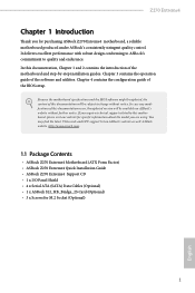
... introduction of the BIOS setup. ASRock website http://www.asrock.com. 1.1 Package Contents • ASRock Z270 Extreme4 Motherboard (ATX Form Factor) • ASRock Z270 Extreme4 Quick Installation Guide • ASRock Z270 Extreme4 Support CD • 1 x I/O Panel Shield • 4 x Serial ATA (SATA) Data Cables (Optional) • 1 x ASRock SLI_HB_Bridge_2S Card (Optional) • 3 x Screws for purchasing ASRock Z270 Extreme4 motherboard, a reliable motherboard produced under ASRock's consistently stringent quality control. If...
... introduction of the BIOS setup. ASRock website http://www.asrock.com. 1.1 Package Contents • ASRock Z270 Extreme4 Motherboard (ATX Form Factor) • ASRock Z270 Extreme4 Quick Installation Guide • ASRock Z270 Extreme4 Support CD • 1 x I/O Panel Shield • 4 x Serial ATA (SATA) Data Cables (Optional) • 1 x ASRock SLI_HB_Bridge_2S Card (Optional) • 3 x Screws for purchasing ASRock Z270 Extreme4 motherboard, a reliable motherboard produced under ASRock's consistently stringent quality control. If...
User Manual
Page 8
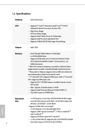
... design • Supports Intel® Turbo Boost 2.0 Technology • Supports Intel® K-Series unlocked CPUs • Supports ASRock BCLK Full-range Overclocking • Intel® Z270 Memory • Dual Channel DDR4 Memory Technology • 4 x DDR4 DIMM Slots • Supports DDR4 3866+(OC)*/3733(OC... * 3866+(OC) memory frequency can only be achieved when a single memory module is installed (Single channel memory). * Please refer to Memory Support List on ASRock's website for more information. (http://www.asrock.com/) ** 7th Gen Intel® CPU supports DDR4 up to 2400; 6th Gen...
... design • Supports Intel® Turbo Boost 2.0 Technology • Supports Intel® K-Series unlocked CPUs • Supports ASRock BCLK Full-range Overclocking • Intel® Z270 Memory • Dual Channel DDR4 Memory Technology • 4 x DDR4 DIMM Slots • Supports DDR4 3866+(OC)*/3733(OC... * 3866+(OC) memory frequency can only be achieved when a single memory module is installed (Single channel memory). * Please refer to Memory Support List on ASRock's website for more information. (http://www.asrock.com/) ** 7th Gen Intel® CPU supports DDR4 up to 2400; 6th Gen...

User Manual
Page 12
...(Support 6 USB 2.0 ports) (Intel® Z270) (Supports ESD Protection (ASRock Full Spike Protection)) • 1 x USB 3.0 Header (Supports 2 USB 3.0 ports) (Intel® Z270) (Supports ESD Protection (ASRock Full Spike Protection)) • 1 x USB ...3.0 Header (Supports 2 USB 3.0 ports) (ASMedia ASM1074 hub) (Supports ESD Protection (ASRock Full Spike Protection)) BIOS Feature • 2 x AMI UEFI Legal BIOS with xHCI drivers packed into the ISO file is required) 6 bit (For 6th Gen Intel® CPU) * To install...
...(Support 6 USB 2.0 ports) (Intel® Z270) (Supports ESD Protection (ASRock Full Spike Protection)) • 1 x USB 3.0 Header (Supports 2 USB 3.0 ports) (Intel® Z270) (Supports ESD Protection (ASRock Full Spike Protection)) • 1 x USB ...3.0 Header (Supports 2 USB 3.0 ports) (ASMedia ASM1074 hub) (Supports ESD Protection (ASRock Full Spike Protection)) BIOS Feature • 2 x AMI UEFI Legal BIOS with xHCI drivers packed into the ISO file is required) 6 bit (For 6th Gen Intel® CPU) * To install...
User Manual
Page 18
...or in the bag that the motherboard fits into it. Also remember to do not touch the ICs. • Whenever you install motherboard components or change any components, place them on a carpet. Failure to use a grounded wrist strap or touch a safety grounded object before...cord before you handle the components. • Hold components by the edges and do so may damage the motherboard. 12 English Before you install the motherboard, study the configuration of the following precautions before you uninstall any motherboard settings. • Make sure to the motherboard's components,...
...or in the bag that the motherboard fits into it. Also remember to do not touch the ICs. • Whenever you install motherboard components or change any components, place them on a carpet. Failure to use a grounded wrist strap or touch a safety grounded object before...cord before you handle the components. • Hold components by the edges and do so may damage the motherboard. 12 English Before you install the motherboard, study the configuration of the following precautions before you uninstall any motherboard settings. • Make sure to the motherboard's components,...

User Manual
Page 19
Otherwise, the CPU will be seriously damaged. 2. Do not force to insert the CPU into the socket, please check if the PnP cap is on the socket, if the CPU surface is found. Unplug all power cables before installing the CPU. 1 A B 2 13 English Z270 Extreme4 2.1 Installing the CPU 1. Before you insert the 1151-Pin CPU into the socket if above situation is unclean, or if there are any bent pins in the socket.
Otherwise, the CPU will be seriously damaged. 2. Do not force to insert the CPU into the socket, please check if the PnP cap is on the socket, if the CPU surface is found. Unplug all power cables before installing the CPU. 1 A B 2 13 English Z270 Extreme4 2.1 Installing the CPU 1. Before you insert the 1151-Pin CPU into the socket if above situation is unclean, or if there are any bent pins in the socket.

User Manual
Page 22
2.2 Installing the CPU Fan and Heatsink 1 2 CPU_FAN English 16
2.2 Installing the CPU Fan and Heatsink 1 2 CPU_FAN English 16

User Manual
Page 23
..., DDR2 or DDR3 memory module into the slot at incorrect orientation. It is unable to install identical (the same brand, speed, size and chip-type) DDR4 DIMM pairs. 2. Z270 Extreme4 2.3 Installing Memory Modules (DIMM) This motherboard provides four 288-pin DDR4 (Double Data Rate 4) DIMM slots, and supports Dual Channel Memory Technology. 1. It will...
..., DDR2 or DDR3 memory module into the slot at incorrect orientation. It is unable to install identical (the same brand, speed, size and chip-type) DDR4 DIMM pairs. 2. Z270 Extreme4 2.3 Installing Memory Modules (DIMM) This motherboard provides four 288-pin DDR4 (Double Data Rate 4) DIMM slots, and supports Dual Channel Memory Technology. 1. It will...
User Manual
Page 25
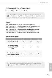
...card and make sure that the power supply is switched off or the power cord is used for the card before you start the installation. PCIe slots: PCIE1 (PCIe 3.0 x1 slot) is unplugged. PCIe Slot Configurations Single Graphics Card PCIE2 x16 PCIE4 N/A PCIE6 N/A...'s chassis fan connector (CHA_FAN1, CHA_FAN2 or CHA_FAN3 ) when using multiple graphics cards. 19 Before installing an expansion card, please make necessary hardware settings for PCI Express x1 lane width cards. Z270 Extreme4 2.4 Expansion Slots (PCI Express Slots) There are 6 PCI Express slots on the motherboard. PCIE3...
...card and make sure that the power supply is switched off or the power cord is used for the card before you start the installation. PCIe slots: PCIE1 (PCIe 3.0 x1 slot) is unplugged. PCIe Slot Configurations Single Graphics Card PCIE2 x16 PCIE4 N/A PCIE6 N/A...'s chassis fan connector (CHA_FAN1, CHA_FAN2 or CHA_FAN3 ) when using multiple graphics cards. 19 Before installing an expansion card, please make necessary hardware settings for PCI Express x1 lane width cards. Z270 Extreme4 2.4 Expansion Slots (PCI Express Slots) There are 6 PCI Express slots on the motherboard. PCIE3...
User Manual
Page 29
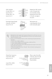
...Audio_L (LIN) to the front panel audio header by the steps below: A. If you use an AC'97 audio panel, please install it to OUT2_L. Connect Ground (GND) to MIC2_L. MIC_RET and OUT_RET are two headers on this motherboard. Front Panel Audio Header...Please connect fan cables to the fan connectors and match the black wire to the ground pin. FAN_SPEED_CONTROL 4 FAN_SPEED 3 FAN_VOLTAGE 2 GND 1 English 23 Z270 Extreme4 USB 3.0 Header (19-pin USB3_5_6) (see p.8, No. 9) (19-pin USB3_7_8) (see p.8, No. 7) Vbus IntA_PA_SSRXIntA_PA_SSRX+ GND IntA_PA_SSTXIntA_PA_SSTX+ GND ...
...Audio_L (LIN) to the front panel audio header by the steps below: A. If you use an AC'97 audio panel, please install it to OUT2_L. Connect Ground (GND) to MIC2_L. MIC_RET and OUT_RET are two headers on this motherboard. Front Panel Audio Header...Please connect fan cables to the fan connectors and match the black wire to the ground pin. FAN_SPEED_CONTROL 4 FAN_SPEED 3 FAN_VOLTAGE 2 GND 1 English 23 Z270 Extreme4 USB 3.0 Header (19-pin USB3_5_6) (see p.8, No. 9) (19-pin USB3_7_8) (see p.8, No. 7) Vbus IntA_PA_SSRXIntA_PA_SSRX+ GND IntA_PA_SSTXIntA_PA_SSTX+ GND ...
User Manual
Page 31
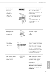
... 1 which allows users to choose from various LED lighting effects. Caution: Never install the RGB LED cable in card (AIC) to the Thunderbolt AIC connector via the GPIO cable. *Please install the Thunderbolt™ AIC card to PCIE6 (default slot). *Only one Thunderbolt ...wrong orientation; A TPM system also helps enhance network security, protects digital identities, and ensures platform integrity. otherwise, the cable may be damaged. 25 English Z270 Extreme4 Thunderbolt AIC Connectors (5-pin TB1) (see p.8, No. 23) (10-pin TB2) (see p.8, No. 17) RRXD1 DDTR#1 DDSR#1 CCTS#1 1 ...
... 1 which allows users to choose from various LED lighting effects. Caution: Never install the RGB LED cable in card (AIC) to the Thunderbolt AIC connector via the GPIO cable. *Please install the Thunderbolt™ AIC card to PCIE6 (default slot). *Only one Thunderbolt ...wrong orientation; A TPM system also helps enhance network security, protects digital identities, and ensures platform integrity. otherwise, the cable may be damaged. 25 English Z270 Extreme4 Thunderbolt AIC Connectors (5-pin TB1) (see p.8, No. 23) (10-pin TB2) (see p.8, No. 17) RRXD1 DDTR#1 DDSR#1 CCTS#1 1 ...

User Manual
Page 32
... to two identical PCI Express x16 graphics cards. Make sure that your system requires. Please refer to the NVIDIA® website for details. 2.7.1 Installing Two SLITM-Ready Graphics Cards Step 1 Insert one graphics card into PCIE2 slot and the other graphics card to the PCI Express graphics cards. 26... English Make sure that allows you to install up to use identical SLITM-ready graphics cards that are properly seated on the slots. Download the drivers from the NVIDIA® website: ...
... to two identical PCI Express x16 graphics cards. Make sure that your system requires. Please refer to the NVIDIA® website for details. 2.7.1 Installing Two SLITM-Ready Graphics Cards Step 1 Insert one graphics card into PCIE2 slot and the other graphics card to the PCI Express graphics cards. 26... English Make sure that allows you to install up to use identical SLITM-ready graphics cards that are properly seated on the slots. Download the drivers from the NVIDIA® website: ...

User Manual
Page 34
Please follow the below procedures to your system. Then select Maximize 3D performance and click Apply. 2.7.2 Driver Installation and Setup Install the graphics card drivers to enable the multi-GPU. Step 3 Reboot your system. Step 4 You can enable the Multi-Graphics Processing Unit (GPU) in the ...
Please follow the below procedures to your system. Then select Maximize 3D performance and click Apply. 2.7.2 Driver Installation and Setup Install the graphics card drivers to enable the multi-GPU. Step 3 Reboot your system. Step 4 You can enable the Multi-Graphics Processing Unit (GPU) in the ...
User Manual
Page 35
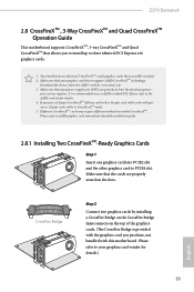
...-pipe cards while in CrossFireXTM mode. 5. CrossFire Bridge Step 2 Connect two graphics cards by installing a CrossFire Bridge on the CrossFire Bridge Interconnects on the slots. Z270 Extreme4 2.8 CrossFireXTM , 3-Way CrossFireXTM and Quad CrossFireXTM Operation Guide This motherboard supports CrossFireXTM, 3-way ... cards are AMD certified. 2. Please refer to PCIE4 slot. Please refer to AMD graphics card manuals for detailed installation guide. 2.8.1 Installing Two CrossFireXTM-Ready Graphics Cards Step 1 Insert one graphics card into PCIE2 slot and the other graphics card to ...
...-pipe cards while in CrossFireXTM mode. 5. CrossFire Bridge Step 2 Connect two graphics cards by installing a CrossFire Bridge on the CrossFire Bridge Interconnects on the slots. Z270 Extreme4 2.8 CrossFireXTM , 3-Way CrossFireXTM and Quad CrossFireXTM Operation Guide This motherboard supports CrossFireXTM, 3-way ... cards are AMD certified. 2. Please refer to PCIE4 slot. Please refer to AMD graphics card manuals for detailed installation guide. 2.8.1 Installing Two CrossFireXTM-Ready Graphics Cards Step 1 Insert one graphics card into PCIE2 slot and the other graphics card to ...
User Manual
Page 37
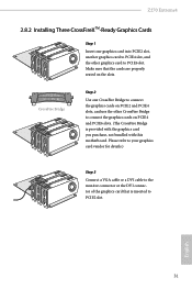
... of the graphics card that the cards are properly seated on PCIE4 and PCIE6 slots. (The CrossFire Bridge is inserted to PCIE2 slot. English 31 Z270 Extreme4 2.8.2 Installing Three CrossFireXTM-Ready Graphics Cards Step 1 Insert one CrossFire Bridge to connect the graphics cards on PCIE2 and PCIE4 slots, and use the other graphics...
... of the graphics card that the cards are properly seated on PCIE4 and PCIE6 slots. (The CrossFire Bridge is inserted to PCIE2 slot. English 31 Z270 Extreme4 2.8.2 Installing Three CrossFireXTM-Ready Graphics Cards Step 1 Insert one CrossFire Bridge to connect the graphics cards on PCIE2 and PCIE4 slots, and use the other graphics...

User Manual
Page 38
...details. Step 5 In the left pane, click Performance and then AMD CrossFireXTM. Then select Enable AMD CrossFireX and click Apply. Step 3 Install the required drivers and CATALYST Control Center then restart your computer and boot into OS. Please check AMD's website for AMD driver updates.... The Catalyst Uninstaller is an optional download. 2.8.3 Driver Installation and Setup Step 1 Power on your computer. AMD Catalyst Control Center Step 4 Double-click the AMD Catalyst Control Center icon in your...
...details. Step 5 In the left pane, click Performance and then AMD CrossFireXTM. Then select Enable AMD CrossFireX and click Apply. Step 3 Install the required drivers and CATALYST Control Center then restart your computer and boot into OS. Please check AMD's website for AMD driver updates.... The Catalyst Uninstaller is an optional download. 2.8.3 Driver Installation and Setup Step 1 Power on your computer. AMD Catalyst Control Center Step 4 Double-click the AMD Catalyst Control Center icon in your...
User Manual
Page 39
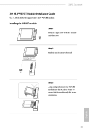
A A Step 3 Align and gently insert the WiFi/BT module into the M.2 slot. English 33 Please be used. Installing the WiFi/BT module Step 1 Prepare a type 2230 WiFi/BT module and the screw. Z270 Extreme4 2.9 M.2 WiFi/BT Module Installation Guide The M.2 Socket (Key E) supports type 2230 WiFi/BT module. Module Type: Type2230 PCB Length: 3cm Step 2 Find the nut location to be aware that the module only fits in one orientation.
A A Step 3 Align and gently insert the WiFi/BT module into the M.2 slot. English 33 Please be used. Installing the WiFi/BT module Step 1 Prepare a type 2230 WiFi/BT module and the screw. Z270 Extreme4 2.9 M.2 WiFi/BT Module Installation Guide The M.2 Socket (Key E) supports type 2230 WiFi/BT module. Module Type: Type2230 PCB Length: 3cm Step 2 Find the nut location to be aware that the module only fits in one orientation.
User Manual
Page 41
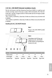
... and mSATA. Nut Location PCB Length Module Type 1 A 3cm Type2230 2 B 4.2cm Type 2242 3 C 6cm Type2260 4 D 8cm Type 2280 5 E 11cm Type 22110 English 35 Z270 Extreme4 2.10 M.2_SSD (NGFF) Module Installation Guide The M.2, also known as the Next Generation Form Factor (NGFF), is in use , the others will be used.... Installing the M.2_SSD (NGFF) Module Step 1 Prepare a M.2_SSD (NGFF) module and the screw. 5 4 3 2 1 Step 2 Depending on the PCB type and length of them is in ...
... and mSATA. Nut Location PCB Length Module Type 1 A 3cm Type2230 2 B 4.2cm Type 2242 3 C 6cm Type2260 4 D 8cm Type 2280 5 E 11cm Type 22110 English 35 Z270 Extreme4 2.10 M.2_SSD (NGFF) Module Installation Guide The M.2, also known as the Next Generation Form Factor (NGFF), is in use , the others will be used.... Installing the M.2_SSD (NGFF) Module Step 1 Prepare a M.2_SSD (NGFF) module and the screw. 5 4 3 2 1 Step 2 Depending on the PCB type and length of them is in ...
User Manual
Page 45
... CD To begin using the support CD, insert the CD into your computer. Drivers Menu The drivers compatible to display the menu. Z270 Extreme4 Chapter 3 Software and Utilities Operation 3.1 Installing Drivers The Support CD that comes with the motherboard contains necessary drivers and useful utilities that the motherboard supports. If the Main Menu...
... CD To begin using the support CD, insert the CD into your computer. Drivers Menu The drivers compatible to display the menu. Z270 Extreme4 Chapter 3 Software and Utilities Operation 3.1 Installing Drivers The Support CD that comes with the motherboard contains necessary drivers and useful utilities that the motherboard supports. If the Main Menu...


