RAID Installation Guide
Page 2
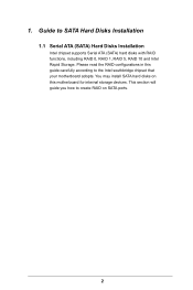
You may install SATA hard disks on SATA ports. 2 Guide to the Intel southbridge chipset that your motherboard adopts. Please read the RAID conigurations in this motherboard for internal storage devices. This section will guide you how to create RAID on this guide carefully according to SATA Hard Disks Installation 1.1 Serial ATA (SATA) Hard Disks Installation Intel chipset supports Serial ATA (SATA) hard disks with RAID functions, including RAID 0, RAID 1, RAID 5, RAID 10 and Intel Rapid Storage. 1.
You may install SATA hard disks on SATA ports. 2 Guide to the Intel southbridge chipset that your motherboard adopts. Please read the RAID conigurations in this motherboard for internal storage devices. This section will guide you how to create RAID on this guide carefully according to SATA Hard Disks Installation 1.1 Serial ATA (SATA) Hard Disks Installation Intel chipset supports Serial ATA (SATA) hard disks with RAID functions, including RAID 0, RAID 1, RAID 5, RAID 10 and Intel Rapid Storage. 1.
RAID Installation Guide
Page 3
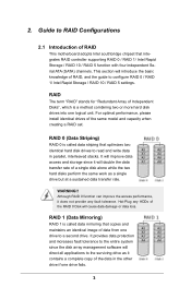
... data access and storage since the disk array management software will cause data damage or data loss. Guide to RAID Conigurations 2.1 Introduction of RAID This motherboard adopts Intel southbridge chipset that copies and maintains an identical image of RAID, and the guide to the surviving drive as a single drive but at...
... data access and storage since the disk array management software will cause data damage or data loss. Guide to RAID Conigurations 2.1 Introduction of RAID This motherboard adopts Intel southbridge chipset that copies and maintains an identical image of RAID, and the guide to the surviving drive as a single drive but at...
RAID Installation Guide
Page 18
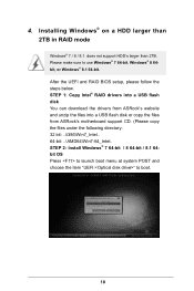
STEP 1: Copy Intel® RAID drivers into a USB lash disk You can download the drivers from ASRock's website and unzip the iles into a USB lash disk or copy the iles from ASRock's motherboard support CD. (Please copy the iles under the following directory: 32 bit: ..\i386\Win7_Intel.. 64-bit: ..\AMD64\Win7-64_Intel.. 4. After the...
STEP 1: Copy Intel® RAID drivers into a USB lash disk You can download the drivers from ASRock's website and unzip the iles into a USB lash disk or copy the iles from ASRock's motherboard support CD. (Please copy the iles under the following directory: 32 bit: ..\i386\Win7_Intel.. 64-bit: ..\AMD64\Win7-64_Intel.. 4. After the...
RAID Installation Guide
Page 20
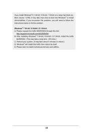
...; or install driver/utilities. Reboot your system. (It may take more time to reboot.) D. Windows® will need to follow the instructions below to install motherboard drivers and utilities. 20 E. Please request the hotix KB2505454 through this hotix then reboot by itself. Please start to ix this problem. Windows® 7 64...
...; or install driver/utilities. Reboot your system. (It may take more time to reboot.) D. Windows® will need to follow the instructions below to install motherboard drivers and utilities. 20 E. Please request the hotix KB2505454 through this hotix then reboot by itself. Please start to ix this problem. Windows® 7 64...

User Manual
Page 2
...in the documentation or product. "Perchlorate Material-special handling may cause undesired operation. Disclaimer: Speciications and information contained in this motherboard contains Perchlorate, a toxic substance controlled in advance. Operation is subject to the following two conditions: (1) this device may...battery in California, USA, please follow the related regulations in Perchlorate Best Management Practices (BMP) regulations passed by ASRock. Products and corporate names appearing in this documentation may or may be constructed as a commitment by the California ...
...in the documentation or product. "Perchlorate Material-special handling may cause undesired operation. Disclaimer: Speciications and information contained in this motherboard contains Perchlorate, a toxic substance controlled in advance. Operation is subject to the following two conditions: (1) this device may...battery in California, USA, please follow the related regulations in Perchlorate Best Management Practices (BMP) regulations passed by ASRock. Products and corporate names appearing in this documentation may or may be constructed as a commitment by the California ...

User Manual
Page 4
Contents Chapter 1 Introduction 1 1.1 Package Contents 1 1.2 Speciications 2 1.3 Motherboard Layout 6 1.4 I/O Panel 8 Chapter 2 Installation 10 2.1 Installing the CPU 11 2.2 Installing the CPU Fan and Heatsink 14 2.3 Installation of Memory Modules (DIMM) 15 2.4 Expansion Slots (PCI ...
Contents Chapter 1 Introduction 1 1.1 Package Contents 1 1.2 Speciications 2 1.3 Motherboard Layout 6 1.4 I/O Panel 8 Chapter 2 Installation 10 2.1 Installing the CPU 11 2.2 Installing the CPU Fan and Heatsink 14 2.3 Installation of Memory Modules (DIMM) 15 2.4 Expansion Slots (PCI ...
User Manual
Page 7
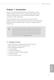
... for Ultra M.2 Socket 1 English ASRock website http://www.asrock.com. 1.1 Package Contents • ASRock X99M Extreme4 Motherboard (Micro ATX Form Factor) • ASRock X99M Extreme4 Quick Installation Guide • ASRock X99M Extreme4 Support CD • 1 x I/O Panel Shield • 1 x ASRock SLI_Bridge Card • 2 x Serial ATA (SATA) Data Cables (Optional) • 1 x HDD Saver Cable • 1 x Screw for purchasing ASRock X99M Extreme4 motherboard, a reliable motherboard produced under ASRock's consistently stringent quality control...
... for Ultra M.2 Socket 1 English ASRock website http://www.asrock.com. 1.1 Package Contents • ASRock X99M Extreme4 Motherboard (Micro ATX Form Factor) • ASRock X99M Extreme4 Quick Installation Guide • ASRock X99M Extreme4 Support CD • 1 x I/O Panel Shield • 1 x ASRock SLI_Bridge Card • 2 x Serial ATA (SATA) Data Cables (Optional) • 1 x HDD Saver Cable • 1 x Screw for purchasing ASRock X99M Extreme4 motherboard, a reliable motherboard produced under ASRock's consistently stringent quality control...

User Manual
Page 12
1.3 Motherboard Layout USB 2.0 T: USB1 B: USB2 PS2 Keyboard /Mouse CLRC BTN1 USB 2.0 T: USB3 B: USB4 ATX12V1 2011-3 Socket CPU_FAN1 CPU_FAN2 TPMS1 Dr. Debug 1 ATXPWR1 DDR4_D1 (64 bit, 284-... 128Mb BIOS BIOS_SEL1 A 1 SATA_PWR_1 B LAN BIOS_A BIOS_B BIOS_B_LED PCIE1 RoHS S_SATA3_2_3 M2_1 SATA3_0_3 CT5 Purity SoundTM 2 Ultra M.2 CT4 CT3 CT2 CT1 PCIe Gen3 x4 PCIE2 X99M Extreme4 Intel X99 SATA3_1_4 SATA3_2_5 HD_AUDIO1 1 PCIE_PWR1 PCIE3 TBT1 COM1 1 1 USB5_6 USB7_8 1 1 CHA_FAN1 SPEAKER1 1 CLRMOS1 1 PANEL1 PLED PWRBTN 1 HDLED RESET PLED1 1 1 English...
1.3 Motherboard Layout USB 2.0 T: USB1 B: USB2 PS2 Keyboard /Mouse CLRC BTN1 USB 2.0 T: USB3 B: USB4 ATX12V1 2011-3 Socket CPU_FAN1 CPU_FAN2 TPMS1 Dr. Debug 1 ATXPWR1 DDR4_D1 (64 bit, 284-... 128Mb BIOS BIOS_SEL1 A 1 SATA_PWR_1 B LAN BIOS_A BIOS_B BIOS_B_LED PCIE1 RoHS S_SATA3_2_3 M2_1 SATA3_0_3 CT5 Purity SoundTM 2 Ultra M.2 CT4 CT3 CT2 CT1 PCIe Gen3 x4 PCIE2 X99M Extreme4 Intel X99 SATA3_1_4 SATA3_2_5 HD_AUDIO1 1 PCIE_PWR1 PCIE3 TBT1 COM1 1 1 USB5_6 USB7_8 1 1 CHA_FAN1 SPEAKER1 1 CLRMOS1 1 PANEL1 PLED PWRBTN 1 HDLED RESET PLED1 1 1 English...

User Manual
Page 16
...damage from static electricity to use a grounded wrist strap or touch a safety grounded object before installing or removing the motherboard components. Before you uninstall any motherboard settings. • Make sure to unplug the power cord before you handle the components. • Hold components by ...the edges and do not touch the ICs. • Whenever you install the motherboard, study the coniguration of the following precautions before you install motherboard components or change any components, place them on a carpet. Failure to the chassis, please do so...
...damage from static electricity to use a grounded wrist strap or touch a safety grounded object before installing or removing the motherboard components. Before you uninstall any motherboard settings. • Make sure to unplug the power cord before you handle the components. • Hold components by ...the edges and do not touch the ICs. • Whenever you install the motherboard, study the coniguration of the following precautions before you install motherboard components or change any components, place them on a carpet. Failure to the chassis, please do so...

User Manual
Page 19
he cover must be placed if you wish to return the motherboard for ater service. 13 6 7 A B 8 X99M Extreme4 A B English Please save and replace the cover if the processor is removed.
he cover must be placed if you wish to return the motherboard for ater service. 13 6 7 A B 8 X99M Extreme4 A B English Please save and replace the cover if the processor is removed.

User Manual
Page 21
X99M Extreme4 2.3 Installation of Memory Modules (DIMM) his motherboard provides four 284-pin DDR4 (Double Data Rate 4) DIMM slots, and supports Quad Channel Memory Technology. 1. otherwise, this motherboard and DIMM may be damaged. 3. English 15 It is activated. he DIMM only its in the DDR4 DIMM slots, then ...allowed to install identical (the same brand, speed, size and chip-type) DDR4 DIMM pairs. 2. It will cause permanent damage to the motherboard and the DIMM if you always need to install a DDR, DDR2 or DDR3 memory module into the slot at incorrect orientation. Quad Channel ...
X99M Extreme4 2.3 Installation of Memory Modules (DIMM) his motherboard provides four 284-pin DDR4 (Double Data Rate 4) DIMM slots, and supports Quad Channel Memory Technology. 1. otherwise, this motherboard and DIMM may be damaged. 3. English 15 It is activated. he DIMM only its in the DDR4 DIMM slots, then ...allowed to install identical (the same brand, speed, size and chip-type) DDR4 DIMM pairs. 2. It will cause permanent damage to the motherboard and the DIMM if you always need to install a DDR, DDR2 or DDR3 memory module into the slot at incorrect orientation. Quad Channel ...

User Manual
Page 23
... card before you start the installation. PCIe slots: PCIE1 (PCIe 3.0 x16 slot) is unplugged. X99M Extreme4 2.4 Expansion Slots (PCI Express Slots) here are 3 PCI Express slots on the motherboard. PCIe Slot Conigurations (For CPU with 40 PCIe lanes) Single Graphics Card PCIE1 x16 PCIE2 N/A ...Two Graphics Cards in CrossFireXTM or SLITM Mode x16 x8 N/A For a better thermal environment, please connect a chassis fan to the motherboard's chassis fan connector (CHA_FAN1 or CHA_FAN2) when using multiple graphics cards. Please read the documentation of the expansion card and make sure...
... card before you start the installation. PCIe slots: PCIE1 (PCIe 3.0 x16 slot) is unplugged. X99M Extreme4 2.4 Expansion Slots (PCI Express Slots) here are 3 PCI Express slots on the motherboard. PCIe Slot Conigurations (For CPU with 40 PCIe lanes) Single Graphics Card PCIE1 x16 PCIE2 N/A ...Two Graphics Cards in CrossFireXTM or SLITM Mode x16 x8 N/A For a better thermal environment, please connect a chassis fan to the motherboard's chassis fan connector (CHA_FAN1 or CHA_FAN2) when using multiple graphics cards. Please read the documentation of the expansion card and make sure...

User Manual
Page 25
...switch and system status indicator on the chassis front panel. Note the positive and negative pins before connecting the cables. English 19 X99M Extreme4 2.6 Onboard Headers and Connectors Onboard headers and connectors are matched correctly. Press the reset switch to restart the computer if the computer...this header according to the power switch on the chassis front panel. he front panel design may conigure the way to the motherboard. Do NOT place jumper caps over the headers and connectors will cause permanent damage to turn of power switch, reset switch, ...
...switch and system status indicator on the chassis front panel. Note the positive and negative pins before connecting the cables. English 19 X99M Extreme4 2.6 Onboard Headers and Connectors Onboard headers and connectors are matched correctly. Press the reset switch to restart the computer if the computer...this header according to the power switch on the chassis front panel. he front panel design may conigure the way to the motherboard. Do NOT place jumper caps over the headers and connectors will cause permanent damage to turn of power switch, reset switch, ...

User Manual
Page 26
...p.6, No. 14) (SATA3_2_5: see p.6, No. 8) 20 USB_PWR PP+ GND DUMMY 1 GND P+ PUSB_PWR Besides four USB 2.0 ports on the I/O panel, there are two headers on this motherboard. Each USB 2.0 header can support two ports. English Vbus IntA_PA_SSRXIntA_PA_SSRX+ GND IntA_PA_SSTXIntA_PA_SSTX+ GND IntA_PA_DIntA_PA_D+ Vbus IntA_PB_SSRXIntA_PB_SSRX+ GND IntA_PB_SSTXIntA_PB_SSTX+ GND IntA_PB_DIntA_PB_D+ Dummy 1 Besides four USB 3.0 ports... S_SATA3_2 will not function. his USB 3.0 header can support two ports. If the eSATA port on the rear I /O panel, there is supported on this motherboard.
...p.6, No. 14) (SATA3_2_5: see p.6, No. 8) 20 USB_PWR PP+ GND DUMMY 1 GND P+ PUSB_PWR Besides four USB 2.0 ports on the I/O panel, there are two headers on this motherboard. Each USB 2.0 header can support two ports. English Vbus IntA_PA_SSRXIntA_PA_SSRX+ GND IntA_PA_SSTXIntA_PA_SSTX+ GND IntA_PA_DIntA_PA_D+ Vbus IntA_PB_SSRXIntA_PB_SSRX+ GND IntA_PB_SSTXIntA_PB_SSTX+ GND IntA_PB_DIntA_PB_D+ Dummy 1 Besides four USB 3.0 ports... S_SATA3_2 will not function. his USB 3.0 header can support two ports. If the eSATA port on the rear I /O panel, there is supported on this motherboard.

User Manual
Page 28
To use a 20-pin ATX power supply, please plug it along Pin 1 and Pin 5. his motherboard provides a 4-Pin CPU fan (Quiet Fan) connector. Please connect a 4 pin molex power cable to this connector to this connector when more than three graphics cards ... Saver Cable to manage the power state of HDD. Please connect a hunderboltTM add-in card (AIC) to Pin 1-3. 12 24 1 13 8 5 4 1 GND +12V DETECT 1 his motherboard provides a 24-pin ATX power connector. If you plan to connect a 3-Pin CPU fan, please connect it along Pin 1 and Pin 13. English CPU Fan...
To use a 20-pin ATX power supply, please plug it along Pin 1 and Pin 5. his motherboard provides a 4-Pin CPU fan (Quiet Fan) connector. Please connect a 4 pin molex power cable to this connector to this connector when more than three graphics cards ... Saver Cable to manage the power state of HDD. Please connect a hunderboltTM add-in card (AIC) to Pin 1-3. 12 24 1 13 8 5 4 1 GND +12V DETECT 1 his motherboard provides a 24-pin ATX power connector. If you plan to connect a 3-Pin CPU fan, please connect it along Pin 1 and Pin 13. English CPU Fan...

User Manual
Page 30
his motherboard has two BIOS chips, a primary BIOS (BIOS_A) and a backup BIOS (BIOS_B), which BIOS is corrupted or damaged, just lip the BIOS Selection Switch to quickly ... of the BIOS iles to the primary BIOS to clear the CMOS values or boot from either BIOS A or BIOS B. English 24 2.7 Smart Switches he motherboard has two smart switches: one Clear CMOS Switch and one BIOS Selection Switch, allowing users to ensure normal system operation. his function is workable only...
his motherboard has two BIOS chips, a primary BIOS (BIOS_A) and a backup BIOS (BIOS_B), which BIOS is corrupted or damaged, just lip the BIOS Selection Switch to quickly ... of the BIOS iles to the primary BIOS to clear the CMOS values or boot from either BIOS A or BIOS B. English 24 2.7 Smart Switches he motherboard has two smart switches: one Clear CMOS Switch and one BIOS Selection Switch, allowing users to ensure normal system operation. his function is workable only...

User Manual
Page 33
... other graphics card to the PCI Express graphics cards. 27 English It is recommended to two identical PCI Express x16 graphics cards. X99M Extreme4 2.9 SLITM and Quad SLITM Operation Guide his motherboard supports NVIDIA® SLITM and Quad SLITM (Scalable Link Interface) technology that allows you to install up to use identical SLITM...
... other graphics card to the PCI Express graphics cards. 27 English It is recommended to two identical PCI Express x16 graphics cards. X99M Extreme4 2.9 SLITM and Quad SLITM Operation Guide his motherboard supports NVIDIA® SLITM and Quad SLITM (Scalable Link Interface) technology that allows you to install up to use identical SLITM...

User Manual
Page 36
... to install up to the AMD's website for details.) English 30 Make sure that allows you purchase, not bundled with this motherboard. 2.10 CrossFireXTM and Quad CrossFireXTM Operation Guide his motherboard supports CrossFireXTM and Quad CrossFireXTM that your graphics card driver supports AMD CrossFireXTM technology. Please refer to AMD graphics card manuals...
... to install up to the AMD's website for details.) English 30 Make sure that allows you purchase, not bundled with this motherboard. 2.10 CrossFireXTM and Quad CrossFireXTM Operation Guide his motherboard supports CrossFireXTM and Quad CrossFireXTM that your graphics card driver supports AMD CrossFireXTM technology. Please refer to AMD graphics card manuals...

User Manual
Page 40
.... Please be used. Otherwise, release the standof by default. Step 5 Align and gently insert the M.2 (NGFF) SSD module into the desired nut location on the motherboard. Hand tighten the standof into the M.2 slot.
.... Please be used. Otherwise, release the standof by default. Step 5 Align and gently insert the M.2 (NGFF) SSD module into the desired nut location on the motherboard. Hand tighten the standof into the M.2 slot.

User Manual
Page 42
... end to the HDD Saver Connector (SATA_ PWR_1) placed near the SATA ports. For the sotware coniguration, please refer to the section 3.2 "A-Tuning" in this motherboard allows you to a SATA port on and off the connected HDDs via sotware when needed. Connect one end of the SATA data cable to switch...
... end to the HDD Saver Connector (SATA_ PWR_1) placed near the SATA ports. For the sotware coniguration, please refer to the section 3.2 "A-Tuning" in this motherboard allows you to a SATA port on and off the connected HDDs via sotware when needed. Connect one end of the SATA data cable to switch...

