
Quick Installation Guide
Page 3
... Power (EIRP) 18.5 + / -1.5 dbm 21.5 + / -1.5 dbm 18.5 + / -1.5 dbm (no TPC) 21.5 + / -1.5 dbm (TPC) 25.5 + / -1.5 dbm (no TPC) 28.5 + / -1.5 dbm (TPC) 8.5 + / -1.5 dbm This equipment should be installed and operated with directive 2014/53/EU issued by the Commision of the European Community. CE Warning This device complies with minimum distance 20cm between...
... Power (EIRP) 18.5 + / -1.5 dbm 21.5 + / -1.5 dbm 18.5 + / -1.5 dbm (no TPC) 21.5 + / -1.5 dbm (TPC) 25.5 + / -1.5 dbm (no TPC) 28.5 + / -1.5 dbm (TPC) 8.5 + / -1.5 dbm This equipment should be installed and operated with directive 2014/53/EU issued by the Commision of the European Community. CE Warning This device complies with minimum distance 20cm between...
Quick Installation Guide
Page 9
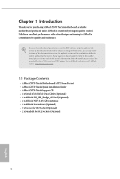
... quality and endurance. ASRock website http://www.asrock.com. 1.1 Package Contents • ASRock X570 Taichi Motherboard (ATX Form Factor) • ASRock X570 Taichi Quick Installation Guide • ASRock X570 Taichi Support CD • 4 x Serial ATA (SATA) Data Cables (Optional) • 1 x ASRock SLI_HB_Bridge_2S Card (Optional) • 2 x ASRock WiFi 2.4/5 GHz Antennas • 1 x ASRock Screwdriver (Optional) • 3 x Screws for M.2 Socket (Optional) • 2 x Standoffs for purchasing ASRock X570 Taichi motherboard, a reliable motherboard...
... quality and endurance. ASRock website http://www.asrock.com. 1.1 Package Contents • ASRock X570 Taichi Motherboard (ATX Form Factor) • ASRock X570 Taichi Quick Installation Guide • ASRock X570 Taichi Support CD • 4 x Serial ATA (SATA) Data Cables (Optional) • 1 x ASRock SLI_HB_Bridge_2S Card (Optional) • 2 x ASRock WiFi 2.4/5 GHz Antennas • 1 x ASRock Screwdriver (Optional) • 3 x Screws for M.2 Socket (Optional) • 2 x Standoffs for purchasing ASRock X570 Taichi motherboard, a reliable motherboard...

Quick Installation Guide
Page 11
...; DirectX 12, Pixel Shader 5.0 • Shared memory default 2GB. Max Shared memory supports up to 16GB. * The Max shared memory 16GB requires 32GB system memory installed. • Supports HDMI 2.0 with the package. resolution up to 4K x 2K (4096x2160) @ 60Hz • Supports Auto Lip Sync, Deep Color (12bpc), xvYCC and HBR (High...
...; DirectX 12, Pixel Shader 5.0 • Shared memory default 2GB. Max Shared memory supports up to 16GB. * The Max shared memory 16GB requires 32GB system memory installed. • Supports HDMI 2.0 with the package. resolution up to 4K x 2K (4096x2160) @ 60Hz • Supports Auto Lip Sync, Deep Color (12bpc), xvYCC and HBR (High...
Quick Installation Guide
Page 16
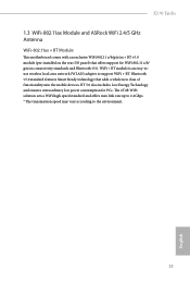
...-touse wireless local area network (WLAN) adapter to the environment. 13 English X570 Taichi 1.3 WiFi-802.11ax Module and ASRock WiFi 2.4/5 GHz Antenna WiFi-802.11ax + BT Module This motherboard comes with an exclusive WiFi 802.11 a/b/g/n/ax + BT v5.0 module (pre-installed on the rear I/O panel) that adds a whole new class of functionality...
...-touse wireless local area network (WLAN) adapter to the environment. 13 English X570 Taichi 1.3 WiFi-802.11ax Module and ASRock WiFi 2.4/5 GHz Antenna WiFi-802.11ax + BT Module This motherboard comes with an exclusive WiFi 802.11 a/b/g/n/ax + BT v5.0 module (pre-installed on the rear I/O panel) that adds a whole new class of functionality...

Quick Installation Guide
Page 17
... to secure the motherboard to the chassis, please do not overtighten the screws! Failure to unplug the power cord before installing or removing the motherboard. Pre-installation Precautions Take note of your motherboard directly on a grounded anti-static pad or in the bag that the motherboard fits ...into it. Also remember to you install the motherboard, study the configuration of the following precautions before you handle the components. • Hold components by the edges and do ...
... to secure the motherboard to the chassis, please do not overtighten the screws! Failure to unplug the power cord before installing or removing the motherboard. Pre-installation Precautions Take note of your motherboard directly on a grounded anti-static pad or in the bag that the motherboard fits ...into it. Also remember to you install the motherboard, study the configuration of the following precautions before you handle the components. • Hold components by the edges and do ...

Quick Installation Guide
Page 18
2.1 Installing the CPU Unplug all power cables before installing the CPU. 1 X570 Taichi 2 English 15
2.1 Installing the CPU Unplug all power cables before installing the CPU. 1 X570 Taichi 2 English 15
Quick Installation Guide
Page 20
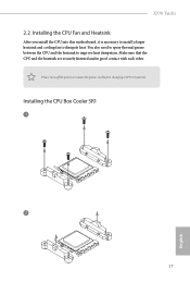
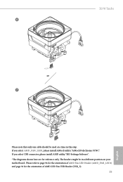
Installing the CPU Box Cooler SR1 1 2 17 English X570 Taichi 2.2 Installing the CPU Fan and Heatsink After you install the CPU into this motherboard, it is necessary to install a larger heatsink and cooling fan to improve heat dissipation. Please turn off the power or remove the power cord before changing a CPU or heatsink. Make sure that the CPU and the heatsink are securely fastened and in good contact with each other. You also need to spray thermal grease between the CPU and the heatsink to dissipate heat.
Installing the CPU Box Cooler SR1 1 2 17 English X570 Taichi 2.2 Installing the CPU Fan and Heatsink After you install the CPU into this motherboard, it is necessary to install a larger heatsink and cooling fan to improve heat dissipation. Please turn off the power or remove the power cord before changing a CPU or heatsink. Make sure that the CPU and the heatsink are securely fastened and in good contact with each other. You also need to spray thermal grease between the CPU and the heatsink to dissipate heat.

Quick Installation Guide
Page 22
Installing the AM4 Box Cooler SR2 1 X570 Taichi 2 English 19
Installing the AM4 Box Cooler SR2 1 X570 Taichi 2 English 19

Quick Installation Guide
Page 25
Installing the AM4 Box Cooler SR3 1 2 22 English
Installing the AM4 Box Cooler SR3 1 2 22 English
Quick Installation Guide
Page 28
If you select AMD_FAN_LED1, please install ASRock utility "ASRock Polychrome SYNC". Please refer to page 36 for the orientation of AMD Fan LED Header (AMD_FAN_LED1) and page 32 for reference only. X570 Taichi 6 CPU_FAN1 +12V RGB_LED2 or 7 CPU_FAN1 AMD_FAN_LED1 USB_5 Please note that only one cable should be in this step. The headers might be used...
If you select AMD_FAN_LED1, please install ASRock utility "ASRock Polychrome SYNC". Please refer to page 36 for the orientation of AMD Fan LED Header (AMD_FAN_LED1) and page 32 for reference only. X570 Taichi 6 CPU_FAN1 +12V RGB_LED2 or 7 CPU_FAN1 AMD_FAN_LED1 USB_5 Please note that only one cable should be in this step. The headers might be used...

Quick Installation Guide
Page 29
... SR 2933 SR/DR DR SR/DR DR 2667 SR/DR SR/DR SR/DR SR/DR 2133-2400 26 English It is unable to install a DDR, DDR2 or DDR3 memory module into a DDR4 slot; SR - - 3200 - SR - SR 3200 - AMD non-XMP Memory Frequency Support Ryzen Series... CPUs (Matisse): UDIMM Memory Slot A1 A2 B1 B2 Frequency (Mhz) - DR - 2.3 Installing Memory Modules (DIMM) This motherboard provides four 288-pin DDR4 (Double Data Rate 4) DIMM slots, and supports Dual Channel Memory Technology. 1. For dual channel configuration...
... SR 2933 SR/DR DR SR/DR DR 2667 SR/DR SR/DR SR/DR SR/DR 2133-2400 26 English It is unable to install a DDR, DDR2 or DDR3 memory module into a DDR4 slot; SR - - 3200 - SR - SR 3200 - AMD non-XMP Memory Frequency Support Ryzen Series... CPUs (Matisse): UDIMM Memory Slot A1 A2 B1 B2 Frequency (Mhz) - DR - 2.3 Installing Memory Modules (DIMM) This motherboard provides four 288-pin DDR4 (Double Data Rate 4) DIMM slots, and supports Dual Channel Memory Technology. 1. For dual channel configuration...

Quick Installation Guide
Page 32
... expansion card, please make necessary hardware settings for the card before you start the installation. PCIe Slot Configurations Ryzen Series CPUs (Matisse) Ryzen Series CPUs (Pinnacle Ridge) PCIE1 Gen4x8 Gen3x8 PCIE3 Gen4x8 Gen3x8 PCIE5 Gen4x4 Gen4x4 Gen3x8 N/A N/A Ryzen...(PCIe 4.0 x16 slot) is occupied, M2_3 will be disabled. English 29 PCIE4 (PCIe 4.0 x1 slot) is used for PCI Express x1 lane width cards. X570 Taichi 2.4 Expansion Slots (PCI Express Slots) There are 5 PCI Express slots on the motherboard. PCIE2 (PCIe 4.0 x1 slot) is used for PCI Express x1 lane ...
... expansion card, please make necessary hardware settings for the card before you start the installation. PCIe Slot Configurations Ryzen Series CPUs (Matisse) Ryzen Series CPUs (Pinnacle Ridge) PCIE1 Gen4x8 Gen3x8 PCIE3 Gen4x8 Gen3x8 PCIE5 Gen4x4 Gen4x4 Gen3x8 N/A N/A Ryzen...(PCIe 4.0 x16 slot) is occupied, M2_3 will be disabled. English 29 PCIE4 (PCIe 4.0 x1 slot) is used for PCI Express x1 lane width cards. X570 Taichi 2.4 Expansion Slots (PCI Express Slots) There are 5 PCI Express slots on the motherboard. PCIE2 (PCIe 4.0 x1 slot) is used for PCI Express x1 lane ...
Quick Installation Guide
Page 36
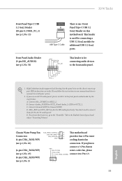
X570 Taichi Front Panel Type C USB 3.2 Gen2 Header (20-pin F_USB31_TC_1) (see p.1, No. 13) USB Type-C Cable There is used for connecting a USB 3.2 Gen2 module for additional USB 3.2 Gen2 ports. This header is one Front Panel Type C USB 3.2 Gen2 Header on the chassis must support HDA to install ...your system. 2. B. If you use an AC'97 audio panel, please install it to Ground (GND). Connect Ground (GND) to Pin 1-3. 1 2 34 33 High Definition Audio supports...
X570 Taichi Front Panel Type C USB 3.2 Gen2 Header (20-pin F_USB31_TC_1) (see p.1, No. 13) USB Type-C Cable There is used for connecting a USB 3.2 Gen2 module for additional USB 3.2 Gen2 ports. This header is one Front Panel Type C USB 3.2 Gen2 Header on the chassis must support HDA to install ...your system. 2. B. If you use an AC'97 audio panel, please install it to Ground (GND). Connect Ground (GND) to Pin 1-3. 1 2 34 33 High Definition Audio supports...
Quick Installation Guide
Page 38
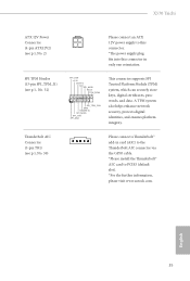
X570 Taichi ATX 12V Power Connector (4-pin ATX12V2) (see p.1, No. 2) Please connect an ATX 12V power supply to PCIE5 (default slot). *For the further information, please visit www.asrock.com. A TPM system also helps enhance network security, protects digital identities, and ensures ...platform integrity. SPI TPM Header (13-pin SPI_TPM_J1) (see p.1, No. 30) Please connect a Thunderbolt™ add-in card (AIC) to the 1 Thunderbolt AIC connector via the GPIO cable. *Please install...
X570 Taichi ATX 12V Power Connector (4-pin ATX12V2) (see p.1, No. 2) Please connect an ATX 12V power supply to PCIE5 (default slot). *For the further information, please visit www.asrock.com. A TPM system also helps enhance network security, protects digital identities, and ensures ...platform integrity. SPI TPM Header (13-pin SPI_TPM_J1) (see p.1, No. 30) Please connect a Thunderbolt™ add-in card (AIC) to the 1 Thunderbolt AIC connector via the GPIO cable. *Please install...

Quick Installation Guide
Page 39
... LED extension cable which allows users to choose from various LED lighting effects. Caution: Never install the Addressable LED cable in the wrong orientation; Caution: Never install the FAN LED cable in the wrong orientation; Caution: Never install the RGB LED cable in the wrong orientation; otherwise, the cable may be damaged. *Please...
... LED extension cable which allows users to choose from various LED lighting effects. Caution: Never install the Addressable LED cable in the wrong orientation; Caution: Never install the FAN LED cable in the wrong orientation; Caution: Never install the RGB LED cable in the wrong orientation; otherwise, the cable may be damaged. *Please...

Quick Installation Guide
Page 48
...M.2 Socket (M2_1) supports SATA3 6.0 Gb/s module and M.2 PCI Express module up to replace mPCIe and mSATA. C B A No. X570 Taichi 2.9 M.2_SSD (NGFF) Module Installation Guide (M2_1) The M.2, also known as the Next Generation Form Factor (NGFF), is a small size and versatile card edge connector that ...aims to Gen4x4 (64 Gb/s) (with Raven Ridge and Pinnacle Ridge) or Gen3 x2 (16 Gb/s). Installing the M.2_SSD (NGFF) Module Step 1 Prepare a M.2_SSD (NGFF) module and the screw. 3 2 1 Step 2 Depending on the PCB type and length ...
...M.2 Socket (M2_1) supports SATA3 6.0 Gb/s module and M.2 PCI Express module up to replace mPCIe and mSATA. C B A No. X570 Taichi 2.9 M.2_SSD (NGFF) Module Installation Guide (M2_1) The M.2, also known as the Next Generation Form Factor (NGFF), is a small size and versatile card edge connector that ...aims to Gen4x4 (64 Gb/s) (with Raven Ridge and Pinnacle Ridge) or Gen3 x2 (16 Gb/s). Installing the M.2_SSD (NGFF) Module Step 1 Prepare a M.2_SSD (NGFF) module and the screw. 3 2 1 Step 2 Depending on the PCB type and length ...

Quick Installation Guide
Page 49
... the motherboard. English Align and gently insert the M.2 (NGFF) SSD module into the desired nut location on the bottom side of the M.2 heatsink before you install a M.2 SSD module. Then hand tighten the standoff into the M.2 slot. C B A C B A 20o C NUT2 NUT1 46 Step 4 Prepare the M.2 standoff that the M.2 (NGFF) SSD... orientation. Step 5 Tighten the screw with the package. Please do not overtighten the screw as this might damage the module. 2 1 1 1 Step 3 1 Before installing a M.2 (NGFF) SSD module, please loosen the screws to secure the module into place.
... the motherboard. English Align and gently insert the M.2 (NGFF) SSD module into the desired nut location on the bottom side of the M.2 heatsink before you install a M.2 SSD module. Then hand tighten the standoff into the M.2 slot. C B A C B A 20o C NUT2 NUT1 46 Step 4 Prepare the M.2 standoff that the M.2 (NGFF) SSD... orientation. Step 5 Tighten the screw with the package. Please do not overtighten the screw as this might damage the module. 2 1 1 1 Step 3 1 Before installing a M.2 (NGFF) SSD module, please loosen the screws to secure the module into place.

Quick Installation Guide
Page 51
... and versatile card edge connector that aims to Gen4x4 (64 Gb/s). The Hyper M.2 Socket (M2_2) supports M.2 PCI Express module up to replace mPCIe and mSATA. Installing the M.2_SSD (NGFF) Module Step 1 This motherboard supports M.2_SSD (NGFF) module type 2260 and 2280 only. Step 2 Depending on the PCB type and length of...
... and versatile card edge connector that aims to Gen4x4 (64 Gb/s). The Hyper M.2 Socket (M2_2) supports M.2 PCI Express module up to replace mPCIe and mSATA. Installing the M.2_SSD (NGFF) Module Step 1 This motherboard supports M.2_SSD (NGFF) module type 2260 and 2280 only. Step 2 Depending on the PCB type and length of...

Quick Installation Guide
Page 52
... module only fits in one orientation. Then hand tighten the standoff into place. Align and gently insert the M.2 (NGFF) SSD module into the M.2 slot. 2 1 1 1 X570 Taichi 1 Step 3 Before installing a M.2 (NGFF) SSD module, please loosen the screws to secure the module into the desired nut location on the bottom side of the M.2 heatsink before...
... module only fits in one orientation. Then hand tighten the standoff into place. Align and gently insert the M.2 (NGFF) SSD module into the M.2 slot. 2 1 1 1 X570 Taichi 1 Step 3 Before installing a M.2 (NGFF) SSD module, please loosen the screws to secure the module into the desired nut location on the bottom side of the M.2 heatsink before...

Quick Installation Guide
Page 54
... (M2_3) supports M.2 SATA3 6.0 Gb/s module and M.2 PCI Express module up to replace mPCIe and mSATA. E D C B A No. X570 Taichi 2.11 M.2_SSD (NGFF) Module Installation Guide (M2_3) The M.2, also known as the Next Generation Form Factor (NGFF), is a small size and versatile card edge connector that aims to... Gen4x4 (64 Gb/s). * If M2_3 is occupied, PCIE5 slot will be used. Installing the M.2_SSD (NGFF) Module Step 1 Prepare a M.2_SSD (NGFF) module and the screw. 5 4 3 2 1 Step 2 Depending on the PCB type and ...
... (M2_3) supports M.2 SATA3 6.0 Gb/s module and M.2 PCI Express module up to replace mPCIe and mSATA. E D C B A No. X570 Taichi 2.11 M.2_SSD (NGFF) Module Installation Guide (M2_3) The M.2, also known as the Next Generation Form Factor (NGFF), is a small size and versatile card edge connector that aims to... Gen4x4 (64 Gb/s). * If M2_3 is occupied, PCIE5 slot will be used. Installing the M.2_SSD (NGFF) Module Step 1 Prepare a M.2_SSD (NGFF) module and the screw. 5 4 3 2 1 Step 2 Depending on the PCB type and ...


