User Manual
Page 5
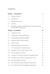
Contents Chapter 1 Introduction 1 1.1 Package Contents 1 1.2 Specifications 2 1.3 Motherboard Layout 7 1.4 I/O Panel 9 1.5 WiFi-802.11ac Module and ASRock WiFi 2.4/5 GHz Antennas (for X470 Master SLI/ac only) 12 Chapter 2 Installation 14 2.1 Installing the CPU 15 2.2 Installing the CPU Fan and Heatsink 17 2.3 Installing Memory Modules (DIMM) 26 2.4 Expansion Slots (PCI Express ...
Contents Chapter 1 Introduction 1 1.1 Package Contents 1 1.2 Specifications 2 1.3 Motherboard Layout 7 1.4 I/O Panel 9 1.5 WiFi-802.11ac Module and ASRock WiFi 2.4/5 GHz Antennas (for X470 Master SLI/ac only) 12 Chapter 2 Installation 14 2.1 Installing the CPU 15 2.2 Installing the CPU Fan and Heatsink 17 2.3 Installing Memory Modules (DIMM) 26 2.4 Expansion Slots (PCI Express ...
User Manual
Page 8
... endurance. ASRock website http://www.asrock.com. 1.1 Package Contents • ASRock X470 Master SLI/ac / X470 Master SLI Motherboard (ATX Form Factor) • ASRock X470 Master SLI/ac / X470 Master SLI Quick Installation Guide • ASRock X470 Master SLI/ac / X470 Master SLI Support CD • 1 x I/O Panel Shield • 2 x Serial ATA (SATA) Data Cables (Optional) • 1 x ASRock SLI_HB_Bridge_2S Card (Optional) • 2 x Screws for M.2 Sockets (Optional) • 2 x ASRock WiFi 2.4/5 GHz Antennas (Optional) (for purchasing ASRock X470 Master SLI/ac / X470 Master SLI motherboard...
... endurance. ASRock website http://www.asrock.com. 1.1 Package Contents • ASRock X470 Master SLI/ac / X470 Master SLI Motherboard (ATX Form Factor) • ASRock X470 Master SLI/ac / X470 Master SLI Quick Installation Guide • ASRock X470 Master SLI/ac / X470 Master SLI Support CD • 1 x I/O Panel Shield • 2 x Serial ATA (SATA) Data Cables (Optional) • 1 x ASRock SLI_HB_Bridge_2S Card (Optional) • 2 x Screws for M.2 Sockets (Optional) • 2 x ASRock WiFi 2.4/5 GHz Antennas (Optional) (for purchasing ASRock X470 Master SLI/ac / X470 Master SLI motherboard...

User Manual
Page 10
...ESD Protection • Supports Energy Efficient Ethernet 802.3az • Supports PXE Wireless LAN (for X470 Master SLI/ac only) • Intel® 802.11ac WiFi Module • Supports IEEE 802.11a/b/g/n/ac • Supports Dual-Band (2.4/5 GHz) • Supports high speed wireless connections up to 4K...with HDMI Port • Supports 4K Ultra HD (UHD) playback with HDMI Port Audio • 7.1 CH HD Audio with max. X470 Master SLI/ac / X470 Master SLI • Supports AMD Quad CrossFireXTM and CrossFireXTM • Supports NVIDIA® Quad SLITM and SLITM • 15μ Gold Contact...
...ESD Protection • Supports Energy Efficient Ethernet 802.3az • Supports PXE Wireless LAN (for X470 Master SLI/ac only) • Intel® 802.11ac WiFi Module • Supports IEEE 802.11a/b/g/n/ac • Supports Dual-Band (2.4/5 GHz) • Supports high speed wireless connections up to 4K...with HDMI Port • Supports 4K Ultra HD (UHD) playback with HDMI Port Audio • 7.1 CH HD Audio with max. X470 Master SLI/ac / X470 Master SLI • Supports AMD Quad CrossFireXTM and CrossFireXTM • Supports NVIDIA® Quad SLITM and SLITM • 15μ Gold Contact...
User Manual
Page 11
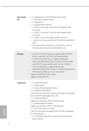
Rear Panel I/O • 2 x Antenna Ports (for X470 Master SLI/ac only) • 1 x PS/2 Mouse/Keyboard Port • 1 x HDMI Port • 1 x Optical SPDIF Out Port • 1 x USB 3.1 Gen2 Type-A Port (10 Gb/s) (Supports ESD Protection) • 1 x ... type 2230/2242/2260/2280 M.2 SATA3 6.0 Gb/s module and M.2 PCI Express module up to Gen2 x2 (10 Gb/s)* * Supports NVMe SSD as boot disks * Supports ASRock U.2 Kit Connector • 1 x COM Port Header • 1 x TPM Header • 1 x Power LED and Speaker Header • 1 x AMD Fan LED Header * The AMD Fan LED Header...
Rear Panel I/O • 2 x Antenna Ports (for X470 Master SLI/ac only) • 1 x PS/2 Mouse/Keyboard Port • 1 x HDMI Port • 1 x Optical SPDIF Out Port • 1 x USB 3.1 Gen2 Type-A Port (10 Gb/s) (Supports ESD Protection) • 1 x ... type 2230/2242/2260/2280 M.2 SATA3 6.0 Gb/s module and M.2 PCI Express module up to Gen2 x2 (10 Gb/s)* * Supports NVMe SSD as boot disks * Supports ASRock U.2 Kit Connector • 1 x COM Port Header • 1 x TPM Header • 1 x Power LED and Speaker Header • 1 x AMD Fan LED Header * The AMD Fan LED Header...
User Manual
Page 12
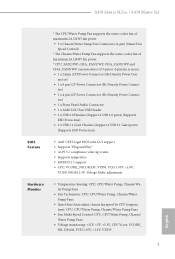
... Control: CPU, CPU/Water Pump, Chassis/ Water Pump Fans • Voltage monitoring: +12V, +5V, +3.3V, CPU Vcore, VCORE_ NB, DRAM, PCH 1.05V, +1.8V, VDDP 5 English X470 Master SLI/ac / X470 Master SLI * The CPU/Water Pump Fan supports the water cooler fan of maximum 2A (24W) fan power. • 3 x Chassis/Water Pump Fan Connectors (4-pin) (Smart Fan...
... Control: CPU, CPU/Water Pump, Chassis/ Water Pump Fans • Voltage monitoring: +12V, +5V, +3.3V, CPU Vcore, VCORE_ NB, DRAM, PCH 1.05V, +1.8V, VDDP 5 English X470 Master SLI/ac / X470 Master SLI * The CPU/Water Pump Fan supports the water cooler fan of maximum 2A (24W) fan power. • 3 x Chassis/Water Pump Fan Connectors (4-pin) (Smart Fan...

User Manual
Page 14
1.3 Motherboard Layout X470 Master SLI/ac / X470 Master SLI M2_WIFI_1* ATX12V1 ATX12V2 CPU_FAN2/WP CPU_FAN1 PS2 Keyboard/ Mouse HDMI1 ATXPWR1 DDR4_B2 (64 bit, 288-pin module) DDR4_B1 (64 bit, 288-pin module) DDR4_A2 (64 ...
1.3 Motherboard Layout X470 Master SLI/ac / X470 Master SLI M2_WIFI_1* ATX12V1 ATX12V2 CPU_FAN2/WP CPU_FAN1 PS2 Keyboard/ Mouse HDMI1 ATXPWR1 DDR4_B2 (64 bit, 288-pin module) DDR4_B1 (64 bit, 288-pin module) DDR4_A2 (64 ...

User Manual
Page 18
X470 Master SLI/ac / X470 Master SLI * There are two LEDs on each LAN port. Audio Output Channels 2 4 6 8 Front Speaker (No. 6) V V V V Rear Speaker (No. 4) -V V V Central / Bass (No. 3) --V V Line In (No. 5) ---V English 11 ...
X470 Master SLI/ac / X470 Master SLI * There are two LEDs on each LAN port. Audio Output Channels 2 4 6 8 Front Speaker (No. 6) V V V V Rear Speaker (No. 4) -V V V Central / Bass (No. 3) --V V Line In (No. 5) ---V English 11 ...

User Manual
Page 19
... Low Energy Technology and ensures extraordinary low power consumption for WiFi 802.11 a/b/ g/n/ac connectivity standards and Bluetooth v4.2. 1.5 WiFi-802.11ac Module and ASRock WiFi 2.4/5 GHz Antennas (for X470 Master SLI/ac only) WiFi-802.11ac + BT Module This motherboard comes with an exclusive WiFi 802....11 a/b/g/n/ac + BT v4.2 module (pre-installed on the rear I/O panel) that adds a whole...
... Low Energy Technology and ensures extraordinary low power consumption for WiFi 802.11 a/b/ g/n/ac connectivity standards and Bluetooth v4.2. 1.5 WiFi-802.11ac Module and ASRock WiFi 2.4/5 GHz Antennas (for X470 Master SLI/ac only) WiFi-802.11ac + BT Module This motherboard comes with an exclusive WiFi 802....11 a/b/g/n/ac + BT v4.2 module (pre-installed on the rear I/O panel) that adds a whole...

User Manual
Page 20
Turn the antenna clockwise until it is securely connected. Step 2 Connect the two WiFi 2.4/5 GHz Antennas to adjust the direction of the antenna for a stronger signal. 13 English Step 3 Set the WiFi 2.4/5 GHz Antenna as shown in the illustration. *You may need to the antenna connectors. X470 Master SLI/ac / X470 Master SLI WiFi Antennas Installation Guide Step 1 Prepare the WiFi 2.4/5 GHz Antennas that come with the package.
Turn the antenna clockwise until it is securely connected. Step 2 Connect the two WiFi 2.4/5 GHz Antennas to adjust the direction of the antenna for a stronger signal. 13 English Step 3 Set the WiFi 2.4/5 GHz Antenna as shown in the illustration. *You may need to the antenna connectors. X470 Master SLI/ac / X470 Master SLI WiFi Antennas Installation Guide Step 1 Prepare the WiFi 2.4/5 GHz Antennas that come with the package.

User Manual
Page 22
2.1 Installing the CPU X470 Master SLI/ac / X470 Master SLI Unplug all power cables before installing the CPU. 1 2 English 15
2.1 Installing the CPU X470 Master SLI/ac / X470 Master SLI Unplug all power cables before installing the CPU. 1 2 English 15

User Manual
Page 24
Installing the CPU Box Cooler SR1 1 2 17 English Please turn off the power or remove the power cord before changing a CPU or heatsink. You also need to spray thermal grease between the CPU and the heatsink to dissipate heat. Make sure that the CPU and the heatsink are securely fastened and in good contact with each other. X470 Master SLI/ac / X470 Master SLI 2.2 Installing the CPU Fan and Heatsink After you install the CPU into this motherboard, it is necessary to install a larger heatsink and cooling fan to improve heat dissipation.
Installing the CPU Box Cooler SR1 1 2 17 English Please turn off the power or remove the power cord before changing a CPU or heatsink. You also need to spray thermal grease between the CPU and the heatsink to dissipate heat. Make sure that the CPU and the heatsink are securely fastened and in good contact with each other. X470 Master SLI/ac / X470 Master SLI 2.2 Installing the CPU Fan and Heatsink After you install the CPU into this motherboard, it is necessary to install a larger heatsink and cooling fan to improve heat dissipation.

User Manual
Page 26
X470 Master SLI/ac / X470 Master SLI Installing the AM4 Box Cooler SR2 1 2 19 English
X470 Master SLI/ac / X470 Master SLI Installing the AM4 Box Cooler SR2 1 2 19 English

User Manual
Page 28
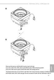
Please refer to page 35 for reference only. X470 Master SLI/ac / X470 Master SLI 4 CPU_FAN1 5 RGB LED Cable 4-pin FAN cable CPU_FAN1 +12V AMD_FAN_LED1 *The diagram shown here are for the orientation of AMD Fan LED Header (AMD_FAN_LED1). 21 English
Please refer to page 35 for reference only. X470 Master SLI/ac / X470 Master SLI 4 CPU_FAN1 5 RGB LED Cable 4-pin FAN cable CPU_FAN1 +12V AMD_FAN_LED1 *The diagram shown here are for the orientation of AMD Fan LED Header (AMD_FAN_LED1). 21 English
User Manual
Page 32
X470 Master SLI/ac / X470 Master SLI 6 CPU_FAN1 +12V AMD_FAN_LED1 or 7 CPU_FAN1 AMD_FAN_LED1 USB_5 Please note that only one cable should be used at a time in this step. If you select USB connector, please install AMD utility "SR3 Settings Software". *The diagram shown here are for the orientation of AMD LED Fan USB Header (USB_5). 25 English Please refer to page 35 for the orientation of AMD Fan LED Header (AMD_FAN_LED1) and page 32 for reference only. If you select AMD_FAN_LED1, please install ASRock utility "ASRock Polychrome RGB".
X470 Master SLI/ac / X470 Master SLI 6 CPU_FAN1 +12V AMD_FAN_LED1 or 7 CPU_FAN1 AMD_FAN_LED1 USB_5 Please note that only one cable should be used at a time in this step. If you select USB connector, please install AMD utility "SR3 Settings Software". *The diagram shown here are for the orientation of AMD LED Fan USB Header (USB_5). 25 English Please refer to page 35 for the orientation of AMD Fan LED Header (AMD_FAN_LED1) and page 32 for reference only. If you select AMD_FAN_LED1, please install ASRock utility "ASRock Polychrome RGB".
User Manual
Page 36
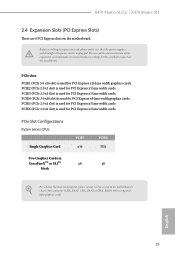
... for PCI Express x1 lane width cards. PCIe slots: PCIE1 (PCIe 3.0 x16 slot) is used for PCI Express x8 lane width graphics cards. English 29 X470 Master SLI/ac / X470 Master SLI 2.4 Expansion Slots (PCI Express Slots) There are 6 PCI Express slots on the motherboard. PCIE4 (PCIe 3.0 x16 slot) is used for PCI Express x16 lane width...
... for PCI Express x1 lane width cards. PCIe slots: PCIE1 (PCIe 3.0 x16 slot) is used for PCI Express x8 lane width graphics cards. English 29 X470 Master SLI/ac / X470 Master SLI 2.4 Expansion Slots (PCI Express Slots) There are 6 PCI Express slots on the motherboard. PCIE4 (PCIe 3.0 x16 slot) is used for PCI Express x16 lane width...

User Manual
Page 38
.... 16) PLED+ PLEDPWRBTN# GND 1 GND RESET# GND HDLEDHDLED+ Connect the power switch, reset switch and system status indicator on the chassis to turn off (S5). X470 Master SLI/ac / X470 Master SLI 2.6 Onboard Headers and Connectors Onboard headers and connectors are matched correctly. HDLED (Hard Drive Activity LED): Connect to perform a normal restart.
.... 16) PLED+ PLEDPWRBTN# GND 1 GND RESET# GND HDLEDHDLED+ Connect the power switch, reset switch and system status indicator on the chassis to turn off (S5). X470 Master SLI/ac / X470 Master SLI 2.6 Onboard Headers and Connectors Onboard headers and connectors are matched correctly. HDLED (Hard Drive Activity LED): Connect to perform a normal restart.

User Manual
Page 40
X470 Master SLI/ac / X470 Master SLI Front Panel Audio Header (9-pin HD_AUDIO1) (see p.7, No. 21) GND FAN_VOLTAGE_CONTROL FAN_SPEED FAN_SPEED_CONTROL 4 3 2 1 FAN_SPEED_CONTROL CHA_FAN_SPEED FAN_VOLTAGE GND This motherboard provides three 4-Pin water cooling chassis ...FAN_SPEED_CONTROL vides a 4-Pin CPU fan (Quiet Fan) connector. If you plan to connect a 3-Pin CPU fan, please connect it to Pin 1-3. B. If you use an AC'97 audio panel, please install it to Pin 1-3. 33 English Chassis /Water Pump Fan Connectors (4-pin CHA_FAN1/WP) (see p.7, No. 12) (4-pin CHA_FAN2/WP) (see...
X470 Master SLI/ac / X470 Master SLI Front Panel Audio Header (9-pin HD_AUDIO1) (see p.7, No. 21) GND FAN_VOLTAGE_CONTROL FAN_SPEED FAN_SPEED_CONTROL 4 3 2 1 FAN_SPEED_CONTROL CHA_FAN_SPEED FAN_VOLTAGE GND This motherboard provides three 4-Pin water cooling chassis ...FAN_SPEED_CONTROL vides a 4-Pin CPU fan (Quiet Fan) connector. If you plan to connect a 3-Pin CPU fan, please connect it to Pin 1-3. B. If you use an AC'97 audio panel, please install it to Pin 1-3. 33 English Chassis /Water Pump Fan Connectors (4-pin CHA_FAN1/WP) (see p.7, No. 12) (4-pin CHA_FAN2/WP) (see...

User Manual
Page 42
..., the cable may be damaged. This header is used to connect RGB LED extension cable which can securely store keys, digital certificates, passwords, and data. X470 Master SLI/ac / X470 Master SLI TPM Header (17-pin TPMS1) (see p.7, No. 25) 1 AMD FAN LED Header (4-pin AMD_FAN_ LED1) (see p.7, No. 11) 1 12V G R B RGB LED Header (4-pin RGB_LED1) (see...
..., the cable may be damaged. This header is used to connect RGB LED extension cable which can securely store keys, digital certificates, passwords, and data. X470 Master SLI/ac / X470 Master SLI TPM Header (17-pin TPMS1) (see p.7, No. 25) 1 AMD FAN LED Header (4-pin AMD_FAN_ LED1) (see p.7, No. 11) 1 12V G R B RGB LED Header (4-pin RGB_LED1) (see...

User Manual
Page 44
... PCI Express x16 graphics cards. You should only use a NVIDIA® certified PSU. Step 2 If required, connect the auxiliary power source to PCIE4 slot. Requirements 1. X470 Master SLI/ac / X470 Master SLI 2.7 SLITM and Quad SLITM Operation Guide This motherboard supports NVIDIA® SLITM and Quad SLITM (Scalable Link Interface) technology that the cards are NVIDIA®...
... PCI Express x16 graphics cards. You should only use a NVIDIA® certified PSU. Step 2 If required, connect the auxiliary power source to PCIE4 slot. Requirements 1. X470 Master SLI/ac / X470 Master SLI 2.7 SLITM and Quad SLITM Operation Guide This motherboard supports NVIDIA® SLITM and Quad SLITM (Scalable Link Interface) technology that the cards are NVIDIA®...

User Manual
Page 46
...Quad SLITM mode Step 1 Double-click the NVIDIA Control Panel icon in the NVIDIA® nView system tray utility. Step 3 Reboot your system. X470 Master SLI/ac / X470 Master SLI 2.7.2 Driver Installation and Setup Install the graphics card drivers to enable the multi-GPU. Please follow the below procedures to your system. Then select ... 4 You can enable the Multi-Graphics Processing Unit (GPU) in the Windows® system tray. Step 2 In the left pane, click Set SLI and PhysX configuration. After that, you can freely enjoy the benefits of SLITM or Quad SLITM. 39 English
...Quad SLITM mode Step 1 Double-click the NVIDIA Control Panel icon in the NVIDIA® nView system tray utility. Step 3 Reboot your system. X470 Master SLI/ac / X470 Master SLI 2.7.2 Driver Installation and Setup Install the graphics card drivers to enable the multi-GPU. Please follow the below procedures to your system. Then select ... 4 You can enable the Multi-Graphics Processing Unit (GPU) in the Windows® system tray. Step 2 In the left pane, click Set SLI and PhysX configuration. After that, you can freely enjoy the benefits of SLITM or Quad SLITM. 39 English

