
User Manual
Page 2
...be constructed as a commitment by the California Legislature. All rights reserved. Copyright Notice: No part of this documentation, ASRock does not provide warranty of any kind, either expressed or implied, including but not limited to infringe. With respect to...see www.dtsc.ca.gov/hazardouswaste/ perchlorate" ASRock Website: http://www.asrock.com Products and corporate names appearing in Perchlorate Best Management Practices (BMP) regulations passed by ASRock. Disclaimer: Specifications and information contained in this motherboard contains Perchlorate, a toxic substance controlled in ...
...be constructed as a commitment by the California Legislature. All rights reserved. Copyright Notice: No part of this documentation, ASRock does not provide warranty of any kind, either expressed or implied, including but not limited to infringe. With respect to...see www.dtsc.ca.gov/hazardouswaste/ perchlorate" ASRock Website: http://www.asrock.com Products and corporate names appearing in Perchlorate Best Management Practices (BMP) regulations passed by ASRock. Disclaimer: Specifications and information contained in this motherboard contains Perchlorate, a toxic substance controlled in ...
User Manual
Page 4
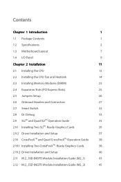
Contents Chapter 1 Introduction 1 1.1 Package Contents 1 1.2 Specifications 2 1.3 Motherboard Layout 7 1.4 I/O Panel 9 Chapter 2 Installation 11 2.1 Installing the CPU 12 2.2 Installing the CPU Fan and Heatsink 14 2.3 Installing Memory Modules (DIMM) 23 2.4 Expansion Slots (PCI Express ...
Contents Chapter 1 Introduction 1 1.1 Package Contents 1 1.2 Specifications 2 1.3 Motherboard Layout 7 1.4 I/O Panel 9 Chapter 2 Installation 11 2.1 Installing the CPU 12 2.2 Installing the CPU Fan and Heatsink 14 2.3 Installing Memory Modules (DIMM) 23 2.4 Expansion Slots (PCI Express ...
User Manual
Page 7
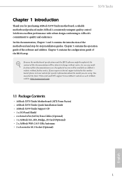
... to quality and endurance. ASRock website http://www.asrock.com. 1.1 Package Contents • ASRock X370 Taichi Motherboard (ATX Form Factor) • ASRock X370 Taichi Quick Installation Guide • ASRock X370 Taichi Support CD • 1 x I/O Panel Shield • 4 x Serial ATA (SATA) Data Cables (Optional) • 1 x ASRock SLI_HB_Bridge_2S Card (Optional) • 2 x ASRock WiFi 2.4/5 GHz Antennas • 2 x Screws for purchasing ASRock X370 Taichi motherboard, a reliable motherboard produced under ASRock's consistently stringent quality control...
... to quality and endurance. ASRock website http://www.asrock.com. 1.1 Package Contents • ASRock X370 Taichi Motherboard (ATX Form Factor) • ASRock X370 Taichi Quick Installation Guide • ASRock X370 Taichi Support CD • 1 x I/O Panel Shield • 4 x Serial ATA (SATA) Data Cables (Optional) • 1 x ASRock SLI_HB_Bridge_2S Card (Optional) • 2 x ASRock WiFi 2.4/5 GHz Antennas • 2 x Screws for purchasing ASRock X370 Taichi motherboard, a reliable motherboard produced under ASRock's consistently stringent quality control...
User Manual
Page 13
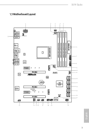
1.3 Motherboard Layout X370 Taichi 1 26 PS2 Keyboard /Mouse USB 3.0 T: USB1 B: USB2 CLRC BTN1 M2_WIFI_1 ATX12V1 CHA_FAN3/W_PUMP 2 3 45 CPU_FAN1 CPU_OPT/W_PUMP ATXPWR1 DDR4_A1 (64 bit, 288-pin ... BIOS ROM Ultra M.2 PCIe Gen3 x4 1 8 USB3_7_8 1 9 10 CHA_FAN1 11 12 SATA3_1_2 SATA3_3_4 Purity SoundTM 4 HD_AUDIO1 1 CMOS Battery PCIE3 PCIE4 X370 Ta i c h i PCIE5 RGB_LED2 1 RGB_LED1 1 CHA_FAN2 SPK_PLED1 1 AMD Promontory X370 M2_2 USB_3_4 USB_1_2 1 1 RoHS CLRMOS1 1 Dr. Debug SATA3_A1_A2 SATA3_7_8 SATA3_5_6 PLED PWRBTN 1 HDLED RESET PANEL1 13 14 15 16 17 25...
1.3 Motherboard Layout X370 Taichi 1 26 PS2 Keyboard /Mouse USB 3.0 T: USB1 B: USB2 CLRC BTN1 M2_WIFI_1 ATX12V1 CHA_FAN3/W_PUMP 2 3 45 CPU_FAN1 CPU_OPT/W_PUMP ATXPWR1 DDR4_A1 (64 bit, 288-pin ... BIOS ROM Ultra M.2 PCIe Gen3 x4 1 8 USB3_7_8 1 9 10 CHA_FAN1 11 12 SATA3_1_2 SATA3_3_4 Purity SoundTM 4 HD_AUDIO1 1 CMOS Battery PCIE3 PCIE4 X370 Ta i c h i PCIE5 RGB_LED2 1 RGB_LED1 1 CHA_FAN2 SPK_PLED1 1 AMD Promontory X370 M2_2 USB_3_4 USB_1_2 1 1 RoHS CLRMOS1 1 Dr. Debug SATA3_A1_A2 SATA3_7_8 SATA3_5_6 PLED PWRBTN 1 HDLED RESET PANEL1 13 14 15 16 17 25...

User Manual
Page 17
... to you uninstall any components, place them on a carpet. Before you install the motherboard, study the configuration of the following precautions before you install motherboard components or change any motherboard settings. • Make sure to unplug the power cord before you handle the components... do not touch the ICs. • Whenever you and damages to motherboard components. • In order to avoid damage from static electricity to the motherboard's components, NEVER place your chassis to do not overtighten the screws! X370 Taichi Chapter 2 Installation This is a ATX form factor...
... to you uninstall any components, place them on a carpet. Before you install the motherboard, study the configuration of the following precautions before you install motherboard components or change any motherboard settings. • Make sure to unplug the power cord before you handle the components... do not touch the ICs. • Whenever you and damages to motherboard components. • In order to avoid damage from static electricity to the motherboard's components, NEVER place your chassis to do not overtighten the screws! X370 Taichi Chapter 2 Installation This is a ATX form factor...

User Manual
Page 20
You also need to spray thermal grease between the CPU and the heatsink to dissipate heat. Make sure that the CPU and the heatsink are securely fastened and in good contact with each other. Please turn off the power or remove the power cord before changing a CPU or heatsink. Installing the CPU Box Cooler SR1 1 2 14 English 2.2 Installing the CPU Fan and Heatsink After you install the CPU into this motherboard, it is necessary to install a larger heatsink and cooling fan to improve heat dissipation.
You also need to spray thermal grease between the CPU and the heatsink to dissipate heat. Make sure that the CPU and the heatsink are securely fastened and in good contact with each other. Please turn off the power or remove the power cord before changing a CPU or heatsink. Installing the CPU Box Cooler SR1 1 2 14 English 2.2 Installing the CPU Fan and Heatsink After you install the CPU into this motherboard, it is necessary to install a larger heatsink and cooling fan to improve heat dissipation.

User Manual
Page 29
... DDR4 slot; It is unable to activate Dual Channel Memory Technology with only one or three memory module installed. 3. otherwise, this motherboard and DIMM may be damaged. DR SR SR SR SR SR/DR DR SR/DR DR Frequency (Mhz) 2667 2667 2667 2400-...size and chip-type) DDR4 DIMM pairs. 2. DDR4 UDIMM Maximum Frequency Support Ryzen CPUs: UDIMM Memory Slot A1 A2 B1 B2 - DR - X370 Taichi 2.3 Installing Memory Modules (DIMM) This motherboard provides four 288-pin DDR4 (Double Data Rate 4) DIMM slots, and supports Dual Channel Memory Technology. 1. SR - SR - - - DR -...
... DDR4 slot; It is unable to activate Dual Channel Memory Technology with only one or three memory module installed. 3. otherwise, this motherboard and DIMM may be damaged. DR SR SR SR SR SR/DR DR SR/DR DR Frequency (Mhz) 2667 2667 2667 2400-...size and chip-type) DDR4 DIMM pairs. 2. DDR4 UDIMM Maximum Frequency Support Ryzen CPUs: UDIMM Memory Slot A1 A2 B1 B2 - DR - X370 Taichi 2.3 Installing Memory Modules (DIMM) This motherboard provides four 288-pin DDR4 (Double Data Rate 4) DIMM slots, and supports Dual Channel Memory Technology. 1. SR - SR - - - DR -...

User Manual
Page 30
It will cause permanent damage to the motherboard and the DIMM if you force the DIMM into the slot at incorrect orientation. 1 2 3 24 English The DIMM only fits in one correct orientation.
It will cause permanent damage to the motherboard and the DIMM if you force the DIMM into the slot at incorrect orientation. 1 2 3 24 English The DIMM only fits in one correct orientation.
User Manual
Page 31
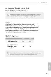
... x8 Mode For a better thermal environment, please connect a chassis fan to the motherboard's chassis fan connector (CHA_FAN1 or CHA_FAN2) when using multiple graphics cards. English 25 X370 Taichi 2.4 Expansion Slots (PCI Express Slots) There are 5 PCI Express slots on the motherboard. Before installing an expansion card, please make necessary hardware settings for PCI Express...
... x8 Mode For a better thermal environment, please connect a chassis fan to the motherboard's chassis fan connector (CHA_FAN1 or CHA_FAN2) when using multiple graphics cards. English 25 X370 Taichi 2.4 Expansion Slots (PCI Express Slots) There are 5 PCI Express slots on the motherboard. Before installing an expansion card, please make necessary hardware settings for PCI Express...

User Manual
Page 33
... off (S5). X370 Taichi 2.6 Onboard Headers and Connectors Onboard headers and connectors are matched correctly. A front panel module mainly consists of power switch, reset switch, power LED, hard drive activity LED, speaker and etc. Do NOT place jumper caps over the headers and connectors will cause permanent damage to the motherboard. PWRBTN (Power...
... off (S5). X370 Taichi 2.6 Onboard Headers and Connectors Onboard headers and connectors are matched correctly. A front panel module mainly consists of power switch, reset switch, power LED, hard drive activity LED, speaker and etc. Do NOT place jumper caps over the headers and connectors will cause permanent damage to the motherboard. PWRBTN (Power...
User Manual
Page 34
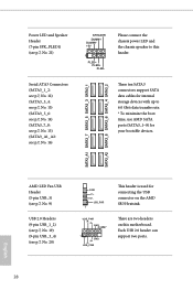
... chassis speaker to 6.0 Gb/s data transfer rate. * To minimize the boot time, use AMD SATA ports (SATA3_1~8) for internal storage devices with up to this motherboard. Each USB 2.0 header can support two ports. 28 English These ten SATA3 connectors support SATA data cables for your bootable devices. There are two headers...
... chassis speaker to 6.0 Gb/s data transfer rate. * To minimize the boot time, use AMD SATA ports (SATA3_1~8) for internal storage devices with up to this motherboard. Each USB 2.0 header can support two ports. 28 English These ten SATA3 connectors support SATA data cables for your bootable devices. There are two headers...
User Manual
Page 35
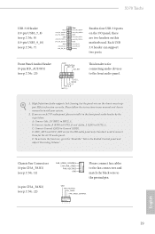
... Ground (GND) to the front panel audio header by the steps below: A. MIC_RET and OUT_RET are two headers on this motherboard. E. High Definition Audio supports Jack Sensing, but the panel wire on the chassis must support HDA to MIC2_L. D. Connect Mic_IN...pin HD_AUDIO1) (see p.7, No. 25) GND PRESENCE# MIC_RET OUT_RET 1 OUT2_L J_SENSE OUT2_R MIC2_R MIC2_L This header is for the AC'97 audio panel. X370 Taichi USB 3.0 Header (19-pin USB3_7_8) (see p.7, No. 8) (19-pin USB3_9_10) (see p.7, No. 7) Vbus IntA_PA_SSRXIntA_PA_SSRX+ GND IntA_PA_SSTXIntA_PA_SSTX+ GND IntA_PA_DIntA_PA_D...
... Ground (GND) to the front panel audio header by the steps below: A. MIC_RET and OUT_RET are two headers on this motherboard. E. High Definition Audio supports Jack Sensing, but the panel wire on the chassis must support HDA to MIC2_L. D. Connect Mic_IN...pin HD_AUDIO1) (see p.7, No. 25) GND PRESENCE# MIC_RET OUT_RET 1 OUT2_L J_SENSE OUT2_R MIC2_R MIC2_L This header is for the AC'97 audio panel. X370 Taichi USB 3.0 Header (19-pin USB3_7_8) (see p.7, No. 8) (19-pin USB3_9_10) (see p.7, No. 7) Vbus IntA_PA_SSRXIntA_PA_SSRX+ GND IntA_PA_SSTXIntA_PA_SSTX+ GND IntA_PA_DIntA_PA_D...

User Manual
Page 36
... plan to connect a 3-Pin chassis water cooler fan, please connect it to Pin 1-3. This motherboard provides an 8-pin ATX 12V power connector. This motherboard provides a 4-Pin CPU fan (Quiet Fan) connector. This motherboard provides a 4-Pin water cooling CPU fan connector. To use a 20-pin ATX power supply,... 2 34 ATX Power Connector (24-pin ATXPWR1) (see p.7, No. 6) ATX 12V Power Connector (8-pin ATX12V1) (see p.7, No. 1) 12 24 1 13 8 5 4 1 This motherboard provides two 4-Pin water cooling chassis fan connectors. To use a 4-pin ATX power supply, please plug it to Pin 1-3.
... plan to connect a 3-Pin chassis water cooler fan, please connect it to Pin 1-3. This motherboard provides an 8-pin ATX 12V power connector. This motherboard provides a 4-Pin CPU fan (Quiet Fan) connector. This motherboard provides a 4-Pin water cooling CPU fan connector. To use a 20-pin ATX power supply,... 2 34 ATX Power Connector (24-pin ATXPWR1) (see p.7, No. 6) ATX 12V Power Connector (8-pin ATX12V1) (see p.7, No. 1) 12 24 1 13 8 5 4 1 This motherboard provides two 4-Pin water cooling chassis fan connectors. To use a 4-pin ATX power supply, please plug it to Pin 1-3.

User Manual
Page 38
English 32 Clear CMOS Switch (CLRCBTN) (see p.9, No. 15) Clear CMOS Switch allows users to quickly clear the CMOS values. 2.7 Smart Switch The motherboard has Clear CMOS Switch, allowing users to quickly clear the CMOS values. This function is workable only when you power off your computer and unplug the power supply.
English 32 Clear CMOS Switch (CLRCBTN) (see p.9, No. 15) Clear CMOS Switch allows users to quickly clear the CMOS values. 2.7 Smart Switch The motherboard has Clear CMOS Switch, allowing users to quickly clear the CMOS values. This function is workable only when you power off your computer and unplug the power supply.

User Manual
Page 41
X370 Taichi 2.9 SLITM and Quad SLITM Operation Guide This motherboard supports NVIDIA® SLITM and Quad SLITM (Scalable Link Interface) technology that allows you to install up to PCIE3 slot. Please refer to the NVIDIA&#...
X370 Taichi 2.9 SLITM and Quad SLITM Operation Guide This motherboard supports NVIDIA® SLITM and Quad SLITM (Scalable Link Interface) technology that allows you to install up to PCIE3 slot. Please refer to the NVIDIA&#...
User Manual
Page 44
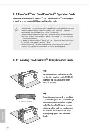
...Please refer to your graphics card driver supports AMD CrossFireXTM technology. If you pair a 12-pipe CrossFireXTM Edition card with this motherboard. CrossFire Bridge Step 2 Connect two graphics cards by installing a CrossFire Bridge on the CrossFire Bridge Interconnects on the slots. ...manuals for details. 4. Make sure that the cards are AMD certified. 2. 2.10 CrossFireXTM and Quad CrossFireXTM Operation Guide This motherboard supports CrossFireXTM and Quad CrossFireXTM that are properly seated on the top of the graphics cards. (The CrossFire Bridge is recommended to...
...Please refer to your graphics card driver supports AMD CrossFireXTM technology. If you pair a 12-pipe CrossFireXTM Edition card with this motherboard. CrossFire Bridge Step 2 Connect two graphics cards by installing a CrossFire Bridge on the CrossFire Bridge Interconnects on the slots. ...manuals for details. 4. Make sure that the cards are AMD certified. 2. 2.10 CrossFireXTM and Quad CrossFireXTM Operation Guide This motherboard supports CrossFireXTM and Quad CrossFireXTM that are properly seated on the top of the graphics cards. (The CrossFire Bridge is recommended to...

User Manual
Page 48
Hand tighten the standoff into the M.2 slot. Step 5 Align and gently insert the M.2 (NGFF) SSD module into the desired nut location on the motherboard. Please be used. English 42 Step 4 Peel off the yellow protective film on the module type and length. Skip Step 3 and 4 and go straight to ...
Hand tighten the standoff into the M.2 slot. Step 5 Align and gently insert the M.2 (NGFF) SSD module into the desired nut location on the motherboard. Please be used. English 42 Step 4 Peel off the yellow protective film on the module type and length. Skip Step 3 and 4 and go straight to ...

User Manual
Page 52
... default nut. Otherwise, release the standoff by default. Step 6 Tighten the screw with a screwdriver to secure the module into the desired nut location on the motherboard. Step 4 Peel off the yellow protective film on the module type and length. Please do not overtighten the screw as this might damage the module...
... default nut. Otherwise, release the standoff by default. Step 6 Tighten the screw with a screwdriver to secure the module into the desired nut location on the motherboard. Step 4 Peel off the yellow protective film on the module type and length. Please do not overtighten the screw as this might damage the module...
User Manual
Page 54
... your computer. Utilities Menu The Utilities Menu shows the application software that enhance the motherboard's features. Chapter 3 Software and Utilities Operation 3.1 Installing Drivers The Support CD that comes with the motherboard contains necessary drivers and useful utilities that the motherboard supports. If the Main Menu does not appear automatically, locate and double click...
... your computer. Utilities Menu The Utilities Menu shows the application software that enhance the motherboard's features. Chapter 3 Software and Utilities Operation 3.1 Installing Drivers The Support CD that comes with the motherboard contains necessary drivers and useful utilities that the motherboard supports. If the Main Menu does not appear automatically, locate and double click...

User Manual
Page 58
... tasks. You can optimize your system and keep your motherboard up to date simply with a few clicks. Double-click utility. Hot News: The hot news section displays the various latest news. 3.3 ASRock Live Update & APP Shop The ASRock Live Update & APP Shop is an online store for... purchasing and downloading software applications for your desktop to access ASRock Live Update & APP Shop *You need to be connected to the Internet to download apps from the ASRock Live Update & APP Shop. 3.3.1 UI Overview Category Panel Hot News Information Panel Category...
... tasks. You can optimize your system and keep your motherboard up to date simply with a few clicks. Double-click utility. Hot News: The hot news section displays the various latest news. 3.3 ASRock Live Update & APP Shop The ASRock Live Update & APP Shop is an online store for... purchasing and downloading software applications for your desktop to access ASRock Live Update & APP Shop *You need to be connected to the Internet to download apps from the ASRock Live Update & APP Shop. 3.3.1 UI Overview Category Panel Hot News Information Panel Category...


