
User Manual
Page 9
Nichicon Fine Gold Series Audio Caps - 120dB SNR DAC with LED (ACT/LINK LED and SPEED LED) • 1 x Clear CMOS Switch • HD Audio Jacks: Rear Speaker / Central / Bass / Line in / Front Speaker / Microphone (Gold Audio Jacks) 3 English Pure Power-In - Direct Drive Technology -...) • 1 x USB 3.1 Type-C Port (10 Gb/s) (Supports ESD Protection) • 6 x USB 3.0 Ports (Supports ESD Protection) • 1 x RJ-45 LAN Ports with Differential Amplifier - X370 Taichi • Supports Purity SoundTM 4 - TI® NE5532 Premium Headset Amplifier for R/L Audio Channel -
Nichicon Fine Gold Series Audio Caps - 120dB SNR DAC with LED (ACT/LINK LED and SPEED LED) • 1 x Clear CMOS Switch • HD Audio Jacks: Rear Speaker / Central / Bass / Line in / Front Speaker / Microphone (Gold Audio Jacks) 3 English Pure Power-In - Direct Drive Technology -...) • 1 x USB 3.1 Type-C Port (10 Gb/s) (Supports ESD Protection) • 6 x USB 3.0 Ports (Supports ESD Protection) • 1 x RJ-45 LAN Ports with Differential Amplifier - X370 Taichi • Supports Purity SoundTM 4 - TI® NE5532 Premium Headset Amplifier for R/L Audio Channel -
User Manual
Page 14
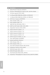
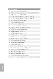
... Chassis Fan Connector (CHA_FAN1) 12 SATA3 Connectors (SATA3_1_2) 13 SATA3 Connectors (SATA3_3_4) 14 SATA3 Connectors (SATA3_5_6) 15 SATA3 Connectors (SATA3_7_8) 16 SATA3 Connectors (SATA3_A1_A2) 17 Clear CMOS Jumper (CLRMOS1) 18 System Panel Header (PANEL1) 19 USB 2.0 Header (USB_1_2) 20 USB 2.0 Header (USB_3_4) 21 Power LED and Speaker Header (SPK_PLED1) 22 Chassis Fan...
... Chassis Fan Connector (CHA_FAN1) 12 SATA3 Connectors (SATA3_1_2) 13 SATA3 Connectors (SATA3_3_4) 14 SATA3 Connectors (SATA3_5_6) 15 SATA3 Connectors (SATA3_7_8) 16 SATA3 Connectors (SATA3_A1_A2) 17 Clear CMOS Jumper (CLRMOS1) 18 System Panel Header (PANEL1) 19 USB 2.0 Header (USB_1_2) 20 USB 2.0 Header (USB_3_4) 21 Power LED and Speaker Header (SPK_PLED1) 22 Chassis Fan...
User Manual
Page 15
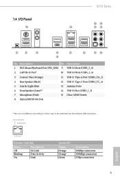
...) 15 Clear CMOS Switch 8 Optical SPDIF Out Port * There are two LEDs on each LAN port. ACT/LINK LED SPEED LED LAN Port Activity / Link LED Status Description Off Blinking On No Link Data Activity Link Speed LED Status Orange Orange Green Description 10Mbps connection 100Mbps connection 1Gbps connection 9 English 1.4 I/O Panel 1 X370 Taichi 35...
...) 15 Clear CMOS Switch 8 Optical SPDIF Out Port * There are two LEDs on each LAN port. ACT/LINK LED SPEED LED LAN Port Activity / Link LED Status Description Off Blinking On No Link Data Activity Link Speed LED Status Orange Orange Green Description 10Mbps connection 100Mbps connection 1Gbps connection 9 English 1.4 I/O Panel 1 X370 Taichi 35...

User Manual
Page 32
... from the power supply. However, please do the clear-CMOS action. The illustration shows a 3-pin jumper whose pin1 and pin2 are setup. Clear CMOS Jumper (CLRMOS1) (see p.7, No. 17) Default Clear CMOS CLRMOS1 allows you update the BIOS. To clear and reset the system parameters to clear the data in CMOS. 2.5 Jumpers Setup The illustration shows how jumpers are...
... from the power supply. However, please do the clear-CMOS action. The illustration shows a 3-pin jumper whose pin1 and pin2 are setup. Clear CMOS Jumper (CLRMOS1) (see p.7, No. 17) Default Clear CMOS CLRMOS1 allows you update the BIOS. To clear and reset the system parameters to clear the data in CMOS. 2.5 Jumpers Setup The illustration shows how jumpers are...

User Manual
Page 38
English 32 This function is workable only when you power off your computer and unplug the power supply. Clear CMOS Switch (CLRCBTN) (see p.9, No. 15) Clear CMOS Switch allows users to quickly clear the CMOS values. 2.7 Smart Switch The motherboard has Clear CMOS Switch, allowing users to quickly clear the CMOS values.
English 32 This function is workable only when you power off your computer and unplug the power supply. Clear CMOS Switch (CLRCBTN) (see p.9, No. 15) Clear CMOS Switch allows users to quickly clear the CMOS values. 2.7 Smart Switch The motherboard has Clear CMOS Switch, allowing users to quickly clear the CMOS values.
User Manual
Page 39
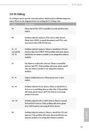
...exists, please install only one memory module or try using another VGA card. English 33 Please re-install the CPU and memory then clear CMOS. Please re-install the memory and CPU. A0 - Please re-install IDE and SATA devices. Please re-install the CPU and ...using other slots. If the problem still exists, please remove all SATA devices. X370 Taichi 2.8 Dr. Debug Dr. Debug is installed correctly and then clear CMOS. 0d Problem related to memory, VGA card or other devices. Please clear CMOS, re-install the memory and VGA card, and remove other USB, PCI devices...
...exists, please install only one memory module or try using another VGA card. English 33 Please re-install the CPU and memory then clear CMOS. Please re-install the memory and CPU. A0 - Please re-install IDE and SATA devices. Please re-install the CPU and ...using other slots. If the problem still exists, please remove all SATA devices. X370 Taichi 2.8 Dr. Debug Dr. Debug is installed correctly and then clear CMOS. 0d Problem related to memory, VGA card or other devices. Please clear CMOS, re-install the memory and VGA card, and remove other USB, PCI devices...

User Manual
Page 40
...installing the VGA card. d8 Invalid Password. Please try re-installing the keyboard and mouse. Please re-install the CPU and memory then clear CMOS. d7 The Keyboard and mouse could not be recognized. d6 The VGA could not be recognized. Please try removing all USB devices. ...FF Please check if the CPU is installed correctly and then clear CMOS. b4 Problem related to memory. English 34 If the problem still exists, please install only one memory module or try using other VGA...
...installing the VGA card. d8 Invalid Password. Please try re-installing the keyboard and mouse. Please re-install the CPU and memory then clear CMOS. d7 The Keyboard and mouse could not be recognized. d6 The VGA could not be recognized. Please try removing all USB devices. ...FF Please check if the CPU is installed correctly and then clear CMOS. b4 Problem related to memory. English 34 If the problem still exists, please install only one memory module or try using other VGA...
Quick Installation Guide
Page 4
... Chassis Fan Connector (CHA_FAN1) 12 SATA3 Connectors (SATA3_1_2) 13 SATA3 Connectors (SATA3_3_4) 14 SATA3 Connectors (SATA3_5_6) 15 SATA3 Connectors (SATA3_7_8) 16 SATA3 Connectors (SATA3_A1_A2) 17 Clear CMOS Jumper (CLRMOS1) 18 System Panel Header (PANEL1) 19 USB 2.0 Header (USB_1_2) 20 USB 2.0 Header (USB_3_4) 21 Power LED and Speaker Header (SPK_PLED1) 22 Chassis Fan...
... Chassis Fan Connector (CHA_FAN1) 12 SATA3 Connectors (SATA3_1_2) 13 SATA3 Connectors (SATA3_3_4) 14 SATA3 Connectors (SATA3_5_6) 15 SATA3 Connectors (SATA3_7_8) 16 SATA3 Connectors (SATA3_A1_A2) 17 Clear CMOS Jumper (CLRMOS1) 18 System Panel Header (PANEL1) 19 USB 2.0 Header (USB_1_2) 20 USB 2.0 Header (USB_3_4) 21 Power LED and Speaker Header (SPK_PLED1) 22 Chassis Fan...

Quick Installation Guide
Page 5
... USB 3.1 Type-C Port (USB31_TC_1) 5 Line In (Light Blue) 13 Antenna Ports 6 Front Speaker (Lime)** 14 USB 3.0 Port (USB3_1_2) 7 Microphone (Pink) 8 Optical SPDIF Out Port 15 Clear CMOS Switch * There are two LEDs on each LAN port. I/O Panel 1 X370 Taichi 35 2 46 15 14 13 11 10 12 9 87 No.
... USB 3.1 Type-C Port (USB31_TC_1) 5 Line In (Light Blue) 13 Antenna Ports 6 Front Speaker (Lime)** 14 USB 3.0 Port (USB3_1_2) 7 Microphone (Pink) 8 Optical SPDIF Out Port 15 Clear CMOS Switch * There are two LEDs on each LAN port. I/O Panel 1 X370 Taichi 35 2 46 15 14 13 11 10 12 9 87 No.

Quick Installation Guide
Page 9
... Sensing on Line Out port - X370 Taichi • Supports Purity SoundTM 4 - Direct Drive Technology - Individual PCB Layers for Front Panel Audio Connector (Supports up to 600 Ohm headsets) - Nichicon Fine Gold Series Audio Caps - 120dB SNR DAC with LED (ACT/LINK LED and SPEED LED) • 1 x Clear CMOS Switch • HD Audio Jacks: Rear...
... Sensing on Line Out port - X370 Taichi • Supports Purity SoundTM 4 - Direct Drive Technology - Individual PCB Layers for Front Panel Audio Connector (Supports up to 600 Ohm headsets) - Nichicon Fine Gold Series Audio Caps - 120dB SNR DAC with LED (ACT/LINK LED and SPEED LED) • 1 x Clear CMOS Switch • HD Audio Jacks: Rear...

Quick Installation Guide
Page 28
... and pin3 on the pins, the jumper is "Open". English 26 However, please do not clear the CMOS right after you do the clear-CMOS action. When the jumper cap is removed. Clear CMOS Jumper (CLRMOS1) (see p.7, No. 17) Default Clear CMOS CLRMOS1 allows you to default setup, please turn off the computer and unplug the power cord...
... and pin3 on the pins, the jumper is "Open". English 26 However, please do not clear the CMOS right after you do the clear-CMOS action. When the jumper cap is removed. Clear CMOS Jumper (CLRMOS1) (see p.7, No. 17) Default Clear CMOS CLRMOS1 allows you to default setup, please turn off the computer and unplug the power cord...

Quick Installation Guide
Page 34
English 32 Clear CMOS Switch (CLRCBTN) (see p.9, No. 15) Clear CMOS Switch allows users to quickly clear the CMOS values. This function is workable only when you power off your computer and unplug the power supply. 2.7 Smart Switch The motherboard has Clear CMOS Switch, allowing users to quickly clear the CMOS values.
English 32 Clear CMOS Switch (CLRCBTN) (see p.9, No. 15) Clear CMOS Switch allows users to quickly clear the CMOS values. This function is workable only when you power off your computer and unplug the power supply. 2.7 Smart Switch The motherboard has Clear CMOS Switch, allowing users to quickly clear the CMOS values.

Quick Installation Guide
Page 133
한국어 X370 Taichi LAN 무선 LAN I/O 120dB SNR DAC TI® NE5532 600 PCB R/L PCB 15 DTS • Gigabit LAN 10/100/1000 Mb/s • GigaLAN Intel&#...; 1 개 (10 Gb/s) (ESD USB 3.0 포트 6 개 (ESD LED 장착 RJ-45 LAN 포트 1 개 (ACT/LINK LED 및 SPEED LED) • Clear CMOS 스위치 1 개 • HD 131
한국어 X370 Taichi LAN 무선 LAN I/O 120dB SNR DAC TI® NE5532 600 PCB R/L PCB 15 DTS • Gigabit LAN 10/100/1000 Mb/s • GigaLAN Intel&#...; 1 개 (10 Gb/s) (ESD USB 3.0 포트 6 개 (ESD LED 장착 RJ-45 LAN 포트 1 개 (ACT/LINK LED 및 SPEED LED) • Clear CMOS 스위치 1 개 • HD 131

