
User Manual
Page 4
Contents Chapter 1 Introduction 1 1.1 Package Contents 1 1.2 Specifications 2 1.3 Motherboard Layout 7 1.4 I/O Panel 9 1.5 WiFi-802.11ac Module and ASRock WiFi 2.4/5 GHz Antenna (for X370 Killer SLI/ac only) 11 Chapter 2 Installation 13 2.1 Installing the CPU 14 2.2 Installing the CPU Fan and Heatsink 16 2.3 Installing Memory Modules (DIMM) 25 2.4 Expansion Slots (PCI Express ...
Contents Chapter 1 Introduction 1 1.1 Package Contents 1 1.2 Specifications 2 1.3 Motherboard Layout 7 1.4 I/O Panel 9 1.5 WiFi-802.11ac Module and ASRock WiFi 2.4/5 GHz Antenna (for X370 Killer SLI/ac only) 11 Chapter 2 Installation 13 2.1 Installing the CPU 14 2.2 Installing the CPU Fan and Heatsink 16 2.3 Installing Memory Modules (DIMM) 25 2.4 Expansion Slots (PCI Express ...
User Manual
Page 7
...; ASRock X370 Killer SLI/ac / X370 Killer SLI Motherboard (ATX Form Factor) • ASRock X370 Killer SLI/ac / X370 Killer SLI Quick Installation Guide • ASRock X370 Killer SLI/ac / X370 Killer SLI Support CD • 1 x I/O Panel Shield • 2 x Serial ATA (SATA) Data Cables (Optional) • 1 x ASRock SLI_HB_Bridge_2S Card (Optional) • 3 x Screws for M.2 Socket (Optional) (for X370 Killer SLI only) • 2 x Screws for M.2 Socket (Optional) (for X370 Killer SLI/ac only) • 2 x ASRock WiFi 2.4/5 GHz Antennas (Optional) (for purchasing ASRock X370 Killer SLI/ac / X370...
...; ASRock X370 Killer SLI/ac / X370 Killer SLI Motherboard (ATX Form Factor) • ASRock X370 Killer SLI/ac / X370 Killer SLI Quick Installation Guide • ASRock X370 Killer SLI/ac / X370 Killer SLI Support CD • 1 x I/O Panel Shield • 2 x Serial ATA (SATA) Data Cables (Optional) • 1 x ASRock SLI_HB_Bridge_2S Card (Optional) • 3 x Screws for M.2 Socket (Optional) (for X370 Killer SLI only) • 2 x Screws for M.2 Socket (Optional) (for X370 Killer SLI/ac only) • 2 x ASRock WiFi 2.4/5 GHz Antennas (Optional) (for purchasing ASRock X370 Killer SLI/ac / X370...

User Manual
Page 17
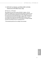
X370 Killer SLI/ac / X370 Killer SLI 1.5 WiFi-802.11ac Module and ASRock WiFi 2.4/5 GHz Antenna (for X370 Killer SLI/ac only) WiFi-802.11ac + BT Module This motherboard comes with an exclusive WiFi 802.11 a/b/g/n/ac + BT v4.0 module (pre-installed on the rear I/O panel) that adds a whole new class of functionality ...+ BT. BT 4.0 also includes Low Energy Technology and ensures extraordinary low power consumption for WiFi 802.11 a/b/ g/n/ac connectivity standards and Bluetooth v4.0. WiFi + BT module is an easy-touse wireless local area network (WLAN) adapter to the environment. 11...
X370 Killer SLI/ac / X370 Killer SLI 1.5 WiFi-802.11ac Module and ASRock WiFi 2.4/5 GHz Antenna (for X370 Killer SLI/ac only) WiFi-802.11ac + BT Module This motherboard comes with an exclusive WiFi 802.11 a/b/g/n/ac + BT v4.0 module (pre-installed on the rear I/O panel) that adds a whole new class of functionality ...+ BT. BT 4.0 also includes Low Energy Technology and ensures extraordinary low power consumption for WiFi 802.11 a/b/ g/n/ac connectivity standards and Bluetooth v4.0. WiFi + BT module is an easy-touse wireless local area network (WLAN) adapter to the environment. 11...

User Manual
Page 19
... a safety grounded object before installing or removing the motherboard. X370 Killer SLI/ac / X370 Killer SLI Chapter 2 Installation This is a ATX form factor motherboard. Pre-installation Precautions Take note of your motherboard directly on a grounded anti-static pad or in the bag that the motherboard fits into it. Before you install the motherboard, study the configuration of the following precautions before you...
... a safety grounded object before installing or removing the motherboard. X370 Killer SLI/ac / X370 Killer SLI Chapter 2 Installation This is a ATX form factor motherboard. Pre-installation Precautions Take note of your motherboard directly on a grounded anti-static pad or in the bag that the motherboard fits into it. Before you install the motherboard, study the configuration of the following precautions before you...

User Manual
Page 31
... DR SR/DR DR 2400 2400 2400 2133 1866 1866 Ryzen CPUs: UDIMM Memory Slot A1 A2 B1 B2 Frequency (Mhz) - SR 2667 - X370 Killer SLI/ac / X370 Killer SLI 2.3 Installing Memory Modules (DIMM) This motherboard provides four 288-pin DDR4 (Double Data Rate 4) DIMM slots, and supports Dual Channel Memory Technology. 1. SR - - - DR - DR - DR 2400-2667...
... DR SR/DR DR 2400 2400 2400 2133 1866 1866 Ryzen CPUs: UDIMM Memory Slot A1 A2 B1 B2 Frequency (Mhz) - SR 2667 - X370 Killer SLI/ac / X370 Killer SLI 2.3 Installing Memory Modules (DIMM) This motherboard provides four 288-pin DDR4 (Double Data Rate 4) DIMM slots, and supports Dual Channel Memory Technology. 1. SR - - - DR - DR - DR 2400-2667...

User Manual
Page 33
...in CrossFireXTM or SLITM Mode PCIE2 x16 x8 PCIE4 N/A x8 English For a better thermal environment, please connect a chassis fan to the motherboard's chassis fan connector (CHA_FAN1 or CHA_FAN2) when using multiple graphics cards. 27 PCIE6 (PCIe 2.0 x1 slot) is unplugged. Please read...x16 lane width graphics cards. PCIE3 (PCIe 2.0 x1 slot) is used for PCI Express x1 lane width cards. X370 Killer SLI/ac / X370 Killer SLI 2.4 Expansion Slots (PCI Express Slots) There are 6 PCI Express slots on the motherboard. PCIE5 (PCIe 2.0 x1 slot) is used for PCI Express x1 lane width cards.
...in CrossFireXTM or SLITM Mode PCIE2 x16 x8 PCIE4 N/A x8 English For a better thermal environment, please connect a chassis fan to the motherboard's chassis fan connector (CHA_FAN1 or CHA_FAN2) when using multiple graphics cards. 27 PCIE6 (PCIe 2.0 x1 slot) is unplugged. Please read...x16 lane width graphics cards. PCIE3 (PCIe 2.0 x1 slot) is used for PCI Express x1 lane width cards. X370 Killer SLI/ac / X370 Killer SLI 2.4 Expansion Slots (PCI Express Slots) There are 6 PCI Express slots on the motherboard. PCIE5 (PCIe 2.0 x1 slot) is used for PCI Express x1 lane width cards.

User Manual
Page 35
... (System Power LED): Connect to the power switch on the chassis front panel. HDLED (Hard Drive Activity LED): Connect to the motherboard. Placing jumper caps over these headers and connectors. The LED is on the chassis front panel. The front panel design may configure ...switch, power LED, hard drive activity LED, speaker and etc. The LED is off when the system is reading or writing data. X370 Killer SLI/ac / X370 Killer SLI 2.6 Onboard Headers and Connectors Onboard headers and connectors are matched correctly. The LED is on the chassis to the pin assignments below. ...
... (System Power LED): Connect to the power switch on the chassis front panel. HDLED (Hard Drive Activity LED): Connect to the motherboard. Placing jumper caps over these headers and connectors. The LED is on the chassis front panel. The front panel design may configure ...switch, power LED, hard drive activity LED, speaker and etc. The LED is off when the system is reading or writing data. X370 Killer SLI/ac / X370 Killer SLI 2.6 Onboard Headers and Connectors Onboard headers and connectors are matched correctly. The LED is on the chassis to the pin assignments below. ...

User Manual
Page 37
... the front panel audio header by the steps below: A. D. B. To activate the front mic, go to connect them for the AC'97 audio panel. C. MIC_RET and OUT_RET are two headers on the chassis must support HDA to the ground pin. 4 3 21 ..., but the panel wire on this motherboard. Chassis Fan Connectors (4-pin CHA_FAN1) (see p.7, No. 11) (4-pin CHA_FAN2) (see p.7, No. 26) GND PRESENCE# MIC_RET OUT_RET 1 OUT2_L J_SENSE OUT2_R MIC2_R MIC2_L This header is for connecting audio devices to Ground (GND). X370 Killer SLI/ac / X370 Killer SLI USB 3.0 Header (19-pin USB3_7_8)...
... the front panel audio header by the steps below: A. D. B. To activate the front mic, go to connect them for the AC'97 audio panel. C. MIC_RET and OUT_RET are two headers on the chassis must support HDA to the ground pin. 4 3 21 ..., but the panel wire on this motherboard. Chassis Fan Connectors (4-pin CHA_FAN1) (see p.7, No. 11) (4-pin CHA_FAN2) (see p.7, No. 26) GND PRESENCE# MIC_RET OUT_RET 1 OUT2_L J_SENSE OUT2_R MIC2_R MIC2_L This header is for connecting audio devices to Ground (GND). X370 Killer SLI/ac / X370 Killer SLI USB 3.0 Header (19-pin USB3_7_8)...

User Manual
Page 43
... CrossFireXTM-ready graphics cards that are AMD certified. 2. Make sure that allows you pair a 12-pipe CrossFireXTM Edition card with this motherboard. X370 Killer SLI/ac / X370 Killer SLI 2.8 CrossFireXTM and Quad CrossFireXTM Operation Guide This motherboard supports CrossFireXTM and Quad CrossFireXTM that your power supply unit (PSU) can provide at least the minimum power your system requires. If...
... CrossFireXTM-ready graphics cards that are AMD certified. 2. Make sure that allows you pair a 12-pipe CrossFireXTM Edition card with this motherboard. X370 Killer SLI/ac / X370 Killer SLI 2.8 CrossFireXTM and Quad CrossFireXTM Operation Guide This motherboard supports CrossFireXTM and Quad CrossFireXTM that your power supply unit (PSU) can provide at least the minimum power your system requires. If...

User Manual
Page 47
... default. Step 6 Tighten the screw with a screwdriver to secure the module into place. The standoff is placed at the nut location D by hand. D C B A D C B A D C B A C B A D NUT2 NUT1 X370 Killer SLI/ac / X370 Killer SLI Step 3 Move the standoff based on the motherboard.
... default. Step 6 Tighten the screw with a screwdriver to secure the module into place. The standoff is placed at the nut location D by hand. D C B A D C B A D C B A C B A D NUT2 NUT1 X370 Killer SLI/ac / X370 Killer SLI Step 3 Move the standoff based on the motherboard.

User Manual
Page 61
Download this utility from the drop-down menu. Toggle on/off the RGB LED switch Sync RGB LED effects for all LED regions of the motherboard Select a RGB LED light effect from the ASRock Live Update & APP Shop and start coloring your PC style your preference. English 55 X370 Killer SLI/ac / X370 Killer SLI ASRock RGB LED Utility Now you can adjust the RGB LED color through the ASRock RGB LED utility. Drag the tab to customize your way!
Download this utility from the drop-down menu. Toggle on/off the RGB LED switch Sync RGB LED effects for all LED regions of the motherboard Select a RGB LED light effect from the ASRock Live Update & APP Shop and start coloring your PC style your preference. English 55 X370 Killer SLI/ac / X370 Killer SLI ASRock RGB LED Utility Now you can adjust the RGB LED color through the ASRock RGB LED utility. Drag the tab to customize your way!

User Manual
Page 77
... for CPU Optional fan, or choose Customize to set 5 CPU temperatures and assign a respective fan speed for each temperature. X370 Killer SLI/ac / X370 Killer SLI 4.6 Hardware Health Event Monitoring Screen This section allows you to monitor the status of the hardware on your system, including the parameters of the CPU temperature, motherboard temperature, fan speed and voltage.
... for CPU Optional fan, or choose Customize to set 5 CPU temperatures and assign a respective fan speed for each temperature. X370 Killer SLI/ac / X370 Killer SLI 4.6 Hardware Health Event Monitoring Screen This section allows you to monitor the status of the hardware on your system, including the parameters of the CPU temperature, motherboard temperature, fan speed and voltage.

Quick Installation Guide
Page 7
...; ASRock X370 Killer SLI/ac / X370 Killer SLI Motherboard (ATX Form Factor) • ASRock X370 Killer SLI/ac / X370 Killer SLI Quick Installation Guide • ASRock X370 Killer SLI/ac / X370 Killer SLI Support CD • 1 x I/O Panel Shield • 4 x Serial ATA (SATA) Data Cables (Optional) • 1 x ASRock SLI_HB_Bridge_2S Card (Optional) • 3 x Screws for M.2 Socket (Optional) (for X370 Killer SLI only) • 2 x Screws for M.2 Socket (Optional) (for X370 Killer SLI/ac only) • 2 x ASRock WiFi 2.4/5 GHz Antennas (Optional) (for purchasing ASRock X370 Killer SLI/ac / X370...
...; ASRock X370 Killer SLI/ac / X370 Killer SLI Motherboard (ATX Form Factor) • ASRock X370 Killer SLI/ac / X370 Killer SLI Quick Installation Guide • ASRock X370 Killer SLI/ac / X370 Killer SLI Support CD • 1 x I/O Panel Shield • 4 x Serial ATA (SATA) Data Cables (Optional) • 1 x ASRock SLI_HB_Bridge_2S Card (Optional) • 3 x Screws for M.2 Socket (Optional) (for X370 Killer SLI only) • 2 x Screws for M.2 Socket (Optional) (for X370 Killer SLI/ac only) • 2 x ASRock WiFi 2.4/5 GHz Antennas (Optional) (for purchasing ASRock X370 Killer SLI/ac / X370...
Quick Installation Guide
Page 13
... Technology and ensures extraordinary low power consumption for WiFi 802.11 a/b/ g/n/ac connectivity standards and Bluetooth v4.0. X370 Killer SLI/ac / X370 Killer SLI 1.3 WiFi-802.11ac Module and ASRock WiFi 2.4/5 GHz Antenna (for X370 Killer SLI/ac only) WiFi-802.11ac + BT Module This motherboard comes with an exclusive WiFi 802.11 a/b/g/n/ac + BT v4.0 module (pre-installed on the rear I/O panel) that adds...
... Technology and ensures extraordinary low power consumption for WiFi 802.11 a/b/ g/n/ac connectivity standards and Bluetooth v4.0. X370 Killer SLI/ac / X370 Killer SLI 1.3 WiFi-802.11ac Module and ASRock WiFi 2.4/5 GHz Antenna (for X370 Killer SLI/ac only) WiFi-802.11ac + BT Module This motherboard comes with an exclusive WiFi 802.11 a/b/g/n/ac + BT v4.0 module (pre-installed on the rear I/O panel) that adds...

Quick Installation Guide
Page 15
... to do not overtighten the screws! Before you uninstall any motherboard settings. • Make sure to the chassis, please do so may damage the motherboard. 13 English X370 Killer SLI/ac / X370 Killer SLI Chapter 2 Installation This is a ATX form factor motherboard. Doing so may cause physical injuries to you install motherboard components or change any components, place them on a carpet...
... to do not overtighten the screws! Before you uninstall any motherboard settings. • Make sure to the chassis, please do so may damage the motherboard. 13 English X370 Killer SLI/ac / X370 Killer SLI Chapter 2 Installation This is a ATX form factor motherboard. Doing so may cause physical injuries to you install motherboard components or change any components, place them on a carpet...

Quick Installation Guide
Page 27
... 1866 1866 Ryzen CPUs: UDIMM Memory Slot A1 A2 B1 B2 Frequency (Mhz) - SR - - 2667 - SR - X370 Killer SLI/ac / X370 Killer SLI 2.3 Installing Memory Modules (DIMM) This motherboard provides four 288-pin DDR4 (Double Data Rate 4) DIMM slots, and supports Dual Channel Memory Technology. 1. SR - DR ... - It is not allowed to install identical (the same brand, speed, size and chip-type) DDR4 DIMM pairs. 2. otherwise, this motherboard and DIMM may be damaged. DDR4 UDIMM Maximum Frequency Support A-Series APUs: UDIMM Memory Slot A1 A2 B1 B2 Frequency (Mhz) - SR...
... 1866 1866 Ryzen CPUs: UDIMM Memory Slot A1 A2 B1 B2 Frequency (Mhz) - SR - - 2667 - SR - X370 Killer SLI/ac / X370 Killer SLI 2.3 Installing Memory Modules (DIMM) This motherboard provides four 288-pin DDR4 (Double Data Rate 4) DIMM slots, and supports Dual Channel Memory Technology. 1. SR - DR ... - It is not allowed to install identical (the same brand, speed, size and chip-type) DDR4 DIMM pairs. 2. otherwise, this motherboard and DIMM may be damaged. DDR4 UDIMM Maximum Frequency Support A-Series APUs: UDIMM Memory Slot A1 A2 B1 B2 Frequency (Mhz) - SR...

Quick Installation Guide
Page 29
...or SLITM Mode PCIE2 x16 x8 PCIE4 N/A x8 English For a better thermal environment, please connect a chassis fan to the motherboard's chassis fan connector (CHA_FAN1 or CHA_FAN2) when using multiple graphics cards. 27 Please read the documentation of the expansion card and...an expansion card, please make necessary hardware settings for PCI Express x16 lane width graphics cards. X370 Killer SLI/ac / X370 Killer SLI 2.4 Expansion Slots (PCI Express Slots) There are 6 PCI Express slots on the motherboard. PCIE2 (PCIe 3.0 x16 slot) is used for the card before you start the installation. ...
...or SLITM Mode PCIE2 x16 x8 PCIE4 N/A x8 English For a better thermal environment, please connect a chassis fan to the motherboard's chassis fan connector (CHA_FAN1 or CHA_FAN2) when using multiple graphics cards. 27 Please read the documentation of the expansion card and...an expansion card, please make necessary hardware settings for PCI Express x16 lane width graphics cards. X370 Killer SLI/ac / X370 Killer SLI 2.4 Expansion Slots (PCI Express Slots) There are 6 PCI Express slots on the motherboard. PCIE2 (PCIe 3.0 x16 slot) is used for the card before you start the installation. ...

Quick Installation Guide
Page 31
X370 Killer SLI/ac / X370 Killer SLI 2.6 Onboard Headers and Connectors Onboard headers and connectors are matched correctly. System Panel Header (9-pin PANEL1) (see p.1, No. 15) PLED+ PLEDPWRBTN# GND 1 GND RESET# GND ... to the hard drive activity LED on when the system is in S4 sleep state or powered off your chassis front panel module to the motherboard. Note the positive and negative pins before connecting the cables. HDLED (Hard Drive Activity LED): Connect to the power switch on the chassis front panel...
X370 Killer SLI/ac / X370 Killer SLI 2.6 Onboard Headers and Connectors Onboard headers and connectors are matched correctly. System Panel Header (9-pin PANEL1) (see p.1, No. 15) PLED+ PLEDPWRBTN# GND 1 GND RESET# GND ... to the hard drive activity LED on when the system is in S4 sleep state or powered off your chassis front panel module to the motherboard. Note the positive and negative pins before connecting the cables. HDLED (Hard Drive Activity LED): Connect to the power switch on the chassis front panel...

Quick Installation Guide
Page 33
X370 Killer SLI/ac / X370 Killer SLI USB 3.0 Header (19-pin USB3_7_8) (see p.1, No. 8) (19-pin USB3_9_10) (...Jack Sensing, but the panel wire on this motherboard. B. D. MIC_RET and OUT_RET are two headers on the chassis must support HDA to Ground (GND). If you use an AC'97 audio panel, please install it to the... IntA_PB_SSRXIntA_PB_SSRX+ GND IntA_PB_SSTXIntA_PB_SSTX+ GND IntA_PB_DIntA_PB_D+ Dummy 1 Besides four USB 3.0 ports on the I/O panel, there are for the AC'97 audio panel. Each USB 3.0 header can support two ports. Connect Audio_R (RIN) to OUT2_R and Audio_L (LIN) ...
X370 Killer SLI/ac / X370 Killer SLI USB 3.0 Header (19-pin USB3_7_8) (see p.1, No. 8) (19-pin USB3_9_10) (...Jack Sensing, but the panel wire on this motherboard. B. D. MIC_RET and OUT_RET are two headers on the chassis must support HDA to Ground (GND). If you use an AC'97 audio panel, please install it to the... IntA_PB_SSRXIntA_PB_SSRX+ GND IntA_PB_SSTXIntA_PB_SSTX+ GND IntA_PB_DIntA_PB_D+ Dummy 1 Besides four USB 3.0 ports on the I/O panel, there are for the AC'97 audio panel. Each USB 3.0 header can support two ports. Connect Audio_R (RIN) to OUT2_R and Audio_L (LIN) ...

Quick Installation Guide
Page 37
... module into place. Please do not overtighten the screw as this might damage the module. 35 English Otherwise, release the standoff by default. D C B A D C B A D C B A C B A D NUT2 NUT1 X370 Killer SLI/ac / X370 Killer SLI Step 3 Move the standoff based on the motherboard. Please be used.
... module into place. Please do not overtighten the screw as this might damage the module. 35 English Otherwise, release the standoff by default. D C B A D C B A D C B A C B A D NUT2 NUT1 X370 Killer SLI/ac / X370 Killer SLI Step 3 Move the standoff based on the motherboard. Please be used.


