
User Manual
Page 4
... Package Contents 1 1.2 Specifications 2 1.3 Motherboard Layout 7 1.4 I/O Panel 9 1.5 WiFi-802.11ac Module and ASRock WiFi 2.4/5 GHz Antenna (for X370 Killer SLI/ac only) 11 Chapter 2 Installation 13 2.1 Installing the CPU 14 2.2 Installing the CPU Fan and Heatsink 16 2.3 Installing Memory Modules (DIMM) 25 2.4 Expansion Slots (PCI Express Slots) 27 2.5 Jumpers Setup 28 2.6 Onboard Headers and Connectors 29 2.7 SLITM and Quad SLITM Operation Guide 34 2.7.1 Installing Two SLITM-Ready Graphics Cards 34 2.7.2 Driver Installation and Setup 36 2.8 CrossFireXTM and...
... Package Contents 1 1.2 Specifications 2 1.3 Motherboard Layout 7 1.4 I/O Panel 9 1.5 WiFi-802.11ac Module and ASRock WiFi 2.4/5 GHz Antenna (for X370 Killer SLI/ac only) 11 Chapter 2 Installation 13 2.1 Installing the CPU 14 2.2 Installing the CPU Fan and Heatsink 16 2.3 Installing Memory Modules (DIMM) 25 2.4 Expansion Slots (PCI Express Slots) 27 2.5 Jumpers Setup 28 2.6 Onboard Headers and Connectors 29 2.7 SLITM and Quad SLITM Operation Guide 34 2.7.1 Installing Two SLITM-Ready Graphics Cards 34 2.7.2 Driver Installation and Setup 36 2.8 CrossFireXTM and...
User Manual
Page 7
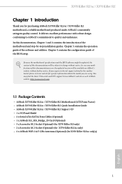
... the motherboard and step-by-step installation guides. Because the motherboard specifications and the BIOS software might be subject to quality and endurance. You may find the latest VGA cards and CPU support list on ASRock's website without notice. In case any modifications of this documentation, Chapter 1 and 2 contains the introduction of this motherboard, please visit our website for specific information about the model you for X370 Killer SLI/ac...
... the motherboard and step-by-step installation guides. Because the motherboard specifications and the BIOS software might be subject to quality and endurance. You may find the latest VGA cards and CPU support list on ASRock's website without notice. In case any modifications of this documentation, Chapter 1 and 2 contains the introduction of this motherboard, please visit our website for specific information about the model you for X370 Killer SLI/ac...

User Manual
Page 11
... Killer SLI/ac / X370 Killer SLI • 1 x Chassis Optional/Water Pump Fan Connector (4-pin) (Smart Fan Speed Control) * The Chassis Optional/Water Pump Fan supports the water cooler fan of maximum 1.5A (18W) fan power. * CHA_FAN2 can auto detect if 3-pin or 4-pin fan is in use. • 1 x 24 pin ATX Power Connector (Hi-Density Power Connector) • 1 x 8 pin 12V Power Connector (Hi-Density Power Connector) • 1 x Front Panel Audio Connector • 1 x AMD LED Fan USB Header • 2 x USB 2.0 Headers (Support 4 USB 2.0 ports) (Supports ESD Protection) • 2 x USB 3.0 Headers...
... Killer SLI/ac / X370 Killer SLI • 1 x Chassis Optional/Water Pump Fan Connector (4-pin) (Smart Fan Speed Control) * The Chassis Optional/Water Pump Fan supports the water cooler fan of maximum 1.5A (18W) fan power. * CHA_FAN2 can auto detect if 3-pin or 4-pin fan is in use. • 1 x 24 pin ATX Power Connector (Hi-Density Power Connector) • 1 x 8 pin 12V Power Connector (Hi-Density Power Connector) • 1 x Front Panel Audio Connector • 1 x AMD LED Fan USB Header • 2 x USB 2.0 Headers (Support 4 USB 2.0 ports) (Supports ESD Protection) • 2 x USB 3.0 Headers...

User Manual
Page 14
... Fan Connector (CPU_FAN1) 3 CPU Fan / Waterpump Fan Connector (CPU_OPT/W_PUMP) 4 2 x 288-pin DDR4 DIMM Slots (DDR4_A1, DDR4_B1) 5 2 x 288-pin DDR4 DIMM Slots (DDR4_A2, DDR4_B2) 6 ATX Power Connector (ATXPWR1) 7 USB 3.0 Header (USB3_9_10) 8 USB 3.0 Header (USB3_7_8) 9 AMD LED Fan USB Header (USB_5) 10 AMD Fan LED Header (AMD_FAN_LED1) 11 Chassis Fan Connector (CHA_FAN1) 12 SATA3 Connectors (SATA3_5_6) 13 SATA3 Connectors (SATA3_3_4) 14 SATA3 Connectors (SATA3_1_2) 15 System Panel Header (PANEL1) 16 RGB LED Header (RGB_LED1) 17 RGB LED Header (RGB_LED2) 18 Clear CMOS Jumper (CLRMOS1) 19 Chassis...
... Fan Connector (CPU_FAN1) 3 CPU Fan / Waterpump Fan Connector (CPU_OPT/W_PUMP) 4 2 x 288-pin DDR4 DIMM Slots (DDR4_A1, DDR4_B1) 5 2 x 288-pin DDR4 DIMM Slots (DDR4_A2, DDR4_B2) 6 ATX Power Connector (ATXPWR1) 7 USB 3.0 Header (USB3_9_10) 8 USB 3.0 Header (USB3_7_8) 9 AMD LED Fan USB Header (USB_5) 10 AMD Fan LED Header (AMD_FAN_LED1) 11 Chassis Fan Connector (CHA_FAN1) 12 SATA3 Connectors (SATA3_5_6) 13 SATA3 Connectors (SATA3_3_4) 14 SATA3 Connectors (SATA3_1_2) 15 System Panel Header (PANEL1) 16 RGB LED Header (RGB_LED1) 17 RGB LED Header (RGB_LED2) 18 Clear CMOS Jumper (CLRMOS1) 19 Chassis...

User Manual
Page 33
... connect a chassis fan to the motherboard's chassis fan connector (CHA_FAN1 or CHA_FAN2) when using multiple graphics cards. 27 Please read the documentation of the expansion card and make sure that the power supply is switched off or the power cord is unplugged. PCIE2 (PCIe 3.0 x16 slot) is used for PCI Express x8 lane width graphics cards. PCIE4 (PCIe 3.0 x16 slot) is used for PCI Express x16 lane width graphics cards. PCIE3 (PCIe 2.0 x1 slot) is used for the card before you start the installation. X370 Killer SLI/ac / X370 Killer SLI...
... connect a chassis fan to the motherboard's chassis fan connector (CHA_FAN1 or CHA_FAN2) when using multiple graphics cards. 27 Please read the documentation of the expansion card and make sure that the power supply is switched off or the power cord is unplugged. PCIE2 (PCIe 3.0 x16 slot) is used for PCI Express x8 lane width graphics cards. PCIE4 (PCIe 3.0 x16 slot) is used for PCI Express x16 lane width graphics cards. PCIE3 (PCIe 2.0 x1 slot) is used for the card before you start the installation. X370 Killer SLI/ac / X370 Killer SLI...

User Manual
Page 36
... chassis power LED and the chassis speaker to 6.0 Gb/s data transfer rate. SATA3_6 These six SATA3 connectors support SATA data cables for connecting the USB connector on this header. USB 2.0 Headers ((9-pin USB_1_2) (see p.7, No. 21) (9-pin USB_3_4) (see p.7, No. 22) USB_PWR PP+ GND DUMMY 1 GND P+ PUSB_PWR There are two headers on the AMD SR3 Heatsink. P+ USB_PWR This header is used for internal storage devices with up to this motherboard. Power LED and Speaker Header (7-pin SPK_PLED1) (see p.7, No. 23) Serial ATA3 Connectors...
... chassis power LED and the chassis speaker to 6.0 Gb/s data transfer rate. SATA3_6 These six SATA3 connectors support SATA data cables for connecting the USB connector on this header. USB 2.0 Headers ((9-pin USB_1_2) (see p.7, No. 21) (9-pin USB_3_4) (see p.7, No. 22) USB_PWR PP+ GND DUMMY 1 GND P+ PUSB_PWR There are two headers on the AMD SR3 Heatsink. P+ USB_PWR This header is used for internal storage devices with up to this motherboard. Power LED and Speaker Header (7-pin SPK_PLED1) (see p.7, No. 23) Serial ATA3 Connectors...

User Manual
Page 43
... of the graphics cards. (The CrossFire Bridge is recommended to your graphics card driver supports AMD CrossFireXTM technology. Download the drivers from the AMD's website: www.amd.com 3. Make sure that the cards are AMD certified. 2. CrossFire Bridge Step 2 Connect two graphics cards by installing a CrossFire Bridge on the CrossFire Bridge Interconnects on the slots. You should only use a AMD certified PSU. X370 Killer SLI/ac / X370 Killer SLI 2.8 CrossFireXTM and Quad CrossFireXTM Operation Guide This motherboard supports CrossFireXTM and...
... of the graphics cards. (The CrossFire Bridge is recommended to your graphics card driver supports AMD CrossFireXTM technology. Download the drivers from the AMD's website: www.amd.com 3. Make sure that the cards are AMD certified. 2. CrossFire Bridge Step 2 Connect two graphics cards by installing a CrossFire Bridge on the CrossFire Bridge Interconnects on the slots. You should only use a AMD certified PSU. X370 Killer SLI/ac / X370 Killer SLI 2.8 CrossFireXTM and Quad CrossFireXTM Operation Guide This motherboard supports CrossFireXTM and...
User Manual
Page 45
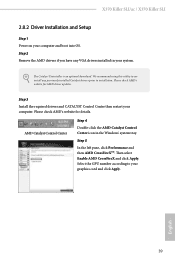
... / X370 Killer SLI 2.8.2 Driver Installation and Setup Step 1 Power on your graphics card and click Apply. We recommend using this utility to your computer and boot into OS. Select the GPU number according to uninstall any VGA drivers installed in the Windows® system tray. The Catalyst Uninstaller is an optional download. Then select Enable AMD CrossFireX and click Apply. Please check AMD's website for details. Step 3 Install the required drivers and CATALYST Control...
... / X370 Killer SLI 2.8.2 Driver Installation and Setup Step 1 Power on your graphics card and click Apply. We recommend using this utility to your computer and boot into OS. Select the GPU number according to uninstall any VGA drivers installed in the Windows® system tray. The Catalyst Uninstaller is an optional download. Then select Enable AMD CrossFireX and click Apply. Please check AMD's website for details. Step 3 Install the required drivers and CATALYST Control...
User Manual
Page 50
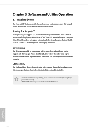
... If the Main Menu does not appear automatically, locate and double click on the file "ASRSETUP.EXE" in your system will be auto-detected and listed on a specific item then follow the order from top to bottom to install it. Therefore, the drivers you install can work properly. Running The Support CD To begin using the support CD, insert the CD into your CD-ROM drive.
... If the Main Menu does not appear automatically, locate and double click on the file "ASRSETUP.EXE" in your system will be auto-detected and listed on a specific item then follow the order from top to bottom to install it. Therefore, the drivers you install can work properly. Running The Support CD To begin using the support CD, insert the CD into your CD-ROM drive.

User Manual
Page 67
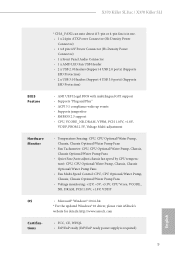
... some memory modules or power supplies. AMD fTPM Switch Use this item to enable or disable AMD CPU fTPM. If you install Windows® OS and want to enable this function, please set this to [Enabled]. Please set to [Disable] if above issue occurs. SVM Mode When this option is [Enabled]. 61 English Configuration options: [Enabled] and [Disabled]. The default value is [Enabled]. The default value is set this item to enable or disable AMD's Cool 'n' QuietTM technology. 4.4.1 CPU Configuration X370 Killer SLI/ac / X370 Killer SLI Cool 'n' Quiet Use this...
... some memory modules or power supplies. AMD fTPM Switch Use this item to enable or disable AMD CPU fTPM. If you install Windows® OS and want to enable this function, please set this to [Enabled]. Please set to [Disable] if above issue occurs. SVM Mode When this option is [Enabled]. 61 English Configuration options: [Enabled] and [Disabled]. The default value is [Enabled]. The default value is set this item to enable or disable AMD's Cool 'n' QuietTM technology. 4.4.1 CPU Configuration X370 Killer SLI/ac / X370 Killer SLI Cool 'n' Quiet Use this...
User Manual
Page 75
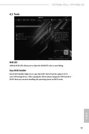
4.5 Tools X370 Killer SLI/ac / X370 Killer SLI RGB LED ASRock RGB LED allows you can start installing the operating system in RAID mode. After copying the drivers please change the SATA mode to RAID, then you to adjust the RGB LED color to your liking. English 69 Easy RAID Installer Easy RAID Installer helps you to copy the RAID driver from the support CD to your USB storage device.
4.5 Tools X370 Killer SLI/ac / X370 Killer SLI RGB LED ASRock RGB LED allows you can start installing the operating system in RAID mode. After copying the drivers please change the SATA mode to RAID, then you to adjust the RGB LED color to your liking. English 69 Easy RAID Installer Easy RAID Installer helps you to copy the RAID driver from the support CD to your USB storage device.
User Manual
Page 76
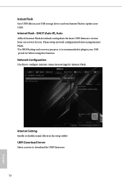
...*For BIOS backup and recovery purpose, it is recommended to plug in your USB pen drive before using this to configure internet connection settings for you. Internet Setting Enable or disable sound effects in the setup utility. Network Configuration Use this function. Internet Flash - DHCP (Auto IP), Auto ASRock Internet Flash downloads and updates the latest UEFI firmware version from our servers for Internet Flash. UEFI Download Server Select a server to update your UEFI. Instant Flash Save UEFI files in your USB storage device and run Instant Flash to download the UEFI firmware...
...*For BIOS backup and recovery purpose, it is recommended to plug in your USB pen drive before using this to configure internet connection settings for you. Internet Setting Enable or disable sound effects in the setup utility. Network Configuration Use this function. Internet Flash - DHCP (Auto IP), Auto ASRock Internet Flash downloads and updates the latest UEFI firmware version from our servers for Internet Flash. UEFI Download Server Select a server to update your UEFI. Instant Flash Save UEFI files in your USB storage device and run Instant Flash to download the UEFI firmware...

Quick Installation Guide
Page 4
... Fan Connector (CPU_FAN1) 3 CPU Fan / Waterpump Fan Connector (CPU_OPT/W_PUMP) 4 2 x 288-pin DDR4 DIMM Slots (DDR4_A1, DDR4_B1) 5 2 x 288-pin DDR4 DIMM Slots (DDR4_A2, DDR4_B2) 6 ATX Power Connector (ATXPWR1) 7 USB 3.0 Header (USB3_9_10) 8 USB 3.0 Header (USB3_7_8) 9 AMD LED Fan USB Header (USB_5) 10 AMD Fan LED Header (AMD_FAN_LED1) 11 Chassis Fan Connector (CHA_FAN1) 12 SATA3 Connectors (SATA3_5_6) 13 SATA3 Connectors (SATA3_3_4) 14 SATA3 Connectors (SATA3_1_2) 15 System Panel Header (PANEL1) 16 RGB LED Header (RGB_LED1) 17 RGB LED Header (RGB_LED2) 18 Clear CMOS Jumper (CLRMOS1) 19 Chassis...
... Fan Connector (CPU_FAN1) 3 CPU Fan / Waterpump Fan Connector (CPU_OPT/W_PUMP) 4 2 x 288-pin DDR4 DIMM Slots (DDR4_A1, DDR4_B1) 5 2 x 288-pin DDR4 DIMM Slots (DDR4_A2, DDR4_B2) 6 ATX Power Connector (ATXPWR1) 7 USB 3.0 Header (USB3_9_10) 8 USB 3.0 Header (USB3_7_8) 9 AMD LED Fan USB Header (USB_5) 10 AMD Fan LED Header (AMD_FAN_LED1) 11 Chassis Fan Connector (CHA_FAN1) 12 SATA3 Connectors (SATA3_5_6) 13 SATA3 Connectors (SATA3_3_4) 14 SATA3 Connectors (SATA3_1_2) 15 System Panel Header (PANEL1) 16 RGB LED Header (RGB_LED1) 17 RGB LED Header (RGB_LED2) 18 Clear CMOS Jumper (CLRMOS1) 19 Chassis...

Quick Installation Guide
Page 7
... X370 Killer SLI/ac / X370 Killer SLI Motherboard (ATX Form Factor) • ASRock X370 Killer SLI/ac / X370 Killer SLI Quick Installation Guide • ASRock X370 Killer SLI/ac / X370 Killer SLI Support CD • 1 x I/O Panel Shield • 4 x Serial ATA (SATA) Data Cables (Optional) • 1 x ASRock SLI_HB_Bridge_2S Card (Optional) • 3 x Screws for M.2 Socket (Optional) (for X370 Killer SLI only) • 2 x Screws for M.2 Socket (Optional) (for X370 Killer SLI/ac only) • 2 x ASRock WiFi 2.4/5 GHz Antennas (Optional) (for specific information about the model you are using...
... X370 Killer SLI/ac / X370 Killer SLI Motherboard (ATX Form Factor) • ASRock X370 Killer SLI/ac / X370 Killer SLI Quick Installation Guide • ASRock X370 Killer SLI/ac / X370 Killer SLI Support CD • 1 x I/O Panel Shield • 4 x Serial ATA (SATA) Data Cables (Optional) • 1 x ASRock SLI_HB_Bridge_2S Card (Optional) • 3 x Screws for M.2 Socket (Optional) (for X370 Killer SLI only) • 2 x Screws for M.2 Socket (Optional) (for X370 Killer SLI/ac only) • 2 x ASRock WiFi 2.4/5 GHz Antennas (Optional) (for specific information about the model you are using...
Quick Installation Guide
Page 11
X370 Killer SLI/ac / X370 Killer SLI * CHA_FAN2 can auto detect if 3-pin or 4-pin fan is in use. • 1 x 24 pin ATX Power Connector (Hi-Density Power Connector) • 1 x 8 pin 12V Power Connector (Hi-Density Power Connector) • 1 x Front Panel Audio Connector • 1 x AMD LED Fan USB Header • 2 x USB 2.0 Headers (Support 4 USB 2.0 ports) (Supports ESD Protection) • 2 x USB 3.0 Headers (Support 4 USB 3.0 ports) (Supports ESD Protection) BIOS Feature • AMI UEFI Legal BIOS with multilingual GUI support • Supports "Plug and Play" • ACPI 5.1 ...
X370 Killer SLI/ac / X370 Killer SLI * CHA_FAN2 can auto detect if 3-pin or 4-pin fan is in use. • 1 x 24 pin ATX Power Connector (Hi-Density Power Connector) • 1 x 8 pin 12V Power Connector (Hi-Density Power Connector) • 1 x Front Panel Audio Connector • 1 x AMD LED Fan USB Header • 2 x USB 2.0 Headers (Support 4 USB 2.0 ports) (Supports ESD Protection) • 2 x USB 3.0 Headers (Support 4 USB 3.0 ports) (Supports ESD Protection) BIOS Feature • AMI UEFI Legal BIOS with multilingual GUI support • Supports "Plug and Play" • ACPI 5.1 ...

Quick Installation Guide
Page 32
... chassis power LED and the chassis speaker to 6.0 Gb/s data transfer rate. P+ USB_PWR This header is used for internal storage devices with up to this motherboard. English 30 Each USB 2.0 header can support two ports. USB 2.0 Headers ((9-pin USB_1_2) (see p.1, No. 21) (9-pin USB_3_4) (see p.1, No. 22) USB_PWR PP+ GND DUMMY 1 GND P+ PUSB_PWR There are two headers on the AMD SR3 Heatsink. SATA3_6 SATA3_5 These six SATA3 connectors support SATA data cables for connecting the USB connector on this header...
... chassis power LED and the chassis speaker to 6.0 Gb/s data transfer rate. P+ USB_PWR This header is used for internal storage devices with up to this motherboard. English 30 Each USB 2.0 header can support two ports. USB 2.0 Headers ((9-pin USB_1_2) (see p.1, No. 21) (9-pin USB_3_4) (see p.1, No. 22) USB_PWR PP+ GND DUMMY 1 GND P+ PUSB_PWR There are two headers on the AMD SR3 Heatsink. SATA3_6 SATA3_5 These six SATA3 connectors support SATA data cables for connecting the USB connector on this header...
Quick Installation Guide
Page 127
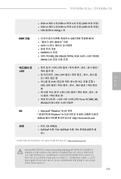
X370 Killer SLI/ac / X370 Killer SLI 한국어 • USB 2.0 헤더 2 개 (USB 2.0 포트 4 ESD USB 3.0 헤더 2 개 (USB 3.0 포트 4 ESD LED 탑재 Dr. Debug 1 개 BIOS 기능 GUI AMI UEFI 적합형 BIOS ACPI 5.1 SMBIOS 2.3 지원 • CPU, VCORE_NB, DRAM, VPPM, PCH 1.05V, +1.8V, VDDP, PROM 2.5V CPU, CPU CPU, CPU CPU CPU, CPU CPU, CPU 12V, +5V, +3.3V, CPU Vcore, VCORE_NB, DRAM, PCH 1.05V, +1.8V, VDDP OS...
X370 Killer SLI/ac / X370 Killer SLI 한국어 • USB 2.0 헤더 2 개 (USB 2.0 포트 4 ESD USB 3.0 헤더 2 개 (USB 3.0 포트 4 ESD LED 탑재 Dr. Debug 1 개 BIOS 기능 GUI AMI UEFI 적합형 BIOS ACPI 5.1 SMBIOS 2.3 지원 • CPU, VCORE_NB, DRAM, VPPM, PCH 1.05V, +1.8V, VDDP, PROM 2.5V CPU, CPU CPU, CPU CPU CPU, CPU CPU, CPU 12V, +5V, +3.3V, CPU Vcore, VCORE_NB, DRAM, PCH 1.05V, +1.8V, VDDP OS...

RAID Installation Guide
Page 5
... to enter UEFI setup utility. D. STEP 2: Create and configure the RAID disk A. B. E. B. During system boot, press to enter UEFI setup utility. During system boot, press or key to enter legacy RAID ROM utility. Please select the correct driver for Windows® 8 64-bit / 8.1 64-bit / 10 64-bit only) 5 For RAID disk size larger than 2TB, please refer to Way 2 (UEFI Mode for AMD A85X, A75, A55 chipsets Way 1: Use legacy RAID ROM to 2TB. Plug a USB drive into one of the SATA ports 5 ~ 8 which the size of the USB port. Insert the Support...
... to enter UEFI setup utility. D. STEP 2: Create and configure the RAID disk A. B. E. B. During system boot, press to enter UEFI setup utility. During system boot, press or key to enter legacy RAID ROM utility. Please select the correct driver for Windows® 8 64-bit / 8.1 64-bit / 10 64-bit only) 5 For RAID disk size larger than 2TB, please refer to Way 2 (UEFI Mode for AMD A85X, A75, A55 chipsets Way 1: Use legacy RAID ROM to 2TB. Plug a USB drive into one of the SATA ports 5 ~ 8 which the size of the USB port. Insert the Support...

RAID Installation Guide
Page 9
... RAID disk will show up UEFI A. C. Click to save to enter legacy RAID ROM utility. Please install the DVD-ROM into one of the SATA ports 5 ~ 8 which the size of the RAID disk is under /I386 directory. After copying RAID driver to a USB flash drive, please set the "SATA Mode" option to in MBR mode which support IDE Combined Mode. *Due to the AMD A68H chipset limitation, please install the DVD-ROM into one of the SATA ports 1 ~ 4 and set the "SATA Mode" option back to in GPT mode to a USB flash drive A. E. STEP 4: Windows installation...
... RAID disk will show up UEFI A. C. Click to save to enter legacy RAID ROM utility. Please install the DVD-ROM into one of the SATA ports 5 ~ 8 which the size of the RAID disk is under /I386 directory. After copying RAID driver to a USB flash drive, please set the "SATA Mode" option to in MBR mode which support IDE Combined Mode. *Due to the AMD A68H chipset limitation, please install the DVD-ROM into one of the SATA ports 1 ~ 4 and set the "SATA Mode" option back to in GPT mode to a USB flash drive A. E. STEP 4: Windows installation...
RAID Installation Guide
Page 18
... on your system. 2.2 Browser Support On the Host PC with AMD SATA RAID controllers. Insert the software CD into your networked PC in folder _jvm under the same directory where RAIDXpert is designed to configure RAID functions by using RAIDXpert RAID management software under Windows environment. Double-click the Installer icon to all AMD SATA logical drives that may be present on a network. Its browser-based GUI provides...
... on your system. 2.2 Browser Support On the Host PC with AMD SATA RAID controllers. Insert the software CD into your networked PC in folder _jvm under the same directory where RAIDXpert is designed to configure RAID functions by using RAIDXpert RAID management software under Windows environment. Double-click the Installer icon to all AMD SATA logical drives that may be present on a network. Its browser-based GUI provides...


