
User Manual
Page 3
...1 1.2 Specifications 2 1.3 Motherboard Layout 7 1.4 I/O Panel 10 1.5 Block Diagram 12 1.6 802.11ax Wi-Fi 6E Module and ASRock WiFi 2.4/5/6 GHz Antenna 13 Chapter 2 Installation 14 2.1 Installing the CPU 15 2.2 Installing the CPU Liquid Cooler 19 2.3 Installing Memory Modules (DIMM) 21 2.4 Connecting the Front Panel Header 23 2.5 Installing the Motherboard 24 2.6 Installing SATA Drives 25 2.7 Installing a Graphics Card 27 2.8 Connecting Peripheral Devices 29 2.9 Connecting the Power Connectors 30 2.10 Power On 31 2.11 Jumpers Setup 32 2.12 Onboard Headers and...
...1 1.2 Specifications 2 1.3 Motherboard Layout 7 1.4 I/O Panel 10 1.5 Block Diagram 12 1.6 802.11ax Wi-Fi 6E Module and ASRock WiFi 2.4/5/6 GHz Antenna 13 Chapter 2 Installation 14 2.1 Installing the CPU 15 2.2 Installing the CPU Liquid Cooler 19 2.3 Installing Memory Modules (DIMM) 21 2.4 Connecting the Front Panel Header 23 2.5 Installing the Motherboard 24 2.6 Installing SATA Drives 25 2.7 Installing a Graphics Card 27 2.8 Connecting Peripheral Devices 29 2.9 Connecting the Power Connectors 30 2.10 Power On 31 2.11 Jumpers Setup 32 2.12 Onboard Headers and...
User Manual
Page 5
... Factor) • ASRock TRX50 WS User Manual • 4 x Serial ATA (SATA) Data Cables (Optional) • 1 x ASRock WiFi 2.4/5/6 GHz Antenna (Optional) • 2 x Thermistor Cables (Optional) • 1 x Multi PSU Adaptor Cable (Optional) • 2 x Screws for M.2 Sockets (Optional) • 2 x Standoffs for purchasing ASRock TRX50 WS motherboard, a reliable motherboard produced under ASRock's consistently stringent quality control. Because the motherboard specifications and the BIOS software might be updated, the content of this documentation will be subject to change without further...
... Factor) • ASRock TRX50 WS User Manual • 4 x Serial ATA (SATA) Data Cables (Optional) • 1 x ASRock WiFi 2.4/5/6 GHz Antenna (Optional) • 2 x Thermistor Cables (Optional) • 1 x Multi PSU Adaptor Cable (Optional) • 2 x Screws for M.2 Sockets (Optional) • 2 x Standoffs for purchasing ASRock TRX50 WS motherboard, a reliable motherboard produced under ASRock's consistently stringent quality control. Because the motherboard specifications and the BIOS software might be updated, the content of this documentation will be subject to change without further...

User Manual
Page 6
... mode* Chipset: • 1 x M.2 Socket (Key E), supports type 2230 WiFi/BT PCIe WiFi module * Supports NVMe SSD as boot disks • 15μ Gold Contact in VGA PCIe Slots Audio • 7.1 CH HD Audio with Content Protection (Realtek ALC1220 Audio Codec) • Impedance Sensing on Rear Out port • Individual PCB Layers for R/L Audio Channel • Nahimic Audio 2 PCIE4 at x16; capacity of system memory: 1TB * Please refer to 7600+(OC)* • Max...
... mode* Chipset: • 1 x M.2 Socket (Key E), supports type 2230 WiFi/BT PCIe WiFi module * Supports NVMe SSD as boot disks • 15μ Gold Contact in VGA PCIe Slots Audio • 7.1 CH HD Audio with Content Protection (Realtek ALC1220 Audio Codec) • Impedance Sensing on Rear Out port • Individual PCB Layers for R/L Audio Channel • Nahimic Audio 2 PCIE4 at x16; capacity of system memory: 1TB * Please refer to 7600+(OC)* • Max...
User Manual
Page 7
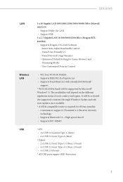
...diversity technology • Supports Bluetooth 5.2 + High speed class II • Supports MU-MIMO CPU: • 1 x USB 3.2 Gen2x2 Type-C (Rear) • 4 x USB 3.2 Gen2 Type-A (Rear) Chipset: • 2 x USB 3.2 Gen2 Type-C (1 Rear, 1 Front) • 4 x USB 3.2 Gen1 Type-A (2 Rear, 2 Front) • 4 x USB 2.0 (Front) * All USB ports support ESD Protection 3 Smart Auto Adjust Bandwidth Control - Visual Network Usage Statistics - TRX50 WS LAN Wireless LAN USB 1 x 10 Gigabit LAN 100/1000/2500/5000/10000 Mb/s (Marvell AQC113) • Support Wake-On-LAN • Support PXE 1 x 2.5 Gigabit LAN...
...diversity technology • Supports Bluetooth 5.2 + High speed class II • Supports MU-MIMO CPU: • 1 x USB 3.2 Gen2x2 Type-C (Rear) • 4 x USB 3.2 Gen2 Type-A (Rear) Chipset: • 2 x USB 3.2 Gen2 Type-C (1 Rear, 1 Front) • 4 x USB 3.2 Gen1 Type-A (2 Rear, 2 Front) • 4 x USB 2.0 (Front) * All USB ports support ESD Protection 3 Smart Auto Adjust Bandwidth Control - Visual Network Usage Statistics - TRX50 WS LAN Wireless LAN USB 1 x 10 Gigabit LAN 100/1000/2500/5000/10000 Mb/s (Marvell AQC113) • Support Wake-On-LAN • Support PXE 1 x 2.5 Gigabit LAN...

User Manual
Page 8
... M.2 Socket (M2_2, Key M), supports type 2260/2280 PCIe Gen4x4 (64 Gb/s) mode* • 4 x SATA3 6.0 Gb/s Connectors * Supports NVMe SSD as boot disks RAID • Supports RAID 0, RAID 1 and RAID 10 for SATA storage devices • Supports RAID 0, RAID 1 and RAID 10 for M.2 NVMe storage devices* * Requires additional M.2 NVMe expansion cards to support RAID 10 Connector • 2 x Thermistor Cable Headers • 1 x SPI TPM Header • 1 x COM Port Header • 1 x Chassis Intrusion and Speaker Header • 2 x Addressable LED Headers* • 1 x CPU Fan Connector (4-pin)** 4
... M.2 Socket (M2_2, Key M), supports type 2260/2280 PCIe Gen4x4 (64 Gb/s) mode* • 4 x SATA3 6.0 Gb/s Connectors * Supports NVMe SSD as boot disks RAID • Supports RAID 0, RAID 1 and RAID 10 for SATA storage devices • Supports RAID 0, RAID 1 and RAID 10 for M.2 NVMe storage devices* * Requires additional M.2 NVMe expansion cards to support RAID 10 Connector • 2 x Thermistor Cable Headers • 1 x SPI TPM Header • 1 x COM Port Header • 1 x Chassis Intrusion and Speaker Header • 2 x Addressable LED Headers* • 1 x CPU Fan Connector (4-pin)** 4
User Manual
Page 9
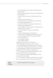
...1 x 3 pin ATX Power Connector***** • 2 x 8 pin ATX 12V Power Connectors (Hi-Density Power Connector) (for Motherboard)****** • 2 x 6 pin PCIe 12V Power Connectors (Hi-Density Power Connector) (for Motherboard)****** • 1 x 6 pin Graphics 12V Power Connector (Hi-Density Power Connector) (for PCIe card 1 x Front Panel Audio Connector (15μ Gold Audio Connector) • 2 x USB 2.0 Headers (Support 4 USB 2.0 ports) • 1 x USB 3.2 Gen1 Header (Supports 2 USB 3.2 Gen1 ports) • 1 x Front Panel Type C USB 3.2 Gen2 Header (10 Gb/s) • 1 x Dr. Debug with LED •...
...1 x 3 pin ATX Power Connector***** • 2 x 8 pin ATX 12V Power Connectors (Hi-Density Power Connector) (for Motherboard)****** • 2 x 6 pin PCIe 12V Power Connectors (Hi-Density Power Connector) (for Motherboard)****** • 1 x 6 pin Graphics 12V Power Connector (Hi-Density Power Connector) (for PCIe card 1 x Front Panel Audio Connector (15μ Gold Audio Connector) • 2 x USB 2.0 Headers (Support 4 USB 2.0 ports) • 1 x USB 3.2 Gen1 Header (Supports 2 USB 3.2 Gen1 ports) • 1 x Front Panel Type C USB 3.2 Gen2 Header (10 Gb/s) • 1 x Dr. Debug with LED •...

User Manual
Page 11
USB 3.2 Gen1: USB32_4 USB 3.2 Gen1: USB32_3 USB 3.2 Gen2: USB32_2 USB 3.2 Gen2: USB32_1 1.3 Motherboard Layout TRX50 WS 12 3 4 56 789 M2_WIFI_1 CLRC BIOS MOS _FB ATX12V2 PCIE12V2_6P CHA_FAN2 /WP 1 TPM_BIOS_PH1 Reset Power 1 CPU_FAN2 CPU_FAN1 ADDR_LED2 /WP BIOS ROM Dr. Debug DDR5_G0 (64 bit, 288-pin module) DDR5_E0(64 bit, 288-pin module) ATX12V1 PCIE12V1_6P 10 11 12 ATXPWR1 USB 3.2 Gen2 USB32_5 USB 3.2 Gen2 USB32_TC1 USB 3.2 Gen2 USB32_6 USB 3.2 Gen2x2 USB32_TC2 Top: 2.5GLAN (Dragon...
USB 3.2 Gen1: USB32_4 USB 3.2 Gen1: USB32_3 USB 3.2 Gen2: USB32_2 USB 3.2 Gen2: USB32_1 1.3 Motherboard Layout TRX50 WS 12 3 4 56 789 M2_WIFI_1 CLRC BIOS MOS _FB ATX12V2 PCIE12V2_6P CHA_FAN2 /WP 1 TPM_BIOS_PH1 Reset Power 1 CPU_FAN2 CPU_FAN1 ADDR_LED2 /WP BIOS ROM Dr. Debug DDR5_G0 (64 bit, 288-pin module) DDR5_E0(64 bit, 288-pin module) ATX12V1 PCIE12V1_6P 10 11 12 ATXPWR1 USB 3.2 Gen2 USB32_5 USB 3.2 Gen2 USB32_TC1 USB 3.2 Gen2 USB32_6 USB 3.2 Gen2x2 USB32_TC2 Top: 2.5GLAN (Dragon...

User Manual
Page 12
... Connector (SLIM1) 20 SATA3 Connectors (SATA3_2)(Upper), (SATA3_1)(Lower) 21 SATA3 Connectors (SATA3_4)(Upper), (SATA3_3)(Lower) 22 6 pin Graphics 12V Power Connector (GFX_12V1) 23 Chassis/Water Pump Fan Connector (CHA_FAN3/WP) 24 System Panel Header (PANEL1) 25 Chassis Intrusion and Speaker Header (SPK_CI1) 26 Thermistor Cable Header (T_SENSOR1) 27 Thermistor Cable Header (T_SENSOR2) 28 USB 2.0 Header (USB_3_4) 29 USB 2.0 Header (USB_1_2) 30 USB 3.2 Gen1 Header (USB32_7_8) 31 Clear CMOS Jumper (CLRCMOS1) 32 Chassis/Water Pump Fan Connector (CHA_FAN1/WP) 33 Addressable LED Header...
... Connector (SLIM1) 20 SATA3 Connectors (SATA3_2)(Upper), (SATA3_1)(Lower) 21 SATA3 Connectors (SATA3_4)(Upper), (SATA3_3)(Lower) 22 6 pin Graphics 12V Power Connector (GFX_12V1) 23 Chassis/Water Pump Fan Connector (CHA_FAN3/WP) 24 System Panel Header (PANEL1) 25 Chassis Intrusion and Speaker Header (SPK_CI1) 26 Thermistor Cable Header (T_SENSOR1) 27 Thermistor Cable Header (T_SENSOR2) 28 USB 2.0 Header (USB_3_4) 29 USB 2.0 Header (USB_1_2) 30 USB 3.2 Gen1 Header (USB32_7_8) 31 Clear CMOS Jumper (CLRCMOS1) 32 Chassis/Water Pump Fan Connector (CHA_FAN1/WP) 33 Addressable LED Header...
User Manual
Page 17
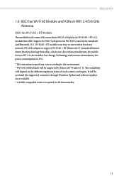
... be supported by Microsoft® Windows® 11. TRX50 WS 1.6 802.11ax Wi-Fi 6E Module and ASRock WiFi 2.4/5/6 GHz Antenna 802.11ax Wi-Fi 6E + BT Module This motherboard comes ...supported countries) through Windows Update and software updates once available. * A 6GHz compatible router is an easy-to-use wireless local area network (WLAN) adapter to the environment. * Wi-Fi 6E (6GHz band) will depend on the different regulation status of functionality into the mobile devices. Bluetooth v5.2 standard features Smart Ready technology that offers support for PCs. * The transmission speed...
... be supported by Microsoft® Windows® 11. TRX50 WS 1.6 802.11ax Wi-Fi 6E Module and ASRock WiFi 2.4/5/6 GHz Antenna 802.11ax Wi-Fi 6E + BT Module This motherboard comes ...supported countries) through Windows Update and software updates once available. * A 6GHz compatible router is an easy-to-use wireless local area network (WLAN) adapter to the environment. * Wi-Fi 6E (6GHz band) will depend on the different regulation status of functionality into the mobile devices. Bluetooth v5.2 standard features Smart Ready technology that offers support for PCs. * The transmission speed...
User Manual
Page 25
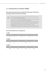
... are installed, then Triple Channel Memory Technology is not allowed to install a DDR, DDR2 , DDR3 or DDR4 memory module into the slot at incorrect orientation. If three memory modules are installed in one correct orientation. TRX50 WS 2.3 Installing Memory Modules (DIMM) This motherboard provides four 288-pin DDR5 (Double Data Rate 5) DIMM slots, and supports Quad Channel Memory Technology. 1. It will cause permanent damage to install identical (the same brand, speed, size and chip-type...
... are installed, then Triple Channel Memory Technology is not allowed to install a DDR, DDR2 , DDR3 or DDR4 memory module into the slot at incorrect orientation. If three memory modules are installed in one correct orientation. TRX50 WS 2.3 Installing Memory Modules (DIMM) This motherboard provides four 288-pin DDR5 (Double Data Rate 5) DIMM slots, and supports Quad Channel Memory Technology. 1. It will cause permanent damage to install identical (the same brand, speed, size and chip-type...

User Manual
Page 32
... (PCIe 4.0 x16 slot) is used for PCIe x8 lane width graphics cards. *If you start the installation. PCIe slots: PCIE1 (PCIe 5.0 x16 slot) is used for the card before you want to install a dual slot graphics card, install it to the motherboard's chassis fan connector (CHA_FAN1~3/WP) when using multiple graphics cards. 28 Before installing an expansion card, please make necessary hardware settings for PCIe x8 lane width graphics cards. Please read the documentation of the expansion card and make sure that the power supply is switched...
... (PCIe 4.0 x16 slot) is used for PCIe x8 lane width graphics cards. *If you start the installation. PCIe slots: PCIE1 (PCIe 5.0 x16 slot) is used for the card before you want to install a dual slot graphics card, install it to the motherboard's chassis fan connector (CHA_FAN1~3/WP) when using multiple graphics cards. 28 Before installing an expansion card, please make necessary hardware settings for PCIe x8 lane width graphics cards. Please read the documentation of the expansion card and make sure that the power supply is switched...

User Manual
Page 37
... configure the way to turn off (S5). Placing jumper caps over these headers and connectors. You may differ by chassis. The LED keeps blinking when the system is in S1/S3 sleep state. Note the positive and negative pins before connecting the cables. TRX50 WS 2.12 Onboard Headers and Connectors Onboard headers and connectors are matched correctly. 33 A front panel module mainly consists of power button, reset button, power LED, hard drive activity LED, speaker and etc. PLED (System Power LED): Connect to the reset button...
... configure the way to turn off (S5). Placing jumper caps over these headers and connectors. You may differ by chassis. The LED keeps blinking when the system is in S1/S3 sleep state. Note the positive and negative pins before connecting the cables. TRX50 WS 2.12 Onboard Headers and Connectors Onboard headers and connectors are matched correctly. 33 A front panel module mainly consists of power button, reset button, power LED, hard drive activity LED, speaker and etc. PLED (System Power LED): Connect to the reset button...

User Manual
Page 50
... 8 pin and 6 pin 12V Power Connectors when overclocking. *Warning: Please make sure that the power cable connected is required to ATX12V1 or ATX12V2. ATX12V1 4 8 1 5 ATX12V2 8 5 4 1 46 To use a 4-pin ATX power supply, please plug it along Pin 1 and Pin 5. * It is for the CPU and not the graphics card. Do not plug the PCIe 6-pin power cable to connect both ATX12V1 and ATX12V2; 8 pin ATX 12V Power Connectors (8-pin ATX12V1) (see p.7, No. 11) (8-pin ATX12V2) (see p.7, No. 1) This motherboard provides two 8-pin ATX 12V power connectors.
... 8 pin and 6 pin 12V Power Connectors when overclocking. *Warning: Please make sure that the power cable connected is required to ATX12V1 or ATX12V2. ATX12V1 4 8 1 5 ATX12V2 8 5 4 1 46 To use a 4-pin ATX power supply, please plug it along Pin 1 and Pin 5. * It is for the CPU and not the graphics card. Do not plug the PCIe 6-pin power cable to connect both ATX12V1 and ATX12V2; 8 pin ATX 12V Power Connectors (8-pin ATX12V1) (see p.7, No. 11) (8-pin ATX12V2) (see p.7, No. 1) This motherboard provides two 8-pin ATX 12V power connectors.

User Manual
Page 57
TRX50 WS 2.13 Smart Buttons The motherboard has four smart buttons: Power Button, Reset Button, Clear CMOS Button and BIOS Flashback Button, allowing users to quickly turn on /off the system. PWRBTN1 Reset Button (RSTBTN1) (see p.7, No. 6) Power Button allows users to quickly reset the system. RSTBTN1 Reset 53 Power Button (PWRBTN1) (see p.7, No. 5) Reset Button allows users to quickly turn on /off the system, reset the system, clear the CMOS values or flash the BIOS.
TRX50 WS 2.13 Smart Buttons The motherboard has four smart buttons: Power Button, Reset Button, Clear CMOS Button and BIOS Flashback Button, allowing users to quickly turn on /off the system. PWRBTN1 Reset Button (RSTBTN1) (see p.7, No. 6) Power Button allows users to quickly reset the system. RSTBTN1 Reset 53 Power Button (PWRBTN1) (see p.7, No. 5) Reset Button allows users to quickly turn on /off the system, reset the system, clear the CMOS values or flash the BIOS.

User Manual
Page 60
... the power supply's AC switch. *There is active, the data will stay encrypted and the system will not boot into the operating system. Rename the file to "creative.rom" and save it to the motherboard. Please make sure the file system of X: USB flash drive. 5. ASRock BIOS Flashback feature allows you to update BIOS without CPU. Download the latest BIOS file from the motherboard for about three seconds. Plug the 24 pin power connector...
... the power supply's AC switch. *There is active, the data will stay encrypted and the system will not boot into the operating system. Rename the file to "creative.rom" and save it to the motherboard. Please make sure the file system of X: USB flash drive. 5. ASRock BIOS Flashback feature allows you to update BIOS without CPU. Download the latest BIOS file from the motherboard for about three seconds. Plug the 24 pin power connector...
User Manual
Page 67
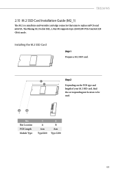
B A No. Nut Location PCB Length Module Type 1 A 6cm Type2260 2 B 8cm Type 2280 63 Step 2 2 1 Depending on the PCB type and length of your M.2 SSD card, find the corresponding nut location to replace mPCIe and mSATA. TRX50 WS 2.15 M.2 SSD Card Installation Guide (M2_1) The M.2 is a small size and versatile card edge connector that aims to be used. Installing the M.2 SSD Card Step 1 Prepare a M.2 SSD card. The Blazing M.2 Socket (M2_1, Key M) supports type 2260/2280 PCIe Gen5x4 (128 Gb/s) mode.
B A No. Nut Location PCB Length Module Type 1 A 6cm Type2260 2 B 8cm Type 2280 63 Step 2 2 1 Depending on the PCB type and length of your M.2 SSD card, find the corresponding nut location to replace mPCIe and mSATA. TRX50 WS 2.15 M.2 SSD Card Installation Guide (M2_1) The M.2 is a small size and versatile card edge connector that aims to be used. Installing the M.2 SSD Card Step 1 Prepare a M.2 SSD card. The Blazing M.2 Socket (M2_1, Key M) supports type 2260/2280 PCIe Gen5x4 (128 Gb/s) mode.
User Manual
Page 70
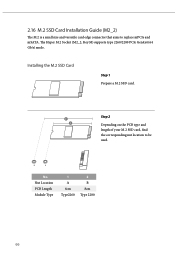
Step 2 2 1 Depending on the PCB type and length of your M.2 SSD card, find the corresponding nut location to replace mPCIe and mSATA. 2.16 M.2 SSD Card Installation Guide (M2_2) The M.2 is a small size and versatile card edge connector that aims to be used. B A No. The Hyper M.2 Socket (M2_2, Key M) supports type 2260/2280 PCIe Gen4x4 (64 Gb/s) mode. Nut Location PCB Length Module Type 1 A 6cm Type2260 2 B 8cm Type 2280 66 Installing the M.2 SSD Card Step 1 Prepare a M.2 SSD card.
Step 2 2 1 Depending on the PCB type and length of your M.2 SSD card, find the corresponding nut location to replace mPCIe and mSATA. 2.16 M.2 SSD Card Installation Guide (M2_2) The M.2 is a small size and versatile card edge connector that aims to be used. B A No. The Hyper M.2 Socket (M2_2, Key M) supports type 2260/2280 PCIe Gen4x4 (64 Gb/s) mode. Nut Location PCB Length Module Type 1 A 6cm Type2260 2 B 8cm Type 2280 66 Installing the M.2 SSD Card Step 1 Prepare a M.2 SSD card.

RAID Installation Guide
Page 2
... use the onboard RAID Option ROM Utility to configure RAID. 1.1 Introduction to read and write data in this documentation will see shall depend on RAID support. After you make a SATA driver diskette, press [F2] or [Del] to enter BIOS setup to set . The actual setup options you will be updated, the content of Independent Disks", which is a method combining two or more hard disk drives into one logical unit. Because the motherboard specifications and the BIOS software...
... use the onboard RAID Option ROM Utility to configure RAID. 1.1 Introduction to read and write data in this documentation will see shall depend on RAID support. After you make a SATA driver diskette, press [F2] or [Del] to enter BIOS setup to set . The actual setup options you will be updated, the content of Independent Disks", which is a method combining two or more hard disk drives into one logical unit. Because the motherboard specifications and the BIOS software...

RAID Installation Guide
Page 13
While the system is shown in this picture. If the system restarts at this point, then please open the boot menu that is booting, please press [F11] to delete or create any partition at this to boot from. STEP 3: Windows installation Insert the USB drive with Windows 11 installation files. It should list the USB drive as a UEFI device. When the disk selection page shows up during the Windows installation process, please click . Do not try to open the [F11] boot menu again. 1. Then restart the system. Please select this point. 13
While the system is shown in this picture. If the system restarts at this point, then please open the boot menu that is booting, please press [F11] to delete or create any partition at this to boot from. STEP 3: Windows installation Insert the USB drive with Windows 11 installation files. It should list the USB drive as a UEFI device. When the disk selection page shows up during the Windows installation process, please click . Do not try to open the [F11] boot menu again. 1. Then restart the system. Please select this point. 13

RAID Installation Guide
Page 19
You want to . 2. Enter the UEFI Setup Utility by pressing or right after you power on a 2.5" or 3.5" SATA SSD or HDD. You can use for the following scenarios: 1. AMD Windows RAID Installation Guide Caution: This chapter describes how to configure a RAID volume with 2.5" or 3.5" SATA SSDs or HDDs. 2.1 Create a RAID volume under Windows. Windows is installed on an NVMe M.2 SSD. You want to configure a RAID volume under Windows 1. Go to Boot menu and set "Boot Option #1" to configure a RAID volume with NVMe M.2 SSDs. 2. Windows is installed on the computer. 19 11.
You want to . 2. Enter the UEFI Setup Utility by pressing or right after you power on a 2.5" or 3.5" SATA SSD or HDD. You can use for the following scenarios: 1. AMD Windows RAID Installation Guide Caution: This chapter describes how to configure a RAID volume with 2.5" or 3.5" SATA SSDs or HDDs. 2.1 Create a RAID volume under Windows. Windows is installed on an NVMe M.2 SSD. You want to configure a RAID volume under Windows 1. Go to Boot menu and set "Boot Option #1" to configure a RAID volume with NVMe M.2 SSDs. 2. Windows is installed on the computer. 19 11.


