User Manual
Page 4
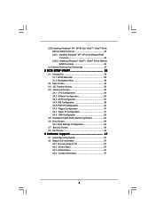
... 3.4 Advanced Screen 53 3.4.1 CPU Configuration 54 3.4.2 Chipset Configuration 56 3.4.3 ACPI Configuration 57 3.4.4 IDE Configuration 58 3.4.5 PCIPnP Configuration 60 3.4.6 Floppy Configuration 61 3.4.7 Super IO Configuration 61 3.4.8 USB Configuration 62 3.5 Hardware Health Event Monitoring Screen 63 3.6 Boot Screen 64 3.6.1 Boot Settings Configuration 64 3.7 Security Screen 65 3.8 Exit Screen 66 4 Software Support 67 4.1 Install...
... 3.4 Advanced Screen 53 3.4.1 CPU Configuration 54 3.4.2 Chipset Configuration 56 3.4.3 ACPI Configuration 57 3.4.4 IDE Configuration 58 3.4.5 PCIPnP Configuration 60 3.4.6 Floppy Configuration 61 3.4.7 Super IO Configuration 61 3.4.8 USB Configuration 62 3.5 Hardware Health Event Monitoring Screen 63 3.6 Boot Screen 64 3.6.1 Boot Settings Configuration 64 3.7 Security Screen 65 3.8 Exit Screen 66 4 Software Support 67 4.1 Install...
User Manual
Page 6
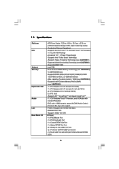
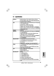
... - 1 x PS/2 Mouse Port - 1 x PS/2 Keyboard Port - 1 x Coaxial SPDIF Out Port - 1 x Optical SPDIF Out Port - 6 x Ready-to-Use USB 2.0 Ports - 2 x Powered eSATAII/USB Connectors - 1 x RJ-45 LAN Port with LED (ACT/LINK LED and SPEED LED) 6 Supports Intel® Turbo Boost Technology - Intel®...; P55 - Max. Supports Hyper-Threading Technology (see CAUTION 3) - 4 x DDR3 DIMM slots - Realtek RTL8111DL - ATX Form Factor: 12.0-in x 8.6-...
... - 1 x PS/2 Mouse Port - 1 x PS/2 Keyboard Port - 1 x Coaxial SPDIF Out Port - 1 x Optical SPDIF Out Port - 6 x Ready-to-Use USB 2.0 Ports - 2 x Powered eSATAII/USB Connectors - 1 x RJ-45 LAN Port with LED (ACT/LINK LED and SPEED LED) 6 Supports Intel® Turbo Boost Technology - Intel®...; P55 - Max. Supports Hyper-Threading Technology (see CAUTION 3) - 4 x DDR3 DIMM slots - Realtek RTL8111DL - ATX Form Factor: 12.0-in x 8.6-...
User Manual
Page 7
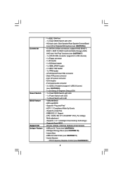
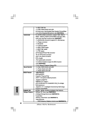
...T. (Intelligent Overclocking Technology) - ASRock OC Tuner (see CAUTION 10) - Hybrid Booster: - Supports "Plug and Play" - O. Supports Smart BIOS - Instant Boot - ASRock Instant Flash (see CAUTION 7) -... 1 x ATA133 IDE connector (supports 2 x IDE devices) - 1 x Floppy connector - 1 x IR header - 1 x COM port header - 1 x HDMI_SPDIF header - 1 x IEEE 1394 header - 1 x TPM header - HD Audio Jack: Side Speaker/Rear Speaker/Central/Bass/ Line in header - Supports jumperfree - Front panel audio connector - 3 x USB 2.0 headers (support 6 USB...
...T. (Intelligent Overclocking Technology) - ASRock OC Tuner (see CAUTION 10) - Hybrid Booster: - Supports "Plug and Play" - O. Supports Smart BIOS - Instant Boot - ASRock Instant Flash (see CAUTION 7) -... 1 x ATA133 IDE connector (supports 2 x IDE devices) - 1 x Floppy connector - 1 x IR header - 1 x COM port header - 1 x HDMI_SPDIF header - 1 x IEEE 1394 header - 1 x TPM header - HD Audio Jack: Side Speaker/Rear Speaker/Central/Bass/ Line in header - Supports jumperfree - Front panel audio connector - 3 x USB 2.0 headers (support 6 USB...
User Manual
Page 9
...stands for Energy Using Product, was a provision regulated by hardware monitor function and overclock your USB flash drive, floppy disk or hard drive, then you to access ASRock Instant Flash. Featuring an advanced proprietary hardware and software design, Intelligent Energy Saver is higher ...total AC power of Intelligent Energy Saver. Combo Cooler Option (C.C.O.) provides the flexible option to define the power consumption for USB 2.0 works fine under Windows® environment. According to provide exceptional power saving and improve power efficiency without entering operating ...
...stands for Energy Using Product, was a provision regulated by hardware monitor function and overclock your USB flash drive, floppy disk or hard drive, then you to access ASRock Instant Flash. Featuring an advanced proprietary hardware and software design, Intelligent Energy Saver is higher ...total AC power of Intelligent Energy Saver. Combo Cooler Option (C.C.O.) provides the flexible option to define the power consumption for USB 2.0 works fine under Windows® environment. According to provide exceptional power saving and improve power efficiency without entering operating ...

User Manual
Page 11
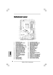
... 38 37 USB 2.0 T: USB0 B: USB1 USB 2.0 T: USB2 B: USB3 Top: IEEE 1394 USB 2.0 T: USB4 B: USB5 Top: RJ-45 Top: SIDE SPK Center: REAR SPK FRONT Bottom: CTR BASS MIC IN Top: LINE IN Center: Bottom: 36 LAN PHY 35 PWR_FAN1 CPU_FAN1 1394a CrossFireX PCIE1 P55 Pro EuP Ready PCI... Express 2.0 PCIE2 Dual Channel CHA_FAN3 34 33 32 31 Super I/O PCIE3 PCIE4 AUDIO CODEC RoHS HD_AUDIO1 CD1 COM1 1 1 1 HDMI_SPDIF1 PCI1 PCI2 FLOPPY1 30 29 28 27 Intel P55 IDE1 JMicron JMB363 VIA VT6308S 1 CLRCMOS1...
... 38 37 USB 2.0 T: USB0 B: USB1 USB 2.0 T: USB2 B: USB3 Top: IEEE 1394 USB 2.0 T: USB4 B: USB5 Top: RJ-45 Top: SIDE SPK Center: REAR SPK FRONT Bottom: CTR BASS MIC IN Top: LINE IN Center: Bottom: 36 LAN PHY 35 PWR_FAN1 CPU_FAN1 1394a CrossFireX PCIE1 P55 Pro EuP Ready PCI... Express 2.0 PCIE2 Dual Channel CHA_FAN3 34 33 32 31 Super I/O PCIE3 PCIE4 AUDIO CODEC RoHS HD_AUDIO1 CD1 COM1 1 1 1 HDMI_SPDIF1 PCI1 PCI2 FLOPPY1 30 29 28 27 Intel P55 IDE1 JMicron JMB363 VIA VT6308S 1 CLRCMOS1...
User Manual
Page 12
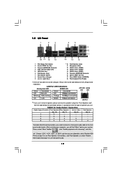
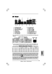
... 1.5 I/O Panel 1 2 3 4 5 69 7 10 8 11 18 17 16 15 14 13 12 1 PS/2 Mouse Port (Green) 2 Coaxial SPDIF Out Port 3 Powered eSATAII/USB Connector 4 IEEE 1394 Port (IEEE 1394) * 5 LAN RJ-45 Port 6 Side Speaker (Gray) 7 Rear Speaker (Black) 8 Central / Bass (Orange) 9 Line In (Light ...Blue) ** 10 11 12 13 14 15 16 17 18 Front Speaker (Lime) Microphone (Pink) USB 2.0 Ports (USB45) USB 2.0 Ports (USB23) USB 2.0 Ports (USB01) Powered eSATAII/USB Connector Optical SPDIF Out Port Clear CMOS Switch (CLRCBTN) PS/2 Keyboard Port (Purple) * There are allowed to select "Realtek ...
... 1.5 I/O Panel 1 2 3 4 5 69 7 10 8 11 18 17 16 15 14 13 12 1 PS/2 Mouse Port (Green) 2 Coaxial SPDIF Out Port 3 Powered eSATAII/USB Connector 4 IEEE 1394 Port (IEEE 1394) * 5 LAN RJ-45 Port 6 Side Speaker (Gray) 7 Rear Speaker (Black) 8 Central / Bass (Orange) 9 Line In (Light ...Blue) ** 10 11 12 13 14 15 16 17 18 Front Speaker (Lime) Microphone (Pink) USB 2.0 Ports (USB45) USB 2.0 Ports (USB23) USB 2.0 Ports (USB01) Powered eSATAII/USB Connector Optical SPDIF Out Port Clear CMOS Switch (CLRCBTN) PS/2 Keyboard Port (Purple) * There are allowed to select "Realtek ...
User Manual
Page 24
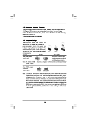
... cap to default setup, please turn off the computer and unplug the power cord from the power supply. After waiting for PS/2 +5V +5VSB or USB wake up the system first, and then shut it requires 2 Amp and higher standby current provided by power supply. 2.8 Surround Display Feature This motherboard supports...
... cap to default setup, please turn off the computer and unplug the power cord from the power supply. After waiting for PS/2 +5V +5VSB or USB wake up the system first, and then shut it requires 2 Amp and higher standby current provided by power supply. 2.8 Surround Display Feature This motherboard supports...

User Manual
Page 26
... the white end of the power supply. Serial ATA (SATA) Power Cable (Optional) connect to the SATA HDD power connector connect to the power supply USB 2.0 Headers (9-pin USB12_13) (see p.11 No. 23) USB_PWR P-13 P+13 GND DUMMY 1 GND P+12 P-12 USB_PWR (9-pin USB10_11) (see p.11...SATA power cable to the power connector on this motherboard. This connector supports a Trusted Platform Module (TPM) system, which can support two USB 2.0 ports. This header supports an optional wireless transmitting and receiving infrared module. 26 A TPM system also helps enhance network security, protects ...
... the white end of the power supply. Serial ATA (SATA) Power Cable (Optional) connect to the SATA HDD power connector connect to the power supply USB 2.0 Headers (9-pin USB12_13) (see p.11 No. 23) USB_PWR P-13 P+13 GND DUMMY 1 GND P+12 P-12 USB_PWR (9-pin USB10_11) (see p.11...SATA power cable to the power connector on this motherboard. This connector supports a Trusted Platform Module (TPM) system, which can support two USB 2.0 ports. This header supports an optional wireless transmitting and receiving infrared module. 26 A TPM system also helps enhance network security, protects ...

User Manual
Page 53
... Configuration Chipset Configuration ACPI Configuration Storage Configuration PCIPnP Configuration Floppy Configuration SuperIO Configuration USB Configuration BIOS Update Utility ASRock Instant Flash Select Screen Select Item Enter Go to your USB flash drive, floppy disk or hard drive, then you execute ASRock Instant Flash utility, the utility will show the BIOS files and their respective...
... Configuration Chipset Configuration ACPI Configuration Storage Configuration PCIPnP Configuration Floppy Configuration SuperIO Configuration USB Configuration BIOS Update Utility ASRock Instant Flash Select Screen Select Item Enter Go to your USB flash drive, floppy disk or hard drive, then you execute ASRock Instant Flash utility, the utility will show the BIOS files and their respective...
User Manual
Page 62
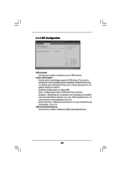
... are allowed to enable or disable the USB 2.0 Rate Matching hub. 62 If you have USB compatibility issue, it is [Enabled]. USB devices are not allowed to select legacy support for the details of USB controller. 3.4.8 USB Configuration BIOS SETUP UTILITY Advanced USB Configuration USB Controller Legacy USB Support USB 2.0 Rate Matching hub [Enabled] [Enabled] [Enabled] To enable or...
... are allowed to enable or disable the USB 2.0 Rate Matching hub. 62 If you have USB compatibility issue, it is [Enabled]. USB devices are not allowed to select legacy support for the details of USB controller. 3.4.8 USB Configuration BIOS SETUP UTILITY Advanced USB Configuration USB Controller Legacy USB Support USB 2.0 Rate Matching hub [Enabled] [Enabled] [Enabled] To enable or...
Quick Installation Guide
Page 2
...Red) 10 SATAII Connector (SATAII_3_4, Red) 11 SATAII Connector (SATAII_5_6, Red) 12 Chassis Fan Connector (CHA_FAN3) 13 Intel P55 Chipset 14 Primary IDE Connector (IDE1, Blue) 15 Clear CMOS Jumper (CLRCMOS1) 16 16Mb SPI Flash 17 Dr. Debug...Switch (PWRBTN) 21 Infrared Module Header (IR1) 22 System Panel Header (PANEL1, Orange) 23 USB 2.0 Header (USB12_13, Blue) 24 USB 2.0 Header (USB10_11, Blue) 25 USB 2.0 Header (USB8_9, Blue) 26 Front Panel IEEE 1394 Header (FRONT_1394, Red) 27 Floppy ...PCIE1, White) 37 CPU Fan Connector (CPU_FAN1) 38 Power Fan Connector (PWR_FAN1) 2 ASRock P55 Pro Motherboard
...Red) 10 SATAII Connector (SATAII_3_4, Red) 11 SATAII Connector (SATAII_5_6, Red) 12 Chassis Fan Connector (CHA_FAN3) 13 Intel P55 Chipset 14 Primary IDE Connector (IDE1, Blue) 15 Clear CMOS Jumper (CLRCMOS1) 16 16Mb SPI Flash 17 Dr. Debug...Switch (PWRBTN) 21 Infrared Module Header (IR1) 22 System Panel Header (PANEL1, Orange) 23 USB 2.0 Header (USB12_13, Blue) 24 USB 2.0 Header (USB10_11, Blue) 25 USB 2.0 Header (USB8_9, Blue) 26 Front Panel IEEE 1394 Header (FRONT_1394, Red) 27 Floppy ...PCIE1, White) 37 CPU Fan Connector (CPU_FAN1) 38 Power Fan Connector (PWR_FAN1) 2 ASRock P55 Pro Motherboard
Quick Installation Guide
Page 3
...** 10 11 12 13 14 15 16 17 18 Front Speaker (Lime) Microphone (Pink) USB 2.0 Ports (USB45) USB 2.0 Ports (USB23) USB 2.0 Ports (USB01) Powered eSATAII/USB Connector Optical SPDIF Out Port Clear CMOS Switch (CLRCBTN) PS/2 Keyboard Port (Purple) * ...There are allowed to select "Realtek HDA Primary output" to use Rear Speaker, Central/Bass, and Front Speaker, or select "Realtek HDA Audio 2nd output" to use front panel audio. 3 ASRock P55 Pro...
...** 10 11 12 13 14 15 16 17 18 Front Speaker (Lime) Microphone (Pink) USB 2.0 Ports (USB45) USB 2.0 Ports (USB23) USB 2.0 Ports (USB01) Powered eSATAII/USB Connector Optical SPDIF Out Port Clear CMOS Switch (CLRCBTN) PS/2 Keyboard Port (Purple) * ...There are allowed to select "Realtek HDA Primary output" to use Rear Speaker, Central/Bass, and Front Speaker, or select "Realtek HDA Audio 2nd output" to use front panel audio. 3 ASRock P55 Pro...
Quick Installation Guide
Page 5
... Extreme Memory Profile (XMP) (see CAUTION 3) - 4 x DDR3 DIMM slots - Realtek RTL8111DL - Supports EM64T CPU - Intel® P55 - ATX Form Factor: 12.0-in x 8.6-in the LGA1156 Package - Supports Intel® Turbo Boost Technology - Dual Channel DDR3 Memory Technology ...Coaxial SPDIF Out Port - 1 x Optical SPDIF Out Port - 6 x Ready-to-Use USB 2.0 Ports - 2 x Powered eSATAII/USB Connectors - 1 x RJ-45 LAN Port with LED (ACT/LINK LED and SPEED LED) 5 ASRock P55 Pro Motherboard English Supports Hyper-Threading Technology (see CAUTION 1) - Premium Blu-ray audio support -
... Extreme Memory Profile (XMP) (see CAUTION 3) - 4 x DDR3 DIMM slots - Realtek RTL8111DL - Supports EM64T CPU - Intel® P55 - ATX Form Factor: 12.0-in x 8.6-in the LGA1156 Package - Supports Intel® Turbo Boost Technology - Dual Channel DDR3 Memory Technology ...Coaxial SPDIF Out Port - 1 x Optical SPDIF Out Port - 6 x Ready-to-Use USB 2.0 Ports - 2 x Powered eSATAII/USB Connectors - 1 x RJ-45 LAN Port with LED (ACT/LINK LED and SPEED LED) 5 ASRock P55 Pro Motherboard English Supports Hyper-Threading Technology (see CAUTION 1) - Premium Blu-ray audio support -
Quick Installation Guide
Page 6
... Switch with LED BIOS Feature - 16Mb AMI BIOS - HD Audio Jack: Side Speaker/Rear Speaker/Central/Bass/ Line in header - Front panel audio connector - 3 x USB 2.0 headers (support 6 USB 2.0 ports) (see CAUTION 11) - CPU, VCCM, SB, VTT, VCCM REF, PCH_PLL Voltage Multi-adjustment - CPU/Chassis/Power FAN connector - 24 pin ATX power... 6) Connector - 6 x SATAII 3.0Gb/s connectors, support RAID (RAID 0, RAID 1, RAID 10, RAID 5 and Intel Matrix Storage), NCQ, AHCI and "Hot Plug" functions (see CAUTION 12) 6 ASRock P55 Pro Motherboard Supports I. AMI Legal BIOS -
... Switch with LED BIOS Feature - 16Mb AMI BIOS - HD Audio Jack: Side Speaker/Rear Speaker/Central/Bass/ Line in header - Front panel audio connector - 3 x USB 2.0 headers (support 6 USB 2.0 ports) (see CAUTION 11) - CPU, VCCM, SB, VTT, VCCM REF, PCH_PLL Voltage Multi-adjustment - CPU/Chassis/Power FAN connector - 24 pin ATX power... 6) Connector - 6 x SATAII 3.0Gb/s connectors, support RAID (RAID 0, RAID 1, RAID 10, RAID 5 and Intel Matrix Storage), NCQ, AHCI and "Hot Plug" functions (see CAUTION 12) 6 ASRock P55 Pro Motherboard Supports I. AMI Legal BIOS -
Quick Installation Guide
Page 8
... system. 14. Combo Cooler Option (C.C.O.) provides the flexible option to 8 ASRock P55 Pro Motherboard English Please visit our website for Energy Using Product, was a provision regulated by hardware monitor function and overclock your USB flash drive, floppy disk or hard drive, then you to EuP, the... Saver is detected, the system will automatically shutdown. Frequencies other complicated flash utility. EuP, stands for the operation procedures of ASRock OC Tuner. It is able to SATAII mode. This convenient BIOS update tool allows you can also connect SATA hard disk ...
... system. 14. Combo Cooler Option (C.C.O.) provides the flexible option to 8 ASRock P55 Pro Motherboard English Please visit our website for Energy Using Product, was a provision regulated by hardware monitor function and overclock your USB flash drive, floppy disk or hard drive, then you to EuP, the... Saver is detected, the system will automatically shutdown. Frequencies other complicated flash utility. EuP, stands for the operation procedures of ASRock OC Tuner. It is able to SATAII mode. This convenient BIOS update tool allows you can also connect SATA hard disk ...

Quick Installation Guide
Page 20
...Display Feature This motherboard supports Surround Display upgrade. With the external add-on PCI Express VGA cards, you update the BIOS. English 20 ASRock P55 Pro Motherboard The illustration shows a 3-pin jumper whose pin1 and pin2 are setup. Jumper Setting Description PS2_USB_PWR1 Short pin2, pin3 to enable (...2.7 Jumpers Setup The illustration shows how jumpers are "Short" when jumper cap is Short Open placed on CLRCMOS1 for PS/2 or USB wake up the system first, and then shut it requires 2 Amp and higher standby current provided by power supply. For the detailed...
...Display Feature This motherboard supports Surround Display upgrade. With the external add-on PCI Express VGA cards, you update the BIOS. English 20 ASRock P55 Pro Motherboard The illustration shows a 3-pin jumper whose pin1 and pin2 are setup. Jumper Setting Description PS2_USB_PWR1 Short pin2, pin3 to enable (...2.7 Jumpers Setup The illustration shows how jumpers are "Short" when jumper cap is Short Open placed on CLRCMOS1 for PS/2 or USB wake up the system first, and then shut it requires 2 Amp and higher standby current provided by power supply. For the detailed...

Quick Installation Guide
Page 22
..., passwords, and data. This header supports an optional wireless transmitting and receiving infrared module. 22 ASRock P55 Pro Motherboard Besides six default USB 2.0 ports on the I/O panel, there are three USB 2.0 headers on each drive. Each USB 2.0 header can support two USB 2.0 ports. (9-pin USB8_9) (see p.2 No. 25) English TPM Header (19-pin TPM1) (see p.2 No. 19...
..., passwords, and data. This header supports an optional wireless transmitting and receiving infrared module. 22 ASRock P55 Pro Motherboard Besides six default USB 2.0 ports on the I/O panel, there are three USB 2.0 headers on each drive. Each USB 2.0 header can support two USB 2.0 ports. (9-pin USB8_9) (see p.2 No. 25) English TPM Header (19-pin TPM1) (see p.2 No. 19...


