User Manual
Page 3
... (DIMM 12 2.4 Expansion Slots (PCI, AMR, and AGP Slots 13 2.5 Jumpers Setup 14 2.6 Onboard Headers and Connectors 15 2.7 Serial ATA (SATA) Hard Disks Installation 18 2.8 Hot Plug and Hot Swap Functions for SATA HDDs ....... 18 2.9 Installing Windows 2000 / Windows XP With RAID Functions 19 2.10 Installing Windows 98 / ME / 2000 / XP Without...
... (DIMM 12 2.4 Expansion Slots (PCI, AMR, and AGP Slots 13 2.5 Jumpers Setup 14 2.6 Onboard Headers and Connectors 15 2.7 Serial ATA (SATA) Hard Disks Installation 18 2.8 Hot Plug and Hot Swap Functions for SATA HDDs ....... 18 2.9 Installing Windows 2000 / Windows XP With RAID Functions 19 2.10 Installing Windows 98 / ME / 2000 / XP Without...
User Manual
Page 5
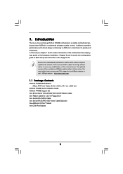
You may find the latest memory and CPU support lists on ASRock website without notice. ASRock website http://www.asrock.com 1.1 Package Contents ASRock P4VM8 Motherboard (Micro ATX Form Factor: 9.6-in x 8.0-in Floppy Drive One Serial ATA (SATA) Cable One Serial ATA (SATA) HDD Power Cable(Optional) One ASRock I/O PlusTM Shield One COM Port Bracket 5 It delivers excellent performance...
You may find the latest memory and CPU support lists on ASRock website without notice. ASRock website http://www.asrock.com 1.1 Package Contents ASRock P4VM8 Motherboard (Micro ATX Form Factor: 9.6-in x 8.0-in Floppy Drive One Serial ATA (SATA) Cable One Serial ATA (SATA) HDD Power Cable(Optional) One ASRock I/O PlusTM Shield One COM Port Bracket 5 It delivers excellent performance...

User Manual
Page 6
..., FSB @ 800/533/400 MHz, with Intel® Hyper-Threading Technology ready (see CAUTION 1) South Bridge: VIA VT8237R, supports USB 2.0, ATA 133, SATA 1.5Gb/s Memory: 2 DDR DIMM Slots: DDR1 and DDR2 1 DDR DIMM Slot Supports PC3200 (DDR400), Max. 1GB, 2 DDR DIMM Slots Supports PC2700 (...802.3u (10/100 Ethernet), supports Wake-On-LAN Hardware Monitor: CPU temperature sensing Chassis temperature sensing CPU overheat shutdown to protect CPU life (ASRock U-COP)(see CAUTION 2) CPU fan tachometer Chassis fan tachometer Voltage monitoring: +12V, +5V, +3.3V, Vcore PCI slots: 3 slots with ...
..., FSB @ 800/533/400 MHz, with Intel® Hyper-Threading Technology ready (see CAUTION 1) South Bridge: VIA VT8237R, supports USB 2.0, ATA 133, SATA 1.5Gb/s Memory: 2 DDR DIMM Slots: DDR1 and DDR2 1 DDR DIMM Slot Supports PC3200 (DDR400), Max. 1GB, 2 DDR DIMM Slots Supports PC2700 (...802.3u (10/100 Ethernet), supports Wake-On-LAN Hardware Monitor: CPU temperature sensing Chassis temperature sensing CPU overheat shutdown to protect CPU life (ASRock U-COP)(see CAUTION 2) CPU fan tachometer Chassis fan tachometer Voltage monitoring: +12V, +5V, +3.3V, Vcore PCI slots: 3 slots with ...
User Manual
Page 8
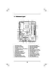
... LAN PHY 1 AUDIO1 CMOS Battery JR1 JL1 CLRCMOS1 5.1CH CD1 AUX1 Audio CODEC AMR1 VPIMACh80ip0set AGP 8X ATA133 1.5V_AGP1 IDE1 IDE2 PCI 1 ` P4VM8 PCI 2 USB2.0 PCI 3 1 COM1 VIA VT8237R SATA 1 USB67 PANEL 1 PLED PWRBTN 1 1 SPEAKER1 HDLED RESET SATA2 SATA1 DDR400 Prescott 800 DDR1 (64/72 bit, 184-pin module) DDR2 (64/72...
... LAN PHY 1 AUDIO1 CMOS Battery JR1 JL1 CLRCMOS1 5.1CH CD1 AUX1 Audio CODEC AMR1 VPIMACh80ip0set AGP 8X ATA133 1.5V_AGP1 IDE1 IDE2 PCI 1 ` P4VM8 PCI 2 USB2.0 PCI 3 1 COM1 VIA VT8237R SATA 1 USB67 PANEL 1 PLED PWRBTN 1 1 SPEAKER1 HDLED RESET SATA2 SATA1 DDR400 Prescott 800 DDR1 (64/72 bit, 184-pin module) DDR2 (64/72...
User Manual
Page 15
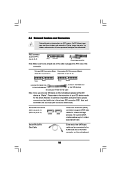
...9) Pin1 FLOPPY1 the red-striped side to Pin1 Note: Make sure the red-striped side of the cable is plugged into Pin1 side of the SATA data cable can be connected to the secondary IDE connector (IDE2, black). Do NOT place jumper caps over the headers and connectors will cause permanent... (Blue) Secondary IDE Connector (Black) (39-pin IDE1, see p.8, No. 11) (39-pin IDE2, see p.8, No. 15) SATA2 SATA1 These two Serial ATA (SATA) connectors support SATA data cables for the details. Besides, to the IDE devices 80-conductor ATA 66/100/133 cable Note: If you use only one IDE...
...9) Pin1 FLOPPY1 the red-striped side to Pin1 Note: Make sure the red-striped side of the cable is plugged into Pin1 side of the SATA data cable can be connected to the secondary IDE connector (IDE2, black). Do NOT place jumper caps over the headers and connectors will cause permanent... (Blue) Secondary IDE Connector (Black) (39-pin IDE1, see p.8, No. 11) (39-pin IDE2, see p.8, No. 15) SATA2 SATA1 These two Serial ATA (SATA) connectors support SATA data cables for the details. Besides, to the IDE devices 80-conductor ATA 66/100/133 cable Note: If you use only one IDE...
User Manual
Page 16
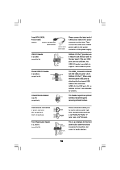
R MIC-POWER MIC This is an interface for the front panel audio cable that allows convenient connection and control of SATA power cable to the power connector on ASRock I /O PlusTM. USB 2.0 Header (9-pin USB67) (see p.8, No. 6) IRTX +5V DUMMY 1 GND IRRX... 28) P-5 P+5 GND USB_PWR P-4 P+4 GND DUMMY Infrared Module Header (5-pin IR1) (see p.8, No. 18) USB_PWR P-7 P+7 GND DUMMY 1 GND P+6 P-6 USB_PWR ASRock I/O PlusTM provides you to support 2 extra USB 2.0 ports. This header supports an optional wireless transmitting and receiving infrared module. L GND A U D - Serial ATA...
R MIC-POWER MIC This is an interface for the front panel audio cable that allows convenient connection and control of SATA power cable to the power connector on ASRock I /O PlusTM. USB 2.0 Header (9-pin USB67) (see p.8, No. 6) IRTX +5V DUMMY 1 GND IRRX... 28) P-5 P+5 GND USB_PWR P-4 P+4 GND DUMMY Infrared Module Header (5-pin IR1) (see p.8, No. 18) USB_PWR P-7 P+7 GND DUMMY 1 GND P+6 P-6 USB_PWR ASRock I/O PlusTM provides you to support 2 extra USB 2.0 ports. This header supports an optional wireless transmitting and receiving infrared module. L GND A U D - Serial ATA...
User Manual
Page 18
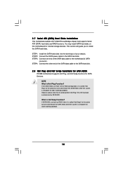
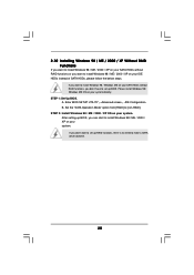
STEP 4: Connect the other end of the SATA data cable to the SATA hard disk. 2.8 Hot Plug and Hot Swap Functions for SATA HDDs P4VM8 motherboard supports Hot Plug and Hot Swap functions for the action to insert and remove the SATA HDDs while the system is called "Hot Plug" for internal storage... devices. What is Hot Plug Function? If SATA HDDs are NOT set for RAID ...
STEP 4: Connect the other end of the SATA data cable to the SATA hard disk. 2.8 Hot Plug and Hot Swap Functions for SATA HDDs P4VM8 motherboard supports Hot Plug and Hot Swap functions for the action to insert and remove the SATA HDDs while the system is called "Hot Plug" for internal storage... devices. What is Hot Plug Function? If SATA HDDs are NOT set for RAID ...
User Manual
Page 19
...the support CD, "Guide to VIA RAID Tool", which is located in the Support CD for boot devices selection appears. A. Start to use both "SATA RAID BIOS" and "VIA RAID Tool" for RAID configuration. After the installation of system boot-up, press key,and then a window for proper configuration... to manage RAID functions, you need to check the installation guide in the folder at the following path: .. \ VIA RAID Tool 1. Insert the ASRock Support CD into the floppy diskette. C. The system will see the message on the screen, "Do you want to install Windows 2000 / Windows XP...
...the support CD, "Guide to VIA RAID Tool", which is located in the Support CD for boot devices selection appears. A. Start to use both "SATA RAID BIOS" and "VIA RAID Tool" for RAID configuration. After the installation of system boot-up, press key,and then a window for proper configuration... to manage RAID functions, you need to check the installation guide in the folder at the following path: .. \ VIA RAID Tool 1. Insert the ASRock Support CD into the floppy diskette. C. The system will see the message on the screen, "Do you want to install Windows 2000 / Windows XP...
User Manual
Page 20
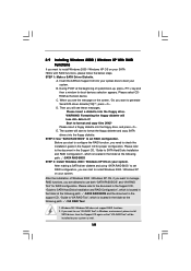
... on your system. B. STEP 2: Install Windows 98 / ME / 2000 / XP OS on your system. If you want to install Windows 98 / Windows ME on your SATA HDDs without RAID functions or you want to [non-RAID]. Enter BIOS SETUP UTILITY ¡÷Advanced screen ¡÷IDE Configuration. Set the... Windows 98 / ME / 2000 / XP Without RAID Functions If you want to install Windows 98 / ME / 2000 / XP on your SATA HDDs without RAID functions, you don't have to make a SATA driver diskette. 20 After setting up BIOS. Please install Windows 98 / Windows ME OS on your system directly. STEP 1: Set Up...
... on your system. B. STEP 2: Install Windows 98 / ME / 2000 / XP OS on your system. If you want to install Windows 98 / Windows ME on your SATA HDDs without RAID functions or you want to [non-RAID]. Enter BIOS SETUP UTILITY ¡÷Advanced screen ¡÷IDE Configuration. Set the... Windows 98 / ME / 2000 / XP Without RAID Functions If you want to install Windows 98 / ME / 2000 / XP on your SATA HDDs without RAID functions, you don't have to make a SATA driver diskette. 20 After setting up BIOS. Please install Windows 98 / Windows ME OS on your system directly. STEP 1: Set Up...
User Manual
Page 27
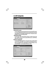
... Vendor Size LBA Mode Block Mode PIO Mode Async DMA Ultra DMA S.M.A.R.T. 3.3.4 IDE Configuration BIOS SETUP UTILITY Advanced IDE Configuration OnBoard IDE Controller SATA Operation Mode Primary IDE Master Primary IDE Slave Secondary IDE Master Secondary IDE Slave [Both] [RAID] [Hard Disk] [Not Detected] [Not... IDE Device Configuration You may set the IDE configuration for the device that you don't want to adjust SATA Operation Mode. If you specify. We will disable the both. SATA Operation Mode Use this option is [RAID]. The default value of "Primary IDE Slave", "Secondary IDE ...
... Vendor Size LBA Mode Block Mode PIO Mode Async DMA Ultra DMA S.M.A.R.T. 3.3.4 IDE Configuration BIOS SETUP UTILITY Advanced IDE Configuration OnBoard IDE Controller SATA Operation Mode Primary IDE Master Primary IDE Slave Secondary IDE Master Secondary IDE Slave [Both] [RAID] [Hard Disk] [Not Detected] [Not... IDE Device Configuration You may set the IDE configuration for the device that you don't want to adjust SATA Operation Mode. If you specify. We will disable the both. SATA Operation Mode Use this option is [RAID]. The default value of "Primary IDE Slave", "Secondary IDE ...
User Manual
Page 33
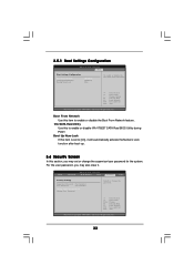
3.5.1 Boot Settings Configuration BIOS SETUP UTILITY Boot Boot Settings Configuration Boot From Network VIA SATA Raid Utility Bootup Num-Lock [Disabled] [Enabled] [On] To enable or disable the boot from network feature. +F1 F9 F10 ESC Select Screen Select Item ... it will automatically activate the Numeric Lock function after boot-up. 3.6 Security Screen In this item to enable or disable VIA VT8237 SATA Raid BIOS Utility during POST. VIA SATA Raid Utility Use this item is set to [On], it . Select Screen Select Item Enter Change F1 General Help F9 Load Defaults...
3.5.1 Boot Settings Configuration BIOS SETUP UTILITY Boot Boot Settings Configuration Boot From Network VIA SATA Raid Utility Bootup Num-Lock [Disabled] [Enabled] [On] To enable or disable the boot from network feature. +F1 F9 F10 ESC Select Screen Select Item ... it will automatically activate the Numeric Lock function after boot-up. 3.6 Security Screen In this item to enable or disable VIA VT8237 SATA Raid BIOS Utility during POST. VIA SATA Raid Utility Use this item is set to [On], it . Select Screen Select Item Enter Change F1 General Help F9 Load Defaults...
