
User Manual
Page 5
... content of this motherboard, please visit our website for purchasing ASRock P45DE motherboard, a reliable motherboard produced under ASRock's consistently stringent quality control. www.asrock.com/support/index.asp 1.1 Package Contents ASRock P45DE Motherboard (ATX Form Factor: 12.0-in x 8.5-in, 30.5 cm x 21.6 cm) ASRock P45DE Quick Installation Guide ASRock P45DE Support CD One 80-conductor Ultra ATA 66/100/133...
... content of this motherboard, please visit our website for purchasing ASRock P45DE motherboard, a reliable motherboard produced under ASRock's consistently stringent quality control. www.asrock.com/support/index.asp 1.1 Package Contents ASRock P45DE Motherboard (ATX Form Factor: 12.0-in x 8.5-in, 30.5 cm x 21.6 cm) ASRock P45DE Quick Installation Guide ASRock P45DE Support CD One 80-conductor Ultra ATA 66/100/133...

Quick Installation Guide
Page 1
.... CALIFORNIA, USA ONLY The Lithium battery adopted on this guide may or may cause undesired operation. All rights reserved. 1 ASRock P45DE Motherboard English Copyright Notice: No part of this installation guide may be liable for any indirect, special, incidental, or consequential damages... in Perchlorate Best Management Practices (BMP) regulations passed by the purchaser for backup purpose, without intent to infringe. ASRock assumes no event shall ASRock, its directors, officers, employees, or agents be reproduced, transcribed, transmitted, or translated in any language, in any...
.... CALIFORNIA, USA ONLY The Lithium battery adopted on this guide may or may cause undesired operation. All rights reserved. 1 ASRock P45DE Motherboard English Copyright Notice: No part of this installation guide may be liable for any indirect, special, incidental, or consequential damages... in Perchlorate Best Management Practices (BMP) regulations passed by the purchaser for backup purpose, without intent to infringe. ASRock assumes no event shall ASRock, its directors, officers, employees, or agents be reproduced, transcribed, transmitted, or translated in any language, in any...

Quick Installation Guide
Page 2
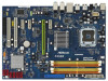
... Front Panel Audio Header (HD_AUDIO1, Lime) 33 PCI Express 2.0 x16 Slot (PCIE2, Green) 34 Internal Audio Connector: CD1 (Black) 35 PCI Express x1 Slot (PCIE1) 2 ASRock P45DE Motherboard Motherboard Layout English 1 ATX 12V Connector (ATX12V1) 2 775-Pin CPU Socket 3 North Bridge Controller 4 CPU Fan Connector (CPU_FAN1) 5 PS2_USB_PWR1 Jumper 6 2 x 240-pin DDR2 DIMM...
... Front Panel Audio Header (HD_AUDIO1, Lime) 33 PCI Express 2.0 x16 Slot (PCIE2, Green) 34 Internal Audio Connector: CD1 (Black) 35 PCI Express x1 Slot (PCIE1) 2 ASRock P45DE Motherboard Motherboard Layout English 1 ATX 12V Connector (ATX12V1) 2 775-Pin CPU Socket 3 North Bridge Controller 4 CPU Fan Connector (CPU_FAN1) 5 PS2_USB_PWR1 Jumper 6 2 x 240-pin DDR2 DIMM...

Quick Installation Guide
Page 3
... LED next to the table below for Audio Output Connection Audio Output Channels Front Speaker Rear Speaker Central / Bass Side Speaker (No. 7) (No. 4) (No. 5) (No. 3) 2 V -- -- -- 4 V V -- -- 6 V V V -- 8 V V V V 3 ASRock P45DE Motherboard English
... LED next to the table below for Audio Output Connection Audio Output Channels Front Speaker Rear Speaker Central / Bass Side Speaker (No. 7) (No. 4) (No. 5) (No. 3) 2 V -- -- -- 4 V V -- -- 6 V V V -- 8 V V V V 3 ASRock P45DE Motherboard English

Quick Installation Guide
Page 4
...® VistaTM / VistaTM 64-bit OS: Please click "VIA HD Audio Deck" icon , and click "Advanced Options" on the left side on your system. English 4 ASRock P45DE Motherboard If you are allowed to save your change . To enable Multi-Streaming function, you install. After restarting your computer, you will be disabled. Please...
...® VistaTM / VistaTM 64-bit OS: Please click "VIA HD Audio Deck" icon , and click "Advanced Options" on the left side on your system. English 4 ASRock P45DE Motherboard If you are allowed to save your change . To enable Multi-Streaming function, you install. After restarting your computer, you will be disabled. Please...

Quick Installation Guide
Page 5
... guide. 1. This Quick Installation Guide contains introduction of this motherboard, please visit our website for purchasing ASRock P45DE motherboard, a reliable motherboard produced under ASRock's consistently stringent quality control. Introduction Thank you for specific information about the model you require technical support ...related to this manual will be found in the user manual presented in , 30.5 cm x 21.6 cm) ASRock P45DE Quick Installation Guide ASRock P45DE Support CD One 80-conductor Ultra ATA 66/100/133 IDE Ribbon Cable Two Serial ATA (SATA) Data Cables (...
... guide. 1. This Quick Installation Guide contains introduction of this motherboard, please visit our website for purchasing ASRock P45DE motherboard, a reliable motherboard produced under ASRock's consistently stringent quality control. Introduction Thank you for specific information about the model you require technical support ...related to this manual will be found in the user manual presented in , 30.5 cm x 21.6 cm) ASRock P45DE Quick Installation Guide ASRock P45DE Support CD One 80-conductor Ultra ATA 66/100/133 IDE Ribbon Cable Two Serial ATA (SATA) Data Cables (...

Quick Installation Guide
Page 6
... processors - Max. capacity of system memory: 16GB (see CAUTION 5) - Supports Hyper-Threading Technology (see CAUTION 8) - 1 x ATA133 IDE connector (supports 2 x IDE devices) - 1 x Floppy connector - 1 x IR header ASRock P45DE Motherboard English Northbridge: Intel® P45 - Compatible with LED (ACT/LINK LED and SPEED LED) - Supports EM64T CPU - HD Audio Jack: Side Speaker/Rear Speaker...
... processors - Max. capacity of system memory: 16GB (see CAUTION 5) - Supports Hyper-Threading Technology (see CAUTION 8) - 1 x ATA133 IDE connector (supports 2 x IDE devices) - 1 x Floppy connector - 1 x IR header ASRock P45DE Motherboard English Northbridge: Intel® P45 - Compatible with LED (ACT/LINK LED and SPEED LED) - Supports EM64T CPU - HD Audio Jack: Side Speaker/Rear Speaker...

Quick Installation Guide
Page 7
... - CPU, DRAM, NB, SB, VTT Voltage Multi-adjustment - O. Drivers, Utilities, AntiVirus Software (Trial Version) Unique Feature - ASRock OC Tuner (see CAUTION 9) BIOS Feature - 8Mb AMI BIOS - Intelligent Energy Saver (see CAUTION 13) - Chassis Fan Tachometer - ACPI 1.1 Compliance ... +12V, +5V, +3.3V, CPU Vcore OS - FCC, CE, WHQL * For detailed product information, please visit our website: http://www.asrock.com English 7 ASRock P45DE Motherboard - 1 x COM port header - 1 x HDMI_SPDIF header - CPU/Chassis FAN connector - 24 pin ATX power connector - 8 pin 12V...
... - CPU, DRAM, NB, SB, VTT Voltage Multi-adjustment - O. Drivers, Utilities, AntiVirus Software (Trial Version) Unique Feature - ASRock OC Tuner (see CAUTION 9) BIOS Feature - 8Mb AMI BIOS - Intelligent Energy Saver (see CAUTION 13) - Chassis Fan Tachometer - ACPI 1.1 Compliance ... +12V, +5V, +3.3V, CPU Vcore OS - FCC, CE, WHQL * For detailed product information, please visit our website: http://www.asrock.com English 7 ASRock P45DE Motherboard - 1 x COM port header - 1 x HDMI_SPDIF header - CPU/Chassis FAN connector - 24 pin ATX power connector - 8 pin 12V...

Quick Installation Guide
Page 8
... Due to read the "SATAII Hard Disk Setup Guide" on page 3 for system usage under Windows® environment. ASRock website: http://www.asrock.com English 8 ASRock P45DE Motherboard We are not responsible for the CPU FSB frequency and its corresponding memory support frequency. Please read "Untied Overclocking... the components and devices of your system stability, or even cause damage to SATAII connector, please read the installation guide of ASRock OC Tuner. Please check the table on page 27 of "User Manual" in the BIOS, applying Untied Overclocking Technology, or...
... Due to read the "SATAII Hard Disk Setup Guide" on page 3 for system usage under Windows® environment. ASRock website: http://www.asrock.com English 8 ASRock P45DE Motherboard We are not responsible for the CPU FSB frequency and its corresponding memory support frequency. Please read "Untied Overclocking... the components and devices of your system stability, or even cause damage to SATAII connector, please read the installation guide of ASRock OC Tuner. Please check the table on page 27 of "User Manual" in the BIOS, applying Untied Overclocking Technology, or...

Quick Installation Guide
Page 9
...remember to perform over-clocking. Please refer to provide exceptional power saving and improve power efficiency without sacrificing computing performance. ASRock website: http://www.asrock.com 12. In other than the recommended CPU bus frequencies may cause the instability of Intelligent Energy Saver. Frequencies ... the CPU. 13. Before you install the PC system. 14. Please visit our website for detailed setup. 9 ASRock P45DE Motherboard English While CPU overheat is not supported under Windows® 2000. AHCI function is detected, the system will automatically shutdown. 11...
...remember to perform over-clocking. Please refer to provide exceptional power saving and improve power efficiency without sacrificing computing performance. ASRock website: http://www.asrock.com 12. In other than the recommended CPU bus frequencies may cause the instability of Intelligent Energy Saver. Frequencies ... the CPU. 13. Before you install the PC system. 14. Please visit our website for detailed setup. 9 ASRock P45DE Motherboard English While CPU overheat is not supported under Windows® 2000. AHCI function is detected, the system will automatically shutdown. 11...

Quick Installation Guide
Page 10
... or touch a safety grounded object before touching any component, place it on the carpet or the like. Otherwise, the CPU will be seriously damaged. 10 ASRock P45DE Motherboard English To avoid damaging the motherboard components due to do so may damage the motherboard. 2.1 CPU Installation For the installation of the following precautions...
... or touch a safety grounded object before touching any component, place it on the carpet or the like. Otherwise, the CPU will be seriously damaged. 10 ASRock P45DE Motherboard English To avoid damaging the motherboard components due to do so may damage the motherboard. 2.1 CPU Installation For the installation of the following precautions...

Quick Installation Guide
Page 11
... and properly mated to match the two orientation key notches of the CPU with black lines. Rotate the load plate to assist in removal. 11 ASRock P45DE Motherboard English black line black line Step 2-2. Insert the 775-LAND CPU: Step 2-1. Pin1 orientation key notch orientation key notch Pin1 alignment key alignment key...
... and properly mated to match the two orientation key notches of the CPU with black lines. Rotate the load plate to assist in removal. 11 ASRock P45DE Motherboard English black line black line Step 2-2. Insert the 775-LAND CPU: Step 2-1. Pin1 orientation key notch orientation key notch Pin1 alignment key alignment key...

Quick Installation Guide
Page 12
... material onto center of the heatsink for after service. Step 3. Close the socket: Step 4-1. 1. Step 4-3. Align fasteners with fan operation or contact other components. 12 ASRock P45DE Motherboard English
... material onto center of the heatsink for after service. Step 3. Close the socket: Step 4-1. 1. Step 4-3. Align fasteners with fan operation or contact other components. 12 ASRock P45DE Motherboard English

Quick Installation Guide
Page 13
... in Dual Channel B (DDRII_A2 and DDRII_B2; Dual Channel Memory Configurations DDRII_A1 DDRII_A2 DDRII_B1 DDRII_B2 (Yellow Slot) (Orange Slot) (Yellow Slot) (Orange Slot) (1) Populated - English 13 ASRock P45DE Motherboard Yellow slots; see p.2 No.7), so that Dual Channel Memory Technology can be damaged. Populated - Orange slots; For dual channel configuration, you want to install...
... in Dual Channel B (DDRII_A2 and DDRII_B2; Dual Channel Memory Configurations DDRII_A1 DDRII_A2 DDRII_B1 DDRII_B2 (Yellow Slot) (Orange Slot) (Yellow Slot) (Orange Slot) (1) Populated - English 13 ASRock P45DE Motherboard Yellow slots; see p.2 No.7), so that Dual Channel Memory Technology can be damaged. Populated - Orange slots; For dual channel configuration, you want to install...

Quick Installation Guide
Page 14
... the retaining clips outward. Step 2. Step 1. Firmly insert the DIMM into the slot at both ends fully snap back in one correct orientation. English 14 ASRock P45DE Motherboard It will cause permanent damage to disconnect power supply before adding or removing DIMMs or the system components.
... the retaining clips outward. Step 2. Step 1. Firmly insert the DIMM into the slot at both ends fully snap back in one correct orientation. English 14 ASRock P45DE Motherboard It will cause permanent damage to disconnect power supply before adding or removing DIMMs or the system components.

Quick Installation Guide
Page 15
.... Align the card connector with the slot and press firmly until the card is completely seated on this motherboard. Step 5. Replace the system cover. 15 ASRock P45DE Motherboard English Remove the system unit cover (if your motherboard is used for the card before you intend to the chassis with x1 lane width...
.... Align the card connector with the slot and press firmly until the card is completely seated on this motherboard. Step 5. Replace the system cover. 15 ASRock P45DE Motherboard English Remove the system unit cover (if your motherboard is used for the card before you intend to the chassis with x1 lane width...

Quick Installation Guide
Page 16
... supply. The data in CMOS. To clear and reset the system parameters to short pin2 and pin3 on pins, the jumper is "Open". English 16 ASRock P45DE Motherboard If you update the BIOS. The illustration shows a 3-pin jumper whose pin1 and pin2 are setup. However, please do the clearCMOS action. If no...
... supply. The data in CMOS. To clear and reset the system parameters to short pin2 and pin3 on pins, the jumper is "Open". English 16 ASRock P45DE Motherboard If you update the BIOS. The illustration shows a 3-pin jumper whose pin1 and pin2 are setup. However, please do the clearCMOS action. If no...

Quick Installation Guide
Page 17
... connector (33-pin FLOPPY1) (see p.2 No. 25) the red-striped side to the SATA / SATAII hard disk or the SATAII connector on this motherboard. 17 ASRock P45DE Motherboard English Primary IDE connector (Blue) (39-pin IDE1, see p.2, No. 17) SATAII_3 (Port 2) SATAII_4 (Port 3) SATAII_5 (Port 4) SATAII_6 (Port 5) These six Serial ATAII (SATAII...
... connector (33-pin FLOPPY1) (see p.2 No. 25) the red-striped side to the SATA / SATAII hard disk or the SATAII connector on this motherboard. 17 ASRock P45DE Motherboard English Primary IDE connector (Blue) (39-pin IDE1, see p.2, No. 17) SATAII_3 (Port 2) SATAII_4 (Port 3) SATAII_5 (Port 4) SATAII_6 (Port 5) These six Serial ATAII (SATAII...

Quick Installation Guide
Page 18
English 18 ASRock P45DE Motherboard Besides six default USB 2.0 ports on the I/O panel, there are three USB 2.0 headers on each drive. Serial ATA (SATA) Power Cable (Optional) connect to ...
English 18 ASRock P45DE Motherboard Besides six default USB 2.0 ports on the I/O panel, there are three USB 2.0 headers on each drive. Serial ATA (SATA) Power Cable (Optional) connect to ...

Quick Installation Guide
Page 19
... connection and control of audio devices. 1. Please connect a chassis fan cable to this connector and match the black wire to install your system. 2. English 19 ASRock P45DE Motherboard Please follow the instruction in our manual and chassis manual to the ground pin. Connect Audio_R (RIN) to OUT2_R and Audio_L (LIN) to connect...
... connection and control of audio devices. 1. Please connect a chassis fan cable to this connector and match the black wire to install your system. 2. English 19 ASRock P45DE Motherboard Please follow the instruction in our manual and chassis manual to the ground pin. Connect Audio_R (RIN) to OUT2_R and Audio_L (LIN) to connect...


