User Manual
Page 3
... 33 3.1 Introduction 33 3.1.1 BIOS Menu Bar 33 3.1.2 Navigation Keys 34 3.2 Main Screen 34 3.3 OC Tweaker Screen 35 3.4 Advanced Screen 40 3.4.1 CPU Configuration 41 3.4.2 Chipset Configuration 42 3 Contents 1 . Installation 15 ... 2.14.2 Installing Windows® 7 / 7 64-bit / VistaTM / VistaTM 64-bit With RAID Functions 31 2.15 Untied Overclocking Technology 32 3 . Introduction 5 1.1 Package Contents 5 1.2 Specifications 6 1.3 Motherboard Layout (N68C-GS FX / N68C-S FX 12 1.4 I/O Panel (N68C-GS FX 13 1.5 I/O Panel (N68C-S FX 14 2 .
... 33 3.1 Introduction 33 3.1.1 BIOS Menu Bar 33 3.1.2 Navigation Keys 34 3.2 Main Screen 34 3.3 OC Tweaker Screen 35 3.4 Advanced Screen 40 3.4.1 CPU Configuration 41 3.4.2 Chipset Configuration 42 3 Contents 1 . Installation 15 ... 2.14.2 Installing Windows® 7 / 7 64-bit / VistaTM / VistaTM 64-bit With RAID Functions 31 2.15 Untied Overclocking Technology 32 3 . Introduction 5 1.1 Package Contents 5 1.2 Specifications 6 1.3 Motherboard Layout (N68C-GS FX / N68C-S FX 12 1.4 I/O Panel (N68C-GS FX 13 1.5 I/O Panel (N68C-S FX 14 2 .
User Manual
Page 5
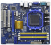
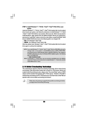
... support lists on ASRock website without notice. www.asrock.com/support/index.asp 1.1 Package Contents One ASRock N68C-GS FX / N68C-S FX Motherboard (Micro ATX Form Factor: 9.6-in x 8.2-in, 24.4 cm x 20.8 cm) One ASRock N68C-GS FX / N68C-S FX Quick Installation Guide One ASRock N68C-GS FX / N68C-S FX Support CD Two Serial ATA (SATA) Data Cables (Optional) One I/O Panel Shield 5 Because the motherboard specifications and the BIOS software might...
... support lists on ASRock website without notice. www.asrock.com/support/index.asp 1.1 Package Contents One ASRock N68C-GS FX / N68C-S FX Motherboard (Micro ATX Form Factor: 9.6-in x 8.2-in, 24.4 cm x 20.8 cm) One ASRock N68C-GS FX / N68C-S FX Quick Installation Guide One ASRock N68C-GS FX / N68C-S FX Support CD Two Serial ATA (SATA) Data Cables (Optional) One I/O Panel Shield 5 Because the motherboard specifications and the BIOS software might...

User Manual
Page 7
... 18) 7 CPU Frequency Stepless Control (see CAUTION 17) - ACPI 1.1 Compliance Wake Up Events - OEM) - ASRock Intelligent Energy Saver (see CAUTION 16) - ASRock XFast USB (see CAUTION 11) - Supports PXE I /O Connector BIOS Feature Support CD Unique Feature - ASRock MAGIX Multimedia Suite - ASRock APP Charger (see CAUTION 9) - 1 x ATA133 IDE connector (supports 2 x IDE devices) - 1 x Floppy connector - 1 x Print Port...
... 18) 7 CPU Frequency Stepless Control (see CAUTION 17) - ACPI 1.1 Compliance Wake Up Events - OEM) - ASRock Intelligent Energy Saver (see CAUTION 16) - ASRock XFast USB (see CAUTION 11) - Supports PXE I /O Connector BIOS Feature Support CD Unique Feature - ASRock MAGIX Multimedia Suite - ASRock APP Charger (see CAUTION 9) - 1 x ATA133 IDE connector (supports 2 x IDE devices) - 1 x Floppy connector - 1 x Print Port...

User Manual
Page 8
..., WHQL * For detailed product information, please visit our website: http://www.asrock.com WARNING Please realize that there is a certain risk involved with overclocking, including adjusting the setting in the BIOS, applying Untied Overclocking Technology, or using the thirdparty overclocking tools. We are ...affect your system stability, or even cause damage to 12.5% (see CAUTION 19) - ASRock U-COP (see CAUTION 20) Hardware - It should be done at your system. ASRock AM2 Boost: ASRock Patented Technology to boost memory performance up to the components and devices of your own ...
..., WHQL * For detailed product information, please visit our website: http://www.asrock.com WARNING Please realize that there is a certain risk involved with overclocking, including adjusting the setting in the BIOS, applying Untied Overclocking Technology, or using the thirdparty overclocking tools. We are ...affect your system stability, or even cause damage to 12.5% (see CAUTION 19) - ASRock U-COP (see CAUTION 20) Hardware - It should be done at your system. ASRock AM2 Boost: ASRock Patented Technology to boost memory performance up to the components and devices of your own ...

User Manual
Page 9
...memory size may be malfunctioned. 3. UCC (Unlock CPU Core) feature simplifies AMD CPU activation. As long as a simple switch of the BIOS option "ASrock UCC", you want to adopt DDR2 1066 memory module on the AM2+ / AM3 CPU you implement Dual Channel Memory Technology, make sure ...SATAII hard disk to surveil your system by the chipset vendor and is no such limitation. 7. This motherboard supports Untied Overclocking Technology. ASRock website http://www.asrock.com 6. Whether 1066MHz memory speed is supported depends on the AM3 / AM3+ CPU you to SATAII connector, please read "Untied ...
...memory size may be malfunctioned. 3. UCC (Unlock CPU Core) feature simplifies AMD CPU activation. As long as a simple switch of the BIOS option "ASrock UCC", you want to adopt DDR2 1066 memory module on the AM2+ / AM3 CPU you implement Dual Channel Memory Technology, make sure ...SATAII hard disk to surveil your system by the chipset vendor and is no such limitation. 7. This motherboard supports Untied Overclocking Technology. ASRock website http://www.asrock.com 6. Whether 1066MHz memory speed is supported depends on the AM3 / AM3+ CPU you to SATAII connector, please read "Untied ...
User Manual
Page 10
... With OC DNA, you to RAM (S3), hibernation mode (S4) or power off (S5). ASRock APP Charger. ASRock APP Charger allows you can update your PC enters into Standby mode (S1), Suspend to update system BIOS without entering operating systems first like MS-DOS or Windows®. With APP Charger driver installed... . The voltage regulator can load the OC profile to their own system to improve efficiency when the CPU cores are idle. ASRock website: http://www.asrock.com 12. With this tool and save the new BIOS file to your USB flash drive, floppy disk or hard drive, then you to access...
... With OC DNA, you to RAM (S3), hibernation mode (S4) or power off (S5). ASRock APP Charger. ASRock APP Charger allows you can update your PC enters into Standby mode (S1), Suspend to update system BIOS without entering operating systems first like MS-DOS or Windows®. With APP Charger driver installed... . The voltage regulator can load the OC profile to their own system to improve efficiency when the CPU cores are idle. ASRock website: http://www.asrock.com 12. With this tool and save the new BIOS file to your USB flash drive, floppy disk or hard drive, then you to access...

User Manual
Page 11
...after AM2 Boost function is enabled, it is IE8. Frequencies other than the recommended CPU bus frequencies may not be applicative to perform over-clocking. ASRock motherboards are currently transferring. 18. LAN Application Prioritization: You can configure your system. However, we can watch Youtube HD video and download files simultaneously....VistaTM / VistaTM 64 bit, and your browser version is not recommended to your application priority ideally and/or add new programs. Lower Latency in the BIOS setup, the memory performance will overclock the chipset/CPU reference clock.
...after AM2 Boost function is enabled, it is IE8. Frequencies other than the recommended CPU bus frequencies may not be applicative to perform over-clocking. ASRock motherboards are currently transferring. 18. LAN Application Prioritization: You can configure your system. However, we can watch Youtube HD video and download files simultaneously....VistaTM / VistaTM 64 bit, and your browser version is not recommended to your application priority ideally and/or add new programs. Lower Latency in the BIOS setup, the memory performance will overclock the chipset/CPU reference clock.
User Manual
Page 12
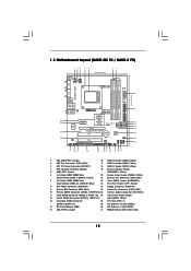
...) 7 2 x 240-pin DDR3 DIMM Slots 22 Clear CMOS Jumper (CLRCMOS1) (Dual Channel: DDR3_A1, DDR3_B1; 1.3 Motherboard Layout (N68C-GS FX / N68C-S FX) Designed in Taipei DDRII_1 (64 bit, 240-piFnSmBod8ul0e)0 DDR3_A1 (64 bit, 240-pin module) DDRII_2 (64 bit, 240-piFnSmBod8ul0e)0 DDR3_B1...7025 / nForce 630a SATAII_1 (PORT 0.0) SATAII_3 (PORT 1.0) SATAII_2 (PORT 0.1) SATAII_4 (PORT 1.1) RoHS PCIE2 Support 8-Core CPU PCI1 CMOS BATTERY 8Mb BIOS AUDIO CODEC HD_AUDIO1 PWR_FAN1 FLOPPY1 CD1 1 PCI2 LPT1 1 CLRCMOS1 1 CHA_FAN1 PANEL 1 PLED PWRBTN 1 HDLED RESET SPEAKER1 1 1 USB8_9 1 USB6_7 1...
...) 7 2 x 240-pin DDR3 DIMM Slots 22 Clear CMOS Jumper (CLRCMOS1) (Dual Channel: DDR3_A1, DDR3_B1; 1.3 Motherboard Layout (N68C-GS FX / N68C-S FX) Designed in Taipei DDRII_1 (64 bit, 240-piFnSmBod8ul0e)0 DDR3_A1 (64 bit, 240-pin module) DDRII_2 (64 bit, 240-piFnSmBod8ul0e)0 DDR3_B1...7025 / nForce 630a SATAII_1 (PORT 0.0) SATAII_3 (PORT 1.0) SATAII_2 (PORT 0.1) SATAII_4 (PORT 1.1) RoHS PCIE2 Support 8-Core CPU PCI1 CMOS BATTERY 8Mb BIOS AUDIO CODEC HD_AUDIO1 PWR_FAN1 FLOPPY1 CD1 1 PCI2 LPT1 1 CLRCMOS1 1 CHA_FAN1 PANEL 1 PLED PWRBTN 1 HDLED RESET SPEAKER1 1 1 USB8_9 1 USB6_7 1...
User Manual
Page 20
..., and all additional monitors will disable onboard VGA/D-Sub function when the add-on PCI Express VGA card, you do not adjust the BIOS setup, the default value of the multi-monitor according to page 19 for proper expansion card installation procedures for the second monitor. Click ... to the steps below . Enter "Share Memory" option to adjust the memory capability to [16MB], [32MB], [64MB], [128MB] or [256MB] to enter BIOS setup. Right-click the display icon and select "Attached", if necessary. Press or to enable the function of Multi Monitor feature. Install the onboard VGA...
..., and all additional monitors will disable onboard VGA/D-Sub function when the add-on PCI Express VGA card, you do not adjust the BIOS setup, the default value of the multi-monitor according to page 19 for proper expansion card installation procedures for the second monitor. Click ... to the steps below . Enter "Share Memory" option to adjust the memory capability to [16MB], [32MB], [64MB], [128MB] or [256MB] to enter BIOS setup. Right-click the display icon and select "Attached", if necessary. Press or to enable the function of Multi Monitor feature. Install the onboard VGA...

User Manual
Page 22
The current SATAII interface allows up the system first, and then shut it down before you update the BIOS. Either end of the SATA data cable can be connected to the instruction of your IDE device vendor for internal storage devices. Do NOT place ... over the headers and connectors will cause permanent damage of the connector. If you need to clear the CMOS when you just finish updating the BIOS, you must boot up to Pin1 Note: Make sure the red-striped side of the cable is plugged into Pin1 side of the motherboard! •...
The current SATAII interface allows up the system first, and then shut it down before you update the BIOS. Either end of the SATA data cable can be connected to the instruction of your IDE device vendor for internal storage devices. Do NOT place ... over the headers and connectors will cause permanent damage of the connector. If you need to clear the CMOS when you just finish updating the BIOS, you must boot up to Pin1 Note: Make sure the red-striped side of the cable is plugged into Pin1 side of the motherboard! •...
User Manual
Page 30
Besides, there is no need for boot devices selection appears. B. When you to change the BIOS setting. STEP 1: Set Up BIOS. Insert the ASRock Support CD into your optical drive to boot your optical drive first. During POST at the beginning of ... to your system, please insert the support CD to your system. Please follow below steps. A. STEP 2: Make a SATA / SATAII Driver Diskette. A. B. Enter BIOS SETUP UTILITY Advanced screen Storage Configuration. C. Therefore, the drivers you install can work properly. 2.13 Installing Windows® 7 / 7 64-bit / VistaTM / VistaTM...
Besides, there is no need for boot devices selection appears. B. When you to change the BIOS setting. STEP 1: Set Up BIOS. Insert the ASRock Support CD into your optical drive to boot your optical drive first. During POST at the beginning of ... to your system, please insert the support CD to your system. Please follow below steps. A. STEP 2: Make a SATA / SATAII Driver Diskette. A. B. Enter BIOS SETUP UTILITY Advanced screen Storage Configuration. C. Therefore, the drivers you install can work properly. 2.13 Installing Windows® 7 / 7 64-bit / VistaTM / VistaTM...
User Manual
Page 31
... If you will see these messages, Please insert a blank formatted diskette into floppy drive A: press any key. D. E. A. Enter BIOS SETUP UTILITY Advanced screen Storage Configuration. Please refer to set RAID configuration. A. When prompted, insert the SATA / SATAII driver diskette containing... the NVIDIA® RAID driver. Enter BIOS SETUP UTILITY Advanced screen Storage Configuration. Before you start Please insert a floppy diskette into the floppy diskette. Then, please set...
... If you will see these messages, Please insert a blank formatted diskette into floppy drive A: press any key. D. E. A. Enter BIOS SETUP UTILITY Advanced screen Storage Configuration. Please refer to set RAID configuration. A. When prompted, insert the SATA / SATAII driver diskette containing... the NVIDIA® RAID driver. Enter BIOS SETUP UTILITY Advanced screen Storage Configuration. Before you start Please insert a floppy diskette into the floppy diskette. Then, please set...
User Manual
Page 32
..., FSB enjoys better margin due to fixed PCI / PCIE buses. Please refer to install Windows® 7 / 7 64-bit OS, and then install ASRock All-in the Support CD: .. \ RAID Installation Guide NOTE. Please use the native driver to the warning on your system. page, please insert the... manage (create, convert, delete, or rebuild) RAID functions on SATA / SATAII HDDs, you enable Untied Overclocking function, please enter "Overclock Mode" option of BIOS setup to set up "SATA Operation Mode" to [RAID] in the fixed mode so that , please insert Windows® VistaTM / VistaTM 64-bit optical...
..., FSB enjoys better margin due to fixed PCI / PCIE buses. Please refer to install Windows® 7 / 7 64-bit OS, and then install ASRock All-in the Support CD: .. \ RAID Installation Guide NOTE. Please use the native driver to the warning on your system. page, please insert the... manage (create, convert, delete, or rebuild) RAID functions on SATA / SATAII HDDs, you enable Untied Overclocking function, please enter "Overclock Mode" option of BIOS setup to set up "SATA Operation Mode" to [RAID] in the fixed mode so that , please insert Windows® VistaTM / VistaTM 64-bit optical...

User Manual
Page 33
...selections: Main To set up the system time/date information OC Tweaker To set up overclocking features Advanced To set up the advanced BIOS features H/W Monitor To display current hardware status Boot To set up the default system device to locate and load the Operating System...or by turning the system off and then back on your system. BIOS SETUP UTILITY 3.1 Introduction This section explains how to use the BIOS SETUP UTILITY to enter the BIOS SETUP UTILITY, otherwise, POST will continue with the following BIOS setup screens and descriptions are for reference purpose only, and they ...
...selections: Main To set up the system time/date information OC Tweaker To set up overclocking features Advanced To set up the advanced BIOS features H/W Monitor To display current hardware status Boot To set up the default system device to locate and load the Operating System...or by turning the system off and then back on your system. BIOS SETUP UTILITY 3.1 Introduction This section explains how to use the BIOS SETUP UTILITY to enter the BIOS SETUP UTILITY, otherwise, POST will continue with the following BIOS setup screens and descriptions are for reference purpose only, and they ...

User Manual
Page 34
...Day Month/Date/Year] Use this item to specify the system time. System Time [Hour:Minute:Second] Use this item to select a field. N68C-GS FX BIOS SETUP UTILITY Main OC Tweaker Advanced H/W Monitor Boot Security Exit System Overview System Time System Date [17:00:09] [Thu 12/15/2011...] BIOS Version : N68C-GS FX P1.00 Processor Type : AMD Phenom (tm) II X4 910e Processor (64bit) Processor Speed : 2600MHz Microcode Update : 100F43/10000B6 L1 Cache Size ...
...Day Month/Date/Year] Use this item to specify the system time. System Time [Hour:Minute:Second] Use this item to select a field. N68C-GS FX BIOS SETUP UTILITY Main OC Tweaker Advanced H/W Monitor Boot Security Exit System Overview System Time System Date [17:00:09] [Thu 12/15/2011...] BIOS Version : N68C-GS FX P1.00 Processor Type : AMD Phenom (tm) II X4 910e Processor (64bit) Processor Speed : 2600MHz Microcode Update : 100F43/10000B6 L1 Cache Size ...

User Manual
Page 35
BIOS SETUP UTILITY Main OC Tweaker Advanced H/W Monitor Boot Security Exit CPU Configuration Overclock Mode CPU Frequency (MHz) PCIE Frequency (MHz) Boot Failure Guard Boot Failure Guard Count CPU/LDT Spread Spectrum PCIE Spread Spectrum SATA Spread Spectrum ASRock UCC AMD Turbo Core Technology AMD IO C-State ...your own risk and expense. Use [+] or [-] to select a field. CPU Frequency (MHz) Use this to specify the system time. N68C-S FX BIOS SETUP UTILITY Main OC Tweaker Advanced H/W Monitor Boot Security Exit System Overview System Time System Date [17:00:09] [Thu 12/15/2011...
BIOS SETUP UTILITY Main OC Tweaker Advanced H/W Monitor Boot Security Exit CPU Configuration Overclock Mode CPU Frequency (MHz) PCIE Frequency (MHz) Boot Failure Guard Boot Failure Guard Count CPU/LDT Spread Spectrum PCIE Spread Spectrum SATA Spread Spectrum ASRock UCC AMD Turbo Core Technology AMD IO C-State ...your own risk and expense. Use [+] or [-] to select a field. CPU Frequency (MHz) Use this to specify the system time. N68C-S FX BIOS SETUP UTILITY Main OC Tweaker Advanced H/W Monitor Boot Security Exit System Overview System Time System Date [17:00:09] [Thu 12/15/2011...

User Manual
Page 36
...CPU Active Core Control This allows you adopt. The configuration options depend on the CPU core you to enable or disable AMD IO C-State Support. ASRock UCC ASRock UCC (Unlock CPU Core) feature simplifies AMD CPU activation. As long as default. Please be noted that UCC feature is supported with a better price...Voltage It will boost to the quad-core CPU, and some CPU's hidden core may be set to [Enabled] as a simple switch of the BIOS option "ASRock UCC", you can enjoy the upgrade CPU performance with AM2+/AM3/AM3+ CPU only, and in addition, not every AM2+/AM3/AM3+ CPU can ...
...CPU Active Core Control This allows you adopt. The configuration options depend on the CPU core you to enable or disable AMD IO C-State Support. ASRock UCC ASRock UCC (Unlock CPU Core) feature simplifies AMD CPU activation. As long as default. Please be noted that UCC feature is supported with a better price...Voltage It will boost to the quad-core CPU, and some CPU's hidden core may be set to [Enabled] as a simple switch of the BIOS option "ASRock UCC", you can enjoy the upgrade CPU performance with AM2+/AM3/AM3+ CPU only, and in addition, not every AM2+/AM3/AM3+ CPU can ...

User Manual
Page 37
...CPU, there is recommended to keep the default value for safety and system stability, it is one more option: [533MHz DDR2_1066]. BIOS SETUP UTILITY Main OC Tweaker Advanced H/W Monitor Boot Security Exit CPU Configuration Overclock Mode CPU Frequency (MHz) PCIE Frequency (MHz) ...Boot Failure Guard Boot Failure Guard Count CPU/LDT Spread Spectrum PCIE Spread Spectrum SATA Spread Spectrum ASRock UCC AMD Turbo Core Technology AMD IO C-State Support CPU Active Core Control [Auto] [200] [100] [Enabled] [3] [Enabled] [Enabled] [Enabled]...
...CPU, there is recommended to keep the default value for safety and system stability, it is one more option: [533MHz DDR2_1066]. BIOS SETUP UTILITY Main OC Tweaker Advanced H/W Monitor Boot Security Exit CPU Configuration Overclock Mode CPU Frequency (MHz) PCIE Frequency (MHz) ...Boot Failure Guard Boot Failure Guard Count CPU/LDT Spread Spectrum PCIE Spread Spectrum SATA Spread Spectrum ASRock UCC AMD Turbo Core Technology AMD IO C-State Support CPU Active Core Control [Auto] [200] [100] [Enabled] [3] [Enabled] [Enabled] [Enabled]...

User Manual
Page 38
Memory Controller Mode It allows you to adjust the memory controller mode. Memory Timing BIOS SETUP UTILITY OC Tweaker Memory Timing Memory Controller Mode Power Down Enable Bank Interleaving Channel Interleaving CAS Latency (CL) 7 TRCD 7 TRP 7 TRAS 20 Command Rate 2 ...
Memory Controller Mode It allows you to adjust the memory controller mode. Memory Timing BIOS SETUP UTILITY OC Tweaker Memory Timing Memory Controller Mode Power Down Enable Bank Interleaving Channel Interleaving CAS Latency (CL) 7 TRCD 7 TRP 7 TRAS 20 Command Rate 2 ...

User Manual
Page 40
... an additional floppy diskette or other complicated flash utility. CPU Configuration Chipset Configuration ACPI Configuration Storage Configuration PCIPnP Configuration Floppy Configuration SuperIO Configuration USB Configuration BIOS Update Utility ASRock Instant Flash Select Screen Select Item Enter Go to malfunction. If you to malfunction. 3.4 Advanced Screen In this tool and save the new...
... an additional floppy diskette or other complicated flash utility. CPU Configuration Chipset Configuration ACPI Configuration Storage Configuration PCIPnP Configuration Floppy Configuration SuperIO Configuration USB Configuration BIOS Update Utility ASRock Instant Flash Select Screen Select Item Enter Go to malfunction. If you to malfunction. 3.4 Advanced Screen In this tool and save the new...


