User Manual
Page 3
...Expansion Slots (PCI and PCI Express Slots 17 2.5 Easy Multi Monitor Feature 18 2.6 Jumpers Setup 19 2.7 Onboard Headers and Connectors 20 2.8 SATAII Hard Disk Setup Guide 24 2.9 Serial ATA (SATA) / Serial ATAII (SATAII)... 28 2.15 Untied Overclocking Technology 29 3 . Contents 1 . Introduction 5 1.1 Package Contents 5 1.2 Specifications 6 1.3 Motherboard Layout (N68-VGS3 FX / N68-VS3 FX 11 1.4 I/O Panel (N68-VGS3 FX 12 1.5 I/O Panel (N68-VS3 FX 13 2 . BIOS SETUP UTILITY 30 3.1 Introduction 30 3.1.1 BIOS Menu Bar 30 3.1.2 Navigation Keys 31 3.2 Main Screen 31 3.3 OC...
...Expansion Slots (PCI and PCI Express Slots 17 2.5 Easy Multi Monitor Feature 18 2.6 Jumpers Setup 19 2.7 Onboard Headers and Connectors 20 2.8 SATAII Hard Disk Setup Guide 24 2.9 Serial ATA (SATA) / Serial ATAII (SATAII)... 28 2.15 Untied Overclocking Technology 29 3 . Contents 1 . Introduction 5 1.1 Package Contents 5 1.2 Specifications 6 1.3 Motherboard Layout (N68-VGS3 FX / N68-VS3 FX 11 1.4 I/O Panel (N68-VGS3 FX 12 1.5 I/O Panel (N68-VS3 FX 13 2 . BIOS SETUP UTILITY 30 3.1 Introduction 30 3.1.1 BIOS Menu Bar 30 3.1.2 Navigation Keys 31 3.2 Main Screen 31 3.3 OC...
User Manual
Page 7
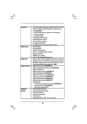
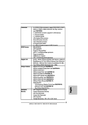
... 5, JBOD), NCQ and "Hot Plug" functions (see CAUTION 19) - Front panel audio header - 2 x USB 2.0 headers (support 4 USB 2.0 ports) - 8Mb AMI BIOS - CPU/Chassis FAN connector - 24 pin ATX power connector - 4 pin 12V power connector - SMBIOS 2.3.1 Support - Drivers, Utilities, AntiVirus Software (Trial Version), CyberLink MediaEspresso 6.5 Trial, ASRock Software Suite (CyberLink DVD Suite - CPU Temperature Sensing...
... 5, JBOD), NCQ and "Hot Plug" functions (see CAUTION 19) - Front panel audio header - 2 x USB 2.0 headers (support 4 USB 2.0 ports) - 8Mb AMI BIOS - CPU/Chassis FAN connector - 24 pin ATX power connector - 4 pin 12V power connector - SMBIOS 2.3.1 Support - Drivers, Utilities, AntiVirus Software (Trial Version), CyberLink MediaEspresso 6.5 Trial, ASRock Software Suite (CyberLink DVD Suite - CPU Temperature Sensing...
User Manual
Page 11
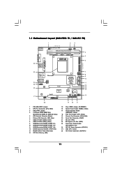
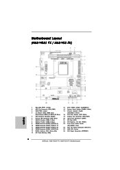
1.3 Motherboard Layout (N68-VGS3 FX / N68-VS3 FX) 26 USB 2.0 T: USB2 B: USB3 VGA1 PS2 Mouse PS2 Keyboard 1 2 3 17.8cm (7.0-in) Support 8-Core CPU 1 PS2_USB_PWR1 CPU_FAN1 1 USB_PWR2 DDR3_B1 (64 bit, 240-FpSin Bm8od0u0le) 4 DDR3_A1 (... NVIDIA GeForce 7025 / nForce 630a 14 SPI Flash Memory (4Mb) 19 18 17 15 Clear CMOS Jumper (CLRCMOS1) 16 System Panel Header (PANEL1, White) 17 Chassis Speaker Header (SPEAKER 1, White) 18 Print Port Header (LPT1, White) 19 Chassis Fan Connector (CHA_FAN1) 20 Serial Port Connector (COM1) 21 PCI Slot (PCI1) 22 PCI Express x16...
1.3 Motherboard Layout (N68-VGS3 FX / N68-VS3 FX) 26 USB 2.0 T: USB2 B: USB3 VGA1 PS2 Mouse PS2 Keyboard 1 2 3 17.8cm (7.0-in) Support 8-Core CPU 1 PS2_USB_PWR1 CPU_FAN1 1 USB_PWR2 DDR3_B1 (64 bit, 240-FpSin Bm8od0u0le) 4 DDR3_A1 (... NVIDIA GeForce 7025 / nForce 630a 14 SPI Flash Memory (4Mb) 19 18 17 15 Clear CMOS Jumper (CLRCMOS1) 16 System Panel Header (PANEL1, White) 17 Chassis Speaker Header (SPEAKER 1, White) 18 Print Port Header (LPT1, White) 19 Chassis Fan Connector (CHA_FAN1) 20 Serial Port Connector (COM1) 21 PCI Slot (PCI1) 22 PCI Express x16...
User Manual
Page 12
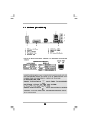
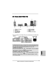
... the left side on your change . Please refer to the table below instructions according to the OS you need to connect a front panel audio cable to the front panel audio header. 1 . 4 I/O Panel (N68-VGS3 FX) 1 2 3 4 5 9 8 1 PS/2 Mouse Port (Green) * 2 RJ-45 Port 3 Line In (Light Blue) 4 Front Speaker (Lime) 5 Microphone (Pink) 7 6 6 USB 2.0 Ports (USB01) 7 USB 2.0 Ports (USB23...
... the left side on your change . Please refer to the table below instructions according to the OS you need to connect a front panel audio cable to the front panel audio header. 1 . 4 I/O Panel (N68-VGS3 FX) 1 2 3 4 5 9 8 1 PS/2 Mouse Port (Green) * 2 RJ-45 Port 3 Line In (Light Blue) 4 Front Speaker (Lime) 5 Microphone (Pink) 7 6 6 USB 2.0 Ports (USB01) 7 USB 2.0 Ports (USB23...
User Manual
Page 13
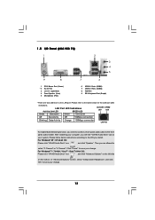
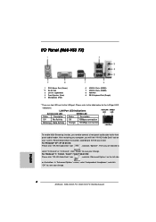
...click "VIA HD Audio Deck" icon , and click "Speaker". Then you need to connect a front panel audio cable to the front panel audio header. LAN Port LED Indications Activity/Link LED SPEED LED ACT/LINK SPEED LED LED Status Description Status Description... to the LAN port. After restarting your change . Please refer to save your computer, you install. Please follow below for the LAN port LED indications. 1 . 5 I/O Panel (N68-VS3 FX) 1 2 3 4 5 9 8 1 PS/2 Mouse Port (Green) * 2 RJ-45 Port 3 Line In (Light Blue) 4 Front Speaker (Lime) 5 Microphone (Pink) 7 6 6 USB...
...click "VIA HD Audio Deck" icon , and click "Speaker". Then you need to connect a front panel audio cable to the front panel audio header. LAN Port LED Indications Activity/Link LED SPEED LED ACT/LINK SPEED LED LED Status Description Status Description... to the LAN port. After restarting your change . Please refer to save your computer, you install. Please follow below for the LAN port LED indications. 1 . 5 I/O Panel (N68-VS3 FX) 1 2 3 4 5 9 8 1 PS/2 Mouse Port (Green) * 2 RJ-45 Port 3 Line In (Light Blue) 4 Front Speaker (Lime) 5 Microphone (Pink) 7 6 6 USB...
User Manual
Page 21
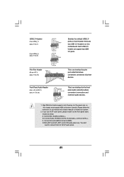
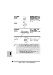
...No. 23) GND PRESENCE# MIC_RET OUT_RET 1 OUT2_L J_SENSE OUT2_R MIC2_R MIC2_L This is an interface for the front panel audio cable that allows convenient connection of audio devices. 1. B. Front Panel Audio Header (9-pin HD_AUDIO1) (see p.11 No. 18) AFD# ERROR# PINIT# SLIN# GND 1 SPD7 SPD6 ACK#...support HDA to function correctly. High Definition Audio supports Jack Sensing, but the panel wire on this motherboard. Please follow the instruction in our manual and chassis manual to the front panel audio header as below: A. Connect Audio_R (RIN) to OUT2_R and Audio_L (LIN) to...
...No. 23) GND PRESENCE# MIC_RET OUT_RET 1 OUT2_L J_SENSE OUT2_R MIC2_R MIC2_L This is an interface for the front panel audio cable that allows convenient connection of audio devices. 1. B. Front Panel Audio Header (9-pin HD_AUDIO1) (see p.11 No. 18) AFD# ERROR# PINIT# SLIN# GND 1 SPD7 SPD6 ACK#...support HDA to function correctly. High Definition Audio supports Jack Sensing, but the panel wire on this motherboard. Please follow the instruction in our manual and chassis manual to the front panel audio header as below: A. Connect Audio_R (RIN) to OUT2_R and Audio_L (LIN) to...
User Manual
Page 22
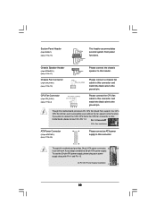
... No. 19) PLED+ PLEDPWRBTN# GND 1 DUMMY RESET# GND HDLEDHDLED+ 1 SPEAKER DUMMY DUMMY +5V This header accommodates several system front panel functions. If you adopt a traditional 20-pin ATX power supply. System Panel Header (9-pin PANEL1) (see p.11 No. 16) Chassis Speaker Header (4-pin SPEAKER 1) (see p.11 No. 17) Chassis Fan Connector (3-pin CHA_FAN1) (see p.11... speaker to this motherboard, please connect it can work if you plan to connect the 3-Pin CPU fan to the CPU fan connector on this header.
... No. 19) PLED+ PLEDPWRBTN# GND 1 DUMMY RESET# GND HDLEDHDLED+ 1 SPEAKER DUMMY DUMMY +5V This header accommodates several system front panel functions. If you adopt a traditional 20-pin ATX power supply. System Panel Header (9-pin PANEL1) (see p.11 No. 16) Chassis Speaker Header (4-pin SPEAKER 1) (see p.11 No. 17) Chassis Fan Connector (3-pin CHA_FAN1) (see p.11... speaker to this motherboard, please connect it can work if you plan to connect the 3-Pin CPU fan to the CPU fan connector on this header.
Quick Installation Guide
Page 2
... Speaker Header (SPEAKER 1, White) 18 Print Port Header (LPT1, White) 19 Chassis Fan Connector (CHA_FAN1) 20 Serial Port Connector (COM1) 21 PCI Slot (PCI1) 22 PCI Express x16 Slot (PCIE1) 23 Front Panel Audio Header (HD_AUDIO1, Lime) 24 ATX 12V Power Connector (ATX12V1) 25 AM3 CPU Socket 26 ATX Power Connector (ATXPWR1) 2 ASRock N68-VGS3 FX / N68-VS3 FX Motherboard...
... Speaker Header (SPEAKER 1, White) 18 Print Port Header (LPT1, White) 19 Chassis Fan Connector (CHA_FAN1) 20 Serial Port Connector (COM1) 21 PCI Slot (PCI1) 22 PCI Express x16 Slot (PCIE1) 23 Front Panel Audio Header (HD_AUDIO1, Lime) 24 ATX 12V Power Connector (ATX12V1) 25 AM3 CPU Socket 26 ATX Power Connector (ATXPWR1) 2 ASRock N68-VGS3 FX / N68-VS3 FX Motherboard...
Quick Installation Guide
Page 3
..., and click "Advanced Options" on the left side on your computer, you need to connect a front panel audio cable to the front panel audio header. LAN Port LED Indications Activity/Link LED SPEED LED ACT/LINK SPEED LED LED Status Description Status Description Off...click "OK" to save your change . Click "Power" to save your change . 3 ASRock N68-VGS3 FX / N68-VS3 FX Motherboard English For Windows® XP / XP 64-bit OS: Please click "VIA HD Audio Deck" icon , and click "Speaker". I/O Panel (N68-VGS3 FX) 1 PS/2 Mouse Port (Green) * 2 RJ-45 Port 3 Line In (Light...
..., and click "Advanced Options" on the left side on your computer, you need to connect a front panel audio cable to the front panel audio header. LAN Port LED Indications Activity/Link LED SPEED LED ACT/LINK SPEED LED LED Status Description Status Description Off...click "OK" to save your change . Click "Power" to save your change . 3 ASRock N68-VGS3 FX / N68-VS3 FX Motherboard English For Windows® XP / XP 64-bit OS: Please click "VIA HD Audio Deck" icon , and click "Speaker". I/O Panel (N68-VGS3 FX) 1 PS/2 Mouse Port (Green) * 2 RJ-45 Port 3 Line In (Light...
Quick Installation Guide
Page 4
.... After restarting your computer, you need to connect a front panel audio cable to save your change . 4 ASRock N68-VGS3 FX / N68-VS3 FX Motherboard English Please follow below for the LAN port LED indications. Click "Power" to save your system. I/O Panel (N68-VS3 FX) 1 PS/2 Mouse Port (Green) * 2 RJ-45 ...side on your change . In "Advanced Options" screen, select "Independent Headphone", and click "OK" to the front panel audio header. LAN Port LED Indications Activity/Link LED SPEED LED ACT/LINK SPEED LED LED Status Description Status Description Off No ...
.... After restarting your computer, you need to connect a front panel audio cable to save your change . 4 ASRock N68-VGS3 FX / N68-VS3 FX Motherboard English Please follow below for the LAN port LED indications. Click "Power" to save your system. I/O Panel (N68-VS3 FX) 1 PS/2 Mouse Port (Green) * 2 RJ-45 ...side on your change . In "Advanced Options" screen, select "Independent Headphone", and click "OK" to the front panel audio header. LAN Port LED Indications Activity/Link LED SPEED LED ACT/LINK SPEED LED LED Status Description Status Description Off No ...
Quick Installation Guide
Page 7
... CAUTION 15) - Hybrid Booster: - Voltage Monitoring: +12V, +5V, +3.3V, Vcore English 7 ASRock N68-VGS3 FX / N68-VS3 FX Motherboard CPU/Chassis FAN connector - 24 pin ATX power connector - 4 pin 12V power connector - Front panel audio header - 2 x USB 2.0 headers (support 4 USB 2.0 ports) - 8Mb AMI BIOS - ASRock SmartView (see CAUTION 14) - ASRock U-COP (see CAUTION 10) - CPU Fan Tachometer - CPU Temperature Sensing - Supports...
... CAUTION 15) - Hybrid Booster: - Voltage Monitoring: +12V, +5V, +3.3V, Vcore English 7 ASRock N68-VGS3 FX / N68-VS3 FX Motherboard CPU/Chassis FAN connector - 24 pin ATX power connector - 4 pin 12V power connector - Front panel audio header - 2 x USB 2.0 headers (support 4 USB 2.0 ports) - 8Mb AMI BIOS - ASRock SmartView (see CAUTION 14) - ASRock U-COP (see CAUTION 10) - CPU Fan Tachometer - CPU Temperature Sensing - Supports...
Quick Installation Guide
Page 18
...) to MIC2_L. MIC_RET and OUT_RET are two USB 2.0 headers on this motherboard. English 18 ASRock N68-VGS3 FX / N68-VS3 FX Motherboard High Definition Audio supports Jack Sensing, but the panel wire on the chassis must support HDA to the front panel audio header as below: A. If you use AC'97 audio panel, please install it to function correctly. You don...
...) to MIC2_L. MIC_RET and OUT_RET are two USB 2.0 headers on this motherboard. English 18 ASRock N68-VGS3 FX / N68-VS3 FX Motherboard High Definition Audio supports Jack Sensing, but the panel wire on the chassis must support HDA to the front panel audio header as below: A. If you use AC'97 audio panel, please install it to function correctly. You don...

Quick Installation Guide
Page 19
... ATX Power Supply Installation 1 13 English 19 ASRock N68-VGS3 FX / N68-VS3 FX Motherboard Chassis Fan Connector (3-pin CHA_FAN1) (see p.2 No. 26) 12 24 Please connect an ATX power supply to Pin 1-3. Though this header. Chassis Speaker Header (4-pin SPEAKER 1) (see p.2 No. 16) This header accommodates several system front panel functions. System Panel Header (9-pin PANEL1) (see p.2 No. 17) Please connect...
... ATX Power Supply Installation 1 13 English 19 ASRock N68-VGS3 FX / N68-VS3 FX Motherboard Chassis Fan Connector (3-pin CHA_FAN1) (see p.2 No. 26) 12 24 Please connect an ATX power supply to Pin 1-3. Though this header. Chassis Speaker Header (4-pin SPEAKER 1) (see p.2 No. 16) This header accommodates several system front panel functions. System Panel Header (9-pin PANEL1) (see p.2 No. 17) Please connect...


