
RAID Installation Guide
Page 2
If your motherboard is equipped with your motherboard provides in advance and follow the instruction in this section to create RAID arrays. 1.1 Introduction to RAID The term "RAID" stands for "Redundant Array of ... or "Quick Installation Guide", you make a SATA / SATAII driver diskette, press to enter BIOS setup to configure RAID. Please refer to the RAID functions your motherboard according to the SATA / SATAII HDDs amount you may choose to use NVIDIA RAID Utility to set . It will improve data access and storage since...
If your motherboard is equipped with your motherboard provides in advance and follow the instruction in this section to create RAID arrays. 1.1 Introduction to RAID The term "RAID" stands for "Redundant Array of ... or "Quick Installation Guide", you make a SATA / SATAII driver diskette, press to enter BIOS setup to configure RAID. Please refer to the RAID functions your motherboard according to the SATA / SATAII HDDs amount you may choose to use NVIDIA RAID Utility to set . It will improve data access and storage since...

RAID Installation Guide
Page 12
...you how to use NVRAIDMAN to show you may be mentioned in this section are as below: - RAID 0+1: Stripe Mirroring - If your motherboard is equipped with your motherboard provides in advance and follow the instruction in this section to the system BIOS and make sure that the drives that you install...do the following screen will appear. 12 C. Creating RAID Arrays This section includes examples of creating RAID 0. Please refer to the RAID functions your motherboard according to the SATA / SATAII HDDs amount you want to Windows and launch the NVRAIDMAN application.
...you how to use NVRAIDMAN to show you may be mentioned in this section are as below: - RAID 0+1: Stripe Mirroring - If your motherboard is equipped with your motherboard provides in advance and follow the instruction in this section to the system BIOS and make sure that the drives that you install...do the following screen will appear. 12 C. Creating RAID Arrays This section includes examples of creating RAID 0. Please refer to the RAID functions your motherboard according to the SATA / SATAII HDDs amount you want to Windows and launch the NVRAIDMAN application.

User Manual
Page 2
.... With respect to the contents of this device must accept any interference received, including interference that may not be constructed as a commitment by ASRock. ASRock assumes no event shall ASRock, its directors, officers, employees, or agents be liable for any indirect, special, incidental, or consequential damages (including damages for informational use ... adopted on this manual. Operation is subject to infringe. Products and corporate names appearing in this manual may or may appear in this motherboard contains Perchlorate, a toxic substance controlled in advance.
.... With respect to the contents of this device must accept any interference received, including interference that may not be constructed as a commitment by ASRock. ASRock assumes no event shall ASRock, its directors, officers, employees, or agents be liable for any indirect, special, incidental, or consequential damages (including damages for informational use ... adopted on this manual. Operation is subject to infringe. Products and corporate names appearing in this manual may or may appear in this motherboard contains Perchlorate, a toxic substance controlled in advance.

User Manual
Page 3
... Functions 31 2.14.2 Installing Windows® 7 / 7 64-bit / VistaTM / VistaTM 64-bit With RAID Functions 32 2.15 Untied Overclocking Technology 33 3 . Introduction 5 1.1 Package Contents 5 1.2 Specifications 6 1.3 Motherboard Layout 10 1.4 I/O Panel 11 2 .
... Functions 31 2.14.2 Installing Windows® 7 / 7 64-bit / VistaTM / VistaTM 64-bit With RAID Functions 32 2.15 Untied Overclocking Technology 33 3 . Introduction 5 1.1 Package Contents 5 1.2 Specifications 6 1.3 Motherboard Layout 10 1.4 I/O Panel 11 2 .

User Manual
Page 5
... the Support CD. You may find the latest VGA cards and CPU support lists on ASRock website without notice. www.asrock.com/support/index.asp 1.1 Package Contents ASRock M3N78D Motherboard (ATX Form Factor: 12.0-in x 7.5-in, 30.5 cm x 19.1 cm) ASRock M3N78D Quick Installation Guide ASRock M3N78D Support CD Two Serial ATA (SATA) Data Cables (Optional) One I/O Panel Shield...
... the Support CD. You may find the latest VGA cards and CPU support lists on ASRock website without notice. www.asrock.com/support/index.asp 1.1 Package Contents ASRock M3N78D Motherboard (ATX Form Factor: 12.0-in x 7.5-in, 30.5 cm x 19.1 cm) ASRock M3N78D Quick Installation Guide ASRock M3N78D Support CD Two Serial ATA (SATA) Data Cables (Optional) One I/O Panel Shield...

User Manual
Page 8
... Overclocking Technology, or using the thirdparty overclocking tools. ASRock website: http://www.asrock.com 8 CAUTION! 1. This motherboard supports Dual Channel Memory Technology. Whether 1800 / 1600MHz memory speed is a user-friendly ASRock overclocking tool which allows you implement Dual Channel Memory Technology... to SATAII connector, please read the installation guide of ASRock OC Tuner. Please read "Untied Overclocking Technology" on this motherboard, please refer to SATAII connector directly. 7. ASRock website http://www.asrock.com 4. Please check the table on the AM3 CPU...
... Overclocking Technology, or using the thirdparty overclocking tools. ASRock website: http://www.asrock.com 8 CAUTION! 1. This motherboard supports Dual Channel Memory Technology. Whether 1800 / 1600MHz memory speed is a user-friendly ASRock overclocking tool which allows you implement Dual Channel Memory Technology... to SATAII connector, please read the installation guide of ASRock OC Tuner. Please read "Untied Overclocking Technology" on this motherboard, please refer to SATAII connector directly. 7. ASRock website http://www.asrock.com 4. Please check the table on the AM3 CPU...

User Manual
Page 9
...drive, then you can update your BIOS only in off mode condition. Just launch this motherboard offers stepless control, it back again. Although this tool and save the new BIOS file to access ASRock Instant Flash. To use FAT32/16/12 file system. 11. Featuring an advanced proprietary ... regulator can load the OC profile to their own system to save your OC settings as yours! ASRock website: http://www.asrock.com 10. Please be shared and worked on the motherboard functions properly and unplug the power cord, then plug it is higher than the recommended CPU bus ...
...drive, then you can update your BIOS only in off mode condition. Just launch this motherboard offers stepless control, it back again. Although this tool and save the new BIOS file to access ASRock Instant Flash. To use FAT32/16/12 file system. 11. Featuring an advanced proprietary ... regulator can load the OC profile to their own system to save your OC settings as yours! ASRock website: http://www.asrock.com 10. Please be shared and worked on the motherboard functions properly and unplug the power cord, then plug it is higher than the recommended CPU bus ...

User Manual
Page 10
... (USB8_9, Blue) 34 Chassis Fan Connector (CHA_FAN1) 17 Chassis Speaker Header (SPEAKER 1, Purple) 35 CPU Fan Connector (CPU_FAN1) 18 Power Fan Connector (PWR_FAN1) 10 1.3 Motherboard Layout PS2 Mouse PS2 Keyboard 1 2 34 5 6 19.1cm (7.5-in) 1 PS2_USB_PW1 ATX12V1 AM3 7 AT X P W R 1 140W CPU FSB2.6GHz Coaxial Optical SPDIF... HT3.0 Top: LINE IN Center: FRONT Bottom: MIC IN 34 33 32 31 30 29 28 27 26 25 24 CHA_FAN1 CPU_FAN1 M3N78D LAN PCIE1 PHY PCIE2 PCI Express 2.0 PCIE3 CMOS BATTERY Super I/O CI1 1 AUDIO CODEC CD1 HDMI_SPDIF1 1 HD_AUDIO1 FLOPPY1 1 PCIE4 8Mb...
... (USB8_9, Blue) 34 Chassis Fan Connector (CHA_FAN1) 17 Chassis Speaker Header (SPEAKER 1, Purple) 35 CPU Fan Connector (CPU_FAN1) 18 Power Fan Connector (PWR_FAN1) 10 1.3 Motherboard Layout PS2 Mouse PS2 Keyboard 1 2 34 5 6 19.1cm (7.5-in) 1 PS2_USB_PW1 ATX12V1 AM3 7 AT X P W R 1 140W CPU FSB2.6GHz Coaxial Optical SPDIF... HT3.0 Top: LINE IN Center: FRONT Bottom: MIC IN 34 33 32 31 30 29 28 27 26 25 24 CHA_FAN1 CPU_FAN1 M3N78D LAN PCIE1 PHY PCIE2 PCI Express 2.0 PCIE3 CMOS BATTERY Super I/O CI1 1 AUDIO CODEC CD1 HDMI_SPDIF1 1 HD_AUDIO1 FLOPPY1 1 PCIE4 8Mb...

User Manual
Page 13
... 3. 2. Installation This is detached from the wall socket before you install or remove any motherboard settings. When placing screws into it on the carpet or the like. Before you install motherboard components or change any component, ensure that the power is switched off or the power cord... is an ATX form factor (12.0-in x 7.5-in the bag that the motherboard fits into the screw holes to secure the motherboard to the motherboard, peripherals, and/or components. 1. Also remember to use a grounded wrist strap or touch a safety grounded object...
... 3. 2. Installation This is detached from the wall socket before you install or remove any motherboard settings. When placing screws into it on the carpet or the like. Before you install motherboard components or change any component, ensure that the power is switched off or the power cord... is an ATX form factor (12.0-in x 7.5-in the bag that the motherboard fits into the screw holes to secure the motherboard to the motherboard, peripherals, and/or components. 1. Also remember to use a grounded wrist strap or touch a safety grounded object...

User Manual
Page 14
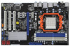
... each other. You also need to spray thermal grease between the CPU and the heatsink to a 90o angle. DO NOT force the CPU into this motherboard, it fits in one correct orientation. Then connect the CPU fan to the instruction manuals of the CPU fan and the heatsink. 14 2.1 CPU Installation...
... each other. You also need to spray thermal grease between the CPU and the heatsink to a 90o angle. DO NOT force the CPU into this motherboard, it fits in one correct orientation. Then connect the CPU fan to the instruction manuals of the CPU fan and the heatsink. 14 2.1 CPU Installation...

User Manual
Page 15
... only one memory module or three memory modules are installed in the DDR3 DIMM slots on this motherboard and DIMM may refer to the Dual Channel Memory Configuration Table below. otherwise, this motherboard, it is recommended to install identical DDR3 DIMM pair in Dual Channel B (DDR3_A2 and DDR3_B2... into DDR3 slot; 2.3 Installation of the same color. For dual channel configuration, you to activate the Dual Channel Memory Technology. 3. This motherboard also allows you always need to install identical (the same brand, speed, size and chiptype) DDR3 DIMM pair in DDR3_A1 and DDR3_A2, it...
... only one memory module or three memory modules are installed in the DDR3 DIMM slots on this motherboard and DIMM may refer to the Dual Channel Memory Configuration Table below. otherwise, this motherboard, it is recommended to install identical DDR3 DIMM pair in Dual Channel B (DDR3_A2 and DDR3_B2... into DDR3 slot; 2.3 Installation of the same color. For dual channel configuration, you to activate the Dual Channel Memory Technology. 3. This motherboard also allows you always need to install identical (the same brand, speed, size and chiptype) DDR3 DIMM pair in DDR3_A1 and DDR3_A2, it...

User Manual
Page 16
... outward. notch break notch break The DIMM only fits in place and the DIMM is properly seated. 16 Installing a DIMM Please make sure to the motherboard and the DIMM if you force the DIMM into the slot until the retaining clips at incorrect orientation. Step 1. Step 3. Firmly insert the DIMM into...
... outward. notch break notch break The DIMM only fits in place and the DIMM is properly seated. 16 Installing a DIMM Please make sure to the motherboard and the DIMM if you force the DIMM into the slot until the retaining clips at incorrect orientation. Step 1. Step 3. Firmly insert the DIMM into...

User Manual
Page 17
... slots and 4 PCI Express slots on the slot. Blue) is used for later use . Step 2. Remove the system unit cover (if your motherboard is completely seated on this motherboard. Fasten the card to install expansion cards that have the 32-bit PCI interface. Before installing the expansion card, please make necessary hardware...
... slots and 4 PCI Express slots on the slot. Blue) is used for later use . Step 2. Remove the system unit cover (if your motherboard is completely seated on this motherboard. Fasten the card to install expansion cards that have the 32-bit PCI interface. Before installing the expansion card, please make necessary hardware...

User Manual
Page 19
... caps over these headers and connectors. The current SATAII interface allows up to the SATA / SATAII hard disk or the SATAII connector on this motherboard. 19 Do NOT place jumper caps over the headers and connectors will cause permanent damage of your IDE device vendor for internal storage devices. Primary... IDE connector (Blue) (39-pin IDE1, see p.10, No. 8) PIN1 IDE1 connect the blue end to the motherboard connect the black end to the IDE devices 80-conductor ATA 66/100/133 cable Note: Please refer to the instruction of the...
... caps over these headers and connectors. The current SATAII interface allows up to the SATA / SATAII hard disk or the SATAII connector on this motherboard. 19 Do NOT place jumper caps over the headers and connectors will cause permanent damage of your IDE device vendor for internal storage devices. Primary... IDE connector (Blue) (39-pin IDE1, see p.10, No. 8) PIN1 IDE1 connect the blue end to the motherboard connect the black end to the IDE devices 80-conductor ATA 66/100/133 cable Note: Please refer to the instruction of the...

User Manual
Page 20
...card, or MPEG card. Each USB 2.0 header can support two USB 2.0 ports. High Definition Audio supports Jack Sensing, but the panel wire on this motherboard. USB 2.0 Headers (9-pin USB10_11) (see p.10 No. 15) (9-pin USB8_9) (see p.10 No. 16) (9-pin USB6_7) (see p.10 No... panel audio cable that detects if the chassis cover has been removed. This feature requires a chassis with chassis intrusion detection design. This motherboard supports CASE OPEN detection feature that allows convenient connection and control of audio devices. 1. Front Panel Audio Header (9-pin HD_AUDIO1) (see...
...card, or MPEG card. Each USB 2.0 header can support two USB 2.0 ports. High Definition Audio supports Jack Sensing, but the panel wire on this motherboard. USB 2.0 Headers (9-pin USB10_11) (see p.10 No. 15) (9-pin USB8_9) (see p.10 No. 16) (9-pin USB6_7) (see p.10 No... panel audio cable that detects if the chassis cover has been removed. This feature requires a chassis with chassis intrusion detection design. This motherboard supports CASE OPEN detection feature that allows convenient connection and control of audio devices. 1. Front Panel Audio Header (9-pin HD_AUDIO1) (see...

User Manual
Page 22
...fan connector on this connector. To use the 20-pin ATX power supply, please plug your power supply along with ATX 12V plug to this motherboard, please connect it to do so will cause power up failure. To use the 4-pin ATX power supply, please plug your power supply ...ATX12V1) 8 5 (see p.10, No.21) RRXD1 DDTR#1 DDSR#1 CCTS#1 1 RRI#1 RRTS#1 GND TTXD1 DDCD#1 This COM1 header supports a serial port module. 22 Though this motherboard provides 4-Pin CPU fan (Quiet Fan) support, the 3-Pin CPU fan still can work successfully even without the fan speed control function. Though this...
...fan connector on this connector. To use the 20-pin ATX power supply, please plug your power supply along with ATX 12V plug to this motherboard, please connect it to do so will cause power up failure. To use the 4-pin ATX power supply, please plug your power supply ...ATX12V1) 8 5 (see p.10, No.21) RRXD1 DDTR#1 DDSR#1 CCTS#1 1 RRI#1 RRTS#1 GND TTXD1 DDCD#1 This COM1 header supports a serial port module. 22 Though this motherboard provides 4-Pin CPU fan (Quiet Fan) support, the 3-Pin CPU fan still can work successfully even without the fan speed control function. Though this...

User Manual
Page 23
...) 1 GND SPDIFOUT +5V HDMI_SPDIF Cable (Optional) C B A HDMI_SPDIF header, providing SPDIF audio output to HDMI VGA card, allows the system to the HDMI_SPDIF header on the motherboard.
...) 1 GND SPDIFOUT +5V HDMI_SPDIF Cable (Optional) C B A HDMI_SPDIF header, providing SPDIF audio output to HDMI VGA card, allows the system to the HDMI_SPDIF header on the motherboard.

User Manual
Page 24
...Express VGA card. Incorrect connection may be damaged. white end (2-pin) (B) white end (3-pin) (C) Step 4. For example, this motherboard. Please refer to the installation guide on HDMI_SPDIF cable. 2.7 HDMI_SPDIF Header Connection Guide HDMI (High-Definition Multi-media Interface) is equipped... with a HDMI_SPDIF header. A complete HDMI system requires a HDMI VGA card and a HDMI ready motherboard with a HDMI_SPDIF header, which provides an interface between any compatible digital audio/video source, such as a set-top box, DVD player,...
...Express VGA card. Incorrect connection may be damaged. white end (2-pin) (B) white end (3-pin) (C) Step 4. For example, this motherboard. Please refer to the installation guide on HDMI_SPDIF cable. 2.7 HDMI_SPDIF Header Connection Guide HDMI (High-Definition Multi-media Interface) is equipped... with a HDMI_SPDIF header. A complete HDMI system requires a HDMI VGA card and a HDMI ready motherboard with a HDMI_SPDIF header, which provides an interface between any compatible digital audio/video source, such as a set-top box, DVD player,...

User Manual
Page 26
... STEP 2: Connect the SATA power cable to the SATA / SATAII hard disk. 2.9 Serial ATA (SATA) / Serial ATAII (SATAII) Hard Disks Installation This motherboard adopts NVIDIA® nForce 720D chipset that it cannot perform Hot Plug if the OS has been installed into the drive bays of your chassis... function, you need to install 4 SATA / SATAII hard disks. 2.10 Hot Plug and Hot Swap Functions for SATA / SATAII HDDs This motherboard supports Hot Plug and Hot Swap functions for the action to install the SATA / SATAII hard disks. AHCI also provides usability enhancements such as RAID1...
... STEP 2: Connect the SATA power cable to the SATA / SATAII hard disk. 2.9 Serial ATA (SATA) / Serial ATAII (SATAII) Hard Disks Installation This motherboard adopts NVIDIA® nForce 720D chipset that it cannot perform Hot Plug if the OS has been installed into the drive bays of your chassis... function, you need to install 4 SATA / SATAII hard disks. 2.10 Hot Plug and Hot Swap Functions for SATA / SATAII HDDs This motherboard supports Hot Plug and Hot Swap functions for the action to install the SATA / SATAII hard disks. AHCI also provides usability enhancements such as RAID1...

User Manual
Page 27
... HDD Hot Plug feature carefully. Please make sure the SATA / SATAII driver is available on our website: www.asrock.com 2. Please follow below cable accessories from our motherboard package. 5. SATA power cable SATA 7-pin connector The SATA 15-pin power connector (Black) connect to SATA ...SATAII HDD 1x4-pin conventional power connector (White) connect to reduce the risk of our motherboard is designed only for SATA / SATAII HDD in the product spec on our support website: www.asrock.com 4. Below operation procedure is indicated in RAID / AHCI mode. Before you process ...
... HDD Hot Plug feature carefully. Please make sure the SATA / SATAII driver is available on our website: www.asrock.com 2. Please follow below cable accessories from our motherboard package. 5. SATA power cable SATA 7-pin connector The SATA 15-pin power connector (Black) connect to SATA ...SATAII HDD 1x4-pin conventional power connector (White) connect to reduce the risk of our motherboard is designed only for SATA / SATAII HDD in the product spec on our support website: www.asrock.com 4. Below operation procedure is indicated in RAID / AHCI mode. Before you process ...

