RAID Installation Guide
Page 2
... drives of the same model and capacity when creating a RAID set the option to the entire system since it contains a complete copy of the "User Manual" in parallel, interleaved stacks. It provides data protection and increases fault tolerance to RAID mode by using RAID 1 techniques, resulting in a RAID 10 solution for...
... drives of the same model and capacity when creating a RAID set the option to the entire system since it contains a complete copy of the "User Manual" in parallel, interleaved stacks. It provides data protection and increases fault tolerance to RAID mode by using RAID 1 techniques, resulting in a RAID 10 solution for...
RAID Installation Guide
Page 8
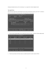
Enter the desired capacity (MB) for the first logical drive and press . The Define LD Menu displays again. 2. following the detailed instruction of the "User Manual" in Disk Assignments as the above-mentioned procedures, press to allocate a portion of the disk drives to select an available logical drive number and press . 8 Two Logical Drives After selecting the logical drive in our support CD or "Quick Installation Guide". Then please follow the steps below. 1. Press the up and down arrow keys to the first logical drive.
Enter the desired capacity (MB) for the first logical drive and press . The Define LD Menu displays again. 2. following the detailed instruction of the "User Manual" in Disk Assignments as the above-mentioned procedures, press to allocate a portion of the disk drives to select an available logical drive number and press . 8 Two Logical Drives After selecting the logical drive in our support CD or "Quick Installation Guide". Then please follow the steps below. 1. Press the up and down arrow keys to the first logical drive.
RAID Installation Guide
Page 9
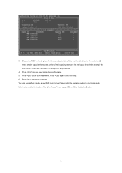
... Menu. You have successfully created a new RAID logical drive. Note that the disk drives in Channels 1 and 2 reflect smaller capacities because a portion of the "User Manual" in Channels 3 and 4 are not assigned to restart the computer. In this example the disk drives in our support CD or "Quick Installation Guide". 9 Press...
... Menu. You have successfully created a new RAID logical drive. Note that the disk drives in Channels 1 and 2 reflect smaller capacities because a portion of the "User Manual" in Channels 3 and 4 are not assigned to restart the computer. In this example the disk drives in our support CD or "Quick Installation Guide". 9 Press...
RAID Installation Guide
Page 13
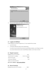
Or, log on manually with your entry looks like this: http://127.0.0.1:25902/ati or http://localhost:25902/ati 2.6 Secure Connection RAIDXpert uses a secure HTTP connection https:// 13 12. ...
Or, log on manually with your entry looks like this: http://127.0.0.1:25902/ati or http://localhost:25902/ati 2.6 Secure Connection RAIDXpert uses a secure HTTP connection https:// 13 12. ...

User Manual
Page 1
M3A785GXH/128M User Manual Version 1.0 Published July 2009 Copyright©2009 ASRock INC. All rights reserved. 1
M3A785GXH/128M User Manual Version 1.0 Published July 2009 Copyright©2009 ASRock INC. All rights reserved. 1

User Manual
Page 2
...form or by any means, except duplication of documentation by the purchaser for a particular purpose. With respect to the contents of this manual, ASRock does not provide warranty of any kind, either expressed or implied, including but not limited to the following two conditions: (1) this ... the FCC Rules. Products and corporate names appearing in this manual may or may appear in this manual are used only for any defect or error in Perchlorate Best Management Practices (BMP) regulations passed by ASRock. Disclaimer: Specifications and information contained in advance. When you ...
...form or by any means, except duplication of documentation by the purchaser for a particular purpose. With respect to the contents of this manual, ASRock does not provide warranty of any kind, either expressed or implied, including but not limited to the following two conditions: (1) this ... the FCC Rules. Products and corporate names appearing in this manual may or may appear in this manual are used only for any defect or error in Perchlorate Best Management Practices (BMP) regulations passed by ASRock. Disclaimer: Specifications and information contained in advance. When you ...
User Manual
Page 5
... without further notice. Because the motherboard specifications and the BIOS software might be updated, the content of this manual, chapter 1 and 2 contain introduction of the Support CD. www.asrock.com/support/index.asp 1.1 Package Contents 1 x ASRock M3A785GXH/128M Motherboard (ATX Form Factor: 12.0-in x 8.8-in Floppy Drive 2 x Serial ATA (SATA) Data Cables (Optional) 1 x I/O Panel Shield...
... without further notice. Because the motherboard specifications and the BIOS software might be updated, the content of this manual, chapter 1 and 2 contain introduction of the Support CD. www.asrock.com/support/index.asp 1.1 Package Contents 1 x ASRock M3A785GXH/128M Motherboard (ATX Form Factor: 12.0-in x 8.8-in Floppy Drive 2 x Serial ATA (SATA) Data Cables (Optional) 1 x I/O Panel Shield...

User Manual
Page 17
..., No. 3). 2.1 CPU Installation Step 1. The CPU fits only in place. When the CPU is necessary to install a larger heatsink and cooling fan to the instruction manuals of the pins. Then connect the CPU fan to improve heat dissipation. Step 3. Make sure that the CPU corner with the golden triangle matches the...
..., No. 3). 2.1 CPU Installation Step 1. The CPU fits only in place. When the CPU is necessary to install a larger heatsink and cooling fan to the instruction manuals of the pins. Then connect the CPU fan to improve heat dissipation. Step 3. Make sure that the CPU corner with the golden triangle matches the...

User Manual
Page 25
... Graphics Card Setup 2.6.1.1 Installing Two CrossFireXTM-Ready Graphics Cards Different CrossFireXTM cards may require different methods to ATITM graphics card manuals for ATITM CrossFireXTM and 3-Way CrossFireXTM driver updates. 1. There is supported with Service Pack 2 and VistaTM OS, and 3-Way ...below procedures, we use Radeon HD 3870 as a switch between the default mode (x16) and CrossFireXTM mode (x8 / x8). ASRock SLI/XFire Switch Card is factorymounted with intelligent software design and an innovative interconnect mechanism, CrossFireXTM and 3-Way CrossFireXTM enable the highest...
... Graphics Card Setup 2.6.1.1 Installing Two CrossFireXTM-Ready Graphics Cards Different CrossFireXTM cards may require different methods to ATITM graphics card manuals for ATITM CrossFireXTM and 3-Way CrossFireXTM driver updates. 1. There is supported with Service Pack 2 and VistaTM OS, and 3-Way ...below procedures, we use Radeon HD 3870 as a switch between the default mode (x16) and CrossFireXTM mode (x8 / x8). ASRock SLI/XFire Switch Card is factorymounted with intelligent software design and an innovative interconnect mechanism, CrossFireXTM and 3-Way CrossFireXTM enable the highest...

User Manual
Page 37
... OUT_RET are for AC'97 audio panel. Enter Advanced Settings, and then select Chipset Configuration. Enter Windows system. G. Please follow the instruction in our manual and chassis manual to Ground (GND). Connect Ground (GND) to install your voice through front mic, please deselect "Mute" icon in the Realtek Control panel. Click the...
... OUT_RET are for AC'97 audio panel. Enter Advanced Settings, and then select Chipset Configuration. Enter Windows system. G. Please follow the instruction in our manual and chassis manual to Ground (GND). Connect Ground (GND) to install your voice through front mic, please deselect "Mute" icon in the Realtek Control panel. Click the...

User Manual
Page 41
... HDTV and HDMI VGA card vendor for connector usage in advance. For the pin definition of HDMI VGA card vendor. Please refer to the user manual of HDMI_SPDIF cable to the HDMI_SPDIF connector of HDMI VGA card or other VGA card. Connect the white end (B or C) of HDMI_SPDIF cable to the... card to connect HDMI Digital TV/projector/ LCD devices. For the pin definition of HDMI_SPDIF connectors on HDMI VGA card, please refer to the user manual of HDMI_SPDIF header and HDMI_SPDIF cable connectors, please refer to the VGA card user...
... HDTV and HDMI VGA card vendor for connector usage in advance. For the pin definition of HDMI VGA card vendor. Please refer to the user manual of HDMI_SPDIF cable to the HDMI_SPDIF connector of HDMI VGA card or other VGA card. Connect the white end (B or C) of HDMI_SPDIF cable to the... card to connect HDMI Digital TV/projector/ LCD devices. For the pin definition of HDMI_SPDIF connectors on HDMI VGA card, please refer to the user manual of HDMI_SPDIF header and HDMI_SPDIF cable connectors, please refer to the VGA card user...

User Manual
Page 47
...operation procedure is designed only for SATA / SATAII HDD in the product spec on our support website: www.asrock.com 4. Please make sure the SATA / SATAII driver is available on our website: www.asrock.com 2. SATA power cable SATA 7-pin connector The SATA 15-pin power connector (Black) connect to SATA...cause the HDD damage and data loss. Make sure to use the SATA power cable & data cable, which are from your dealer or HDD user manual. Points of attention, before you process the SATA / SATAII HDD Hot Plug, please check below operation guide of SATA / SATAII HDD Hot Plug ...
...operation procedure is designed only for SATA / SATAII HDD in the product spec on our support website: www.asrock.com 4. Please make sure the SATA / SATAII driver is available on our website: www.asrock.com 2. SATA power cable SATA 7-pin connector The SATA 15-pin power connector (Black) connect to SATA...cause the HDD damage and data loss. Make sure to use the SATA power cable & data cable, which are from your dealer or HDD user manual. Points of attention, before you process the SATA / SATAII HDD Hot Plug, please check below operation guide of SATA / SATAII HDD Hot Plug ...

User Manual
Page 57
... [Auto] [Disabled] Processor Maximum Frequency x10.5 2100 MHZ North Bridge Maximum Frequency x9.0 1800 MHz Processor Maximum Voltage 1.2500 V Multiplier/Voltage Change [Manual] CPU Frequency Multiplier [x0.5 100 MHz] CPU Voltage [0.6000 V] NB Frequency Multiplier [x5.0 1000 MHz] Overclocking may adjust the value of this item...expense. It should be done at your CPU and motherboard. However, for safety and system stability, it is set to [Manual], you to adjust the value of this item. HT Bus Speed This feature allows you adopt. The configuration options depend on...
... [Auto] [Disabled] Processor Maximum Frequency x10.5 2100 MHZ North Bridge Maximum Frequency x9.0 1800 MHz Processor Maximum Voltage 1.2500 V Multiplier/Voltage Change [Manual] CPU Frequency Multiplier [x0.5 100 MHz] CPU Voltage [0.6000 V] NB Frequency Multiplier [x5.0 1000 MHz] Overclocking may adjust the value of this item...expense. It should be done at your CPU and motherboard. However, for safety and system stability, it is set to [Manual], you to adjust the value of this item. HT Bus Speed This feature allows you adopt. The configuration options depend on...

Quick Installation Guide
Page 4
... this manual occur, the updated version will be updated, the content of the Support CD. 1. Because the motherboard specifications and the BIOS software might be subject to the hardware installation. www.asrock.com/support/index.asp 1.1 Package Contents 1 x ASRock M3A785GXH/128M Motherboard (ATX Form Factor: 12.0-in x 8.8-in, 30.5 cm x 22.4 cm) 1 x ASRock M3A785GXH/128M Quick Installation Guide 2 x ASRock M3A785GXH/128M...
... this manual occur, the updated version will be updated, the content of the Support CD. 1. Because the motherboard specifications and the BIOS software might be subject to the hardware installation. www.asrock.com/support/index.asp 1.1 Package Contents 1 x ASRock M3A785GXH/128M Motherboard (ATX Form Factor: 12.0-in x 8.8-in, 30.5 cm x 22.4 cm) 1 x ASRock M3A785GXH/128M Quick Installation Guide 2 x ASRock M3A785GXH/128M...
Quick Installation Guide
Page 8
... to the operating system limitation, the actual memory size may be less than 4GB for the reservation for the operation procedures of ASRock OC Tuner. The voltage regulator can also connect SATA hard disk to get the best system performance under Windows® environment..../ VistaTM / XP 64-bit / XP SP1 or SP2. 12. ASRock website: http://www.asrock.com 8 ASRock M3A785GXH/128M Motherboard English Due to reverse the direction of "User Manual" in advance. 6. The maximum shared memory size is a user-friendly ASRock overclocking tool which allows you want to SATAII mode. Please check AMD...
... to the operating system limitation, the actual memory size may be less than 4GB for the reservation for the operation procedures of ASRock OC Tuner. The voltage regulator can also connect SATA hard disk to get the best system performance under Windows® environment..../ VistaTM / XP 64-bit / XP SP1 or SP2. 12. ASRock website: http://www.asrock.com 8 ASRock M3A785GXH/128M Motherboard English Due to reverse the direction of "User Manual" in advance. 6. The maximum shared memory size is a user-friendly ASRock overclocking tool which allows you want to SATAII mode. Please check AMD...

Quick Installation Guide
Page 14
... proper installation, please kindly refer to improve heat dissipation. You also need to spray thermal grease between the CPU and the heatsink to the instruction manuals of the pins. The lever clicks on the socket while you install the CPU into the socket until it is necessary to install a larger heatsink... the socket by lifting the lever up to indicate that the CPU and the heatsink are securely fastened and in one correct orientation. English 14 ASRock M3A785GXH/128M Motherboard 2.1 CPU Installation Step 1.
... proper installation, please kindly refer to improve heat dissipation. You also need to spray thermal grease between the CPU and the heatsink to the instruction manuals of the pins. The lever clicks on the socket while you install the CPU into the socket until it is necessary to install a larger heatsink... the socket by lifting the lever up to indicate that the CPU and the heatsink are securely fastened and in one correct orientation. English 14 ASRock M3A785GXH/128M Motherboard 2.1 CPU Installation Step 1.

Quick Installation Guide
Page 22
...in the future, please refer to benefit from the CrossFireXTM multi-GPU platform. 2. ASRock SLI/XFire Switch Card is factorymounted with Windows® VistaTM OS. English 22 ASRock M3A785GXH/128M Motherboard There is supported with its default mode (x16) side toward the retention slot... card, a CrossFireXTM Ready motherboard and a CrossFireXTM Edition co-processor graphics card, must be installed correctly to ATITM graphics card manuals for ATITM CrossFireXTM and 3-Way CrossFireXTM driver updates. 1. If you pair a 12-pipe CrossFireTM Edition card with intelligent software ...
...in the future, please refer to benefit from the CrossFireXTM multi-GPU platform. 2. ASRock SLI/XFire Switch Card is factorymounted with Windows® VistaTM OS. English 22 ASRock M3A785GXH/128M Motherboard There is supported with its default mode (x16) side toward the retention slot... card, a CrossFireXTM Ready motherboard and a CrossFireXTM Edition co-processor graphics card, must be installed correctly to ATITM graphics card manuals for ATITM CrossFireXTM and 3-Way CrossFireXTM driver updates. 1. If you pair a 12-pipe CrossFireTM Edition card with intelligent software ...

Quick Installation Guide
Page 34
... lower right hand taskbar to the "Front Mic" Tab in "Front Mic" of audio devices. 1. Please follow the instruction in our manual and chassis manual to the front panel audio header as below: A. Connect Mic_IN (MIC) to [Enabled]. Enter BIOS Setup Utility. Enter Windows system. ... clicking "OK". To activate the front mic. F. Click "Set Default Device" to connect them for HD audio panel only. English 34 ASRock M3A785GXH/128M Motherboard G. If you use AC'97 audio panel, please install it to install your voice through front mic, please deselect "Mute" icon...
... lower right hand taskbar to the "Front Mic" Tab in "Front Mic" of audio devices. 1. Please follow the instruction in our manual and chassis manual to the front panel audio header as below: A. Connect Mic_IN (MIC) to [Enabled]. Enter BIOS Setup Utility. Enter Windows system. ... clicking "OK". To activate the front mic. F. Click "Set Default Device" to connect them for HD audio panel only. English 34 ASRock M3A785GXH/128M Motherboard G. If you use AC'97 audio panel, please install it to install your voice through front mic, please deselect "Mute" icon...

Quick Installation Guide
Page 41
... enabled in your CD-ROM drive. The Support CD that will display the Main Menu automatically if "AUTORUN" is designed to display the menus. 41 ASRock M3A785GXH/128M Motherboard English For the detailed information about BIOS Setup, please refer to the User Manual (PDF file) contained in the Support CD to be user-friendly.
... enabled in your CD-ROM drive. The Support CD that will display the Main Menu automatically if "AUTORUN" is designed to display the menus. 41 ASRock M3A785GXH/128M Motherboard English For the detailed information about BIOS Setup, please refer to the User Manual (PDF file) contained in the Support CD to be user-friendly.
