User Manual
Page 5
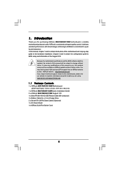
... any modifications of the Support CD. www.asrock.com/support/index.asp 1.1 Package Contents 1 x ASRock M3A785GXH/128M Motherboard (ATX Form Factor: 12.0-in x 8.8-in, 30.5 cm x 22.4 cm) 1 x ASRock M3A785GXH/128M Quick Installation Guide 2 x ASRock M3A785GXH/128M Support CD 1 x Ultra ATA 66/100/133 IDE Ribbon Cable (80-conductor) 1 x Ribbon Cable for purchasing ASRock M3A785GXH/128M motherboard, a reliable motherboard produced under ASRock's consistently stringent quality control. It delivers...
... any modifications of the Support CD. www.asrock.com/support/index.asp 1.1 Package Contents 1 x ASRock M3A785GXH/128M Motherboard (ATX Form Factor: 12.0-in x 8.8-in, 30.5 cm x 22.4 cm) 1 x ASRock M3A785GXH/128M Quick Installation Guide 2 x ASRock M3A785GXH/128M Support CD 1 x Ultra ATA 66/100/133 IDE Ribbon Cable (80-conductor) 1 x Ribbon Cable for purchasing ASRock M3A785GXH/128M motherboard, a reliable motherboard produced under ASRock's consistently stringent quality control. It delivers...

User Manual
Page 14
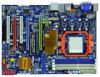
... Red) 38 PCI Express 2.0 x16 Slot (PCIE3; White) 30 Chassis Fan Connector (CHA_FAN1) 9 ATX Power Connector (ATXPWR1) 31 Floppy Connector (FLOPPY1) 10 North Bridge Fan Connector (NB_FAN1) 32 Serial ...64 bit, 240-pin module) DDR3_A1 (64 bit, 240-FpinSBmo8d0ul0e) Dual Channel FSB2.6GHz 140W CPU AM3 1.7 Motherboard Layout USB 2.0 T: USB4 B: USB5 1 23 4 1 PS2_USB_PW1 5 6 22.4cm (8.8-in) PS2 Keyboard...Top: LINE IN Center: Bottom: 785G NB_FAN1 41 PWR_FAN1 Chipset PCIE1 LAN PHY 40 M3A785GXH/128M 39 PCIE2 IDE1 CrossFireX Hybrid CrossFire 38 37 36 35 34 Super I/O AUDIO CODEC...
... Red) 38 PCI Express 2.0 x16 Slot (PCIE3; White) 30 Chassis Fan Connector (CHA_FAN1) 9 ATX Power Connector (ATXPWR1) 31 Floppy Connector (FLOPPY1) 10 North Bridge Fan Connector (NB_FAN1) 32 Serial ...64 bit, 240-pin module) DDR3_A1 (64 bit, 240-FpinSBmo8d0ul0e) Dual Channel FSB2.6GHz 140W CPU AM3 1.7 Motherboard Layout USB 2.0 T: USB4 B: USB5 1 23 4 1 PS2_USB_PW1 5 6 22.4cm (8.8-in) PS2 Keyboard...Top: LINE IN Center: Bottom: 785G NB_FAN1 41 PWR_FAN1 Chipset PCIE1 LAN PHY 40 M3A785GXH/128M 39 PCIE2 IDE1 CrossFireX Hybrid CrossFire 38 37 36 35 34 Super I/O AUDIO CODEC...

User Manual
Page 16
... ensure that comes with the component. 5. To avoid damaging the motherboard components due to static electricity, NEVER place your chassis to ensure that the motherboard fits into the screw holes to secure the motherboard to the motherboard, peripherals, and/or components. 1. Also remember to do not ...touch the ICs. 4. Installation This is an ATX form factor (12.0-in x 8.8-in the bag...
... ensure that comes with the component. 5. To avoid damaging the motherboard components due to static electricity, NEVER place your chassis to ensure that the motherboard fits into the screw holes to secure the motherboard to the motherboard, peripherals, and/or components. 1. Also remember to do not ...touch the ICs. 4. Installation This is an ATX form factor (12.0-in x 8.8-in the bag...

User Manual
Page 27
... cable to the DVI to connect two Radeon graphics cards. (CrossFireTM Bridge is provided with the graphics card you purchase, not bundled with this motherboard. Please refer to section "Expansion Slots". If there are two gold fingers on the top of Radeon graphics cards. For the proper installation procedures..., please refer to your graphics card vendor for details.) CrossFireTM Bridge Step 8. Connect a 4-pin ATX power cable to PCIE3 slot. Install one Radeon graphics card to SLI/XFIRE power connector. 27
... cable to the DVI to connect two Radeon graphics cards. (CrossFireTM Bridge is provided with the graphics card you purchase, not bundled with this motherboard. Please refer to section "Expansion Slots". If there are two gold fingers on the top of Radeon graphics cards. For the proper installation procedures..., please refer to your graphics card vendor for details.) CrossFireTM Bridge Step 8. Connect a 4-pin ATX power cable to PCIE3 slot. Install one Radeon graphics card to SLI/XFIRE power connector. 27

User Manual
Page 38
... 24 it to Pin 1-3. Pin 1-3 Connected 3-Pin Fan Installation ATX Power Connector (24-pin ATXPWR1) (see p.14 No. 1) 20-Pin ATX Power Supply Installation 1 13 4 8 1 5 Please connect an ATX 12V power supply to this motherboard, please connect it can work if you plan to connect the... 3-Pin CPU fan to this connector. 1 13 Though this header. ATX 12V Power Connector (8-pin ATX12V1) (see...
... 24 it to Pin 1-3. Pin 1-3 Connected 3-Pin Fan Installation ATX Power Connector (24-pin ATXPWR1) (see p.14 No. 1) 20-Pin ATX Power Supply Installation 1 13 4 8 1 5 Please connect an ATX 12V power supply to this motherboard, please connect it can work if you plan to connect the... 3-Pin CPU fan to this connector. 1 13 Though this header. ATX 12V Power Connector (8-pin ATX12V1) (see...

User Manual
Page 39
... Please connect the HDMI_SPDIF connector of HDMI VGA card to connect HDMI Digital TV/ projector/LCD devices. Though this motherboard provides 8-pin ATX 12V power connector, it with Pin 1 and Pin 5. 4 8 4-Pin ATX 12V Power Supply Installation 1 5 SLI/XFIRE Power Connector (4-pin SLI/XFIRE_PWR1) (see p.14 No. 35)...on the I/O panel, there is not necessary to use the 4-pin ATX power supply, please plug your power supply along with a hard disk power connecor when two graphics cards are plugged to this motherboard at the same time. HDMI_SPDIF header, providing SPDIF audio output to HDMI ...
... Please connect the HDMI_SPDIF connector of HDMI VGA card to connect HDMI Digital TV/ projector/LCD devices. Though this motherboard provides 8-pin ATX 12V power connector, it with Pin 1 and Pin 5. 4 8 4-Pin ATX 12V Power Supply Installation 1 5 SLI/XFIRE Power Connector (4-pin SLI/XFIRE_PWR1) (see p.14 No. 35)...on the I/O panel, there is not necessary to use the 4-pin ATX power supply, please plug your power supply along with a hard disk power connecor when two graphics cards are plugged to this motherboard at the same time. HDMI_SPDIF header, providing SPDIF audio output to HDMI ...

Quick Installation Guide
Page 2
... (SPEAKER 1, Purple) 41 Power Fan Connector (PWR_FAN1) 22 Fifth SATAII Connector (SATAII_5, Red) 42 eSATAII Connector (eSATAII_TOP) 2 ASRock M3A785GXH/128M Motherboard Orange) 18 Secondary SATAII Connector (SATAII_2, Red) 37 PCI Slots (PCI1- 2) 19 Fourth SATAII Connector (SATAII_4, Red) 38...USB6_7, Blue) 8 2 x 240-pin DDR3 DIMM Slots 29 USB 2.0 Header (USB8_9, Blue) (Dual Channel B: DDR3_A2, DDR3_B2; Motherboard Layout English 1 ATX 12V Power Connector (ATX12V1) 23 Sixth SATAII Connector 2 PS2_USB_PW1 Jumper (SATAII_6, Orange) 3 CPU Fan Connector (CPU_FAN1) 24 Infrared Module...
... (SPEAKER 1, Purple) 41 Power Fan Connector (PWR_FAN1) 22 Fifth SATAII Connector (SATAII_5, Red) 42 eSATAII Connector (eSATAII_TOP) 2 ASRock M3A785GXH/128M Motherboard Orange) 18 Secondary SATAII Connector (SATAII_2, Red) 37 PCI Slots (PCI1- 2) 19 Fourth SATAII Connector (SATAII_4, Red) 38...USB6_7, Blue) 8 2 x 240-pin DDR3 DIMM Slots 29 USB 2.0 Header (USB8_9, Blue) (Dual Channel B: DDR3_A2, DDR3_B2; Motherboard Layout English 1 ATX 12V Power Connector (ATX12V1) 23 Sixth SATAII Connector 2 PS2_USB_PW1 Jumper (SATAII_6, Orange) 3 CPU Fan Connector (CPU_FAN1) 24 Infrared Module...

Quick Installation Guide
Page 4
... of this manual, chapter 1 and 2 contain introduction of the Support CD. www.asrock.com/support/index.asp 1.1 Package Contents 1 x ASRock M3A785GXH/128M Motherboard (ATX Form Factor: 12.0-in x 8.8-in Floppy Drive 2 x Serial ATA (SATA) Data Cables (Optional) 1 x I/O Panel Shield 1 x ASRock SLI/XFire Switch Card 4 ASRock M3A785GXH/128M Motherboard English Chapter 3 and 4 contain the configuration guide to BIOS setup and information of...
... of this manual, chapter 1 and 2 contain introduction of the Support CD. www.asrock.com/support/index.asp 1.1 Package Contents 1 x ASRock M3A785GXH/128M Motherboard (ATX Form Factor: 12.0-in x 8.8-in Floppy Drive 2 x Serial ATA (SATA) Data Cables (Optional) 1 x I/O Panel Shield 1 x ASRock SLI/XFire Switch Card 4 ASRock M3A785GXH/128M Motherboard English Chapter 3 and 4 contain the configuration guide to BIOS setup and information of...

Quick Installation Guide
Page 5
...Max. capacity of system memory: 16GB (see CAUTION 7) - 7.1 CH Windows® VistaTM Premium Level HD Audio (ALC888 Audio Codec) English 5 ASRock M3A785GXH/128M Motherboard Supports Full HD 1080p Blu-ray (BD) / HD-DVD playback (see CAUTION 4) - 3 x PCI Express 2.0 x16 slots (green @ x16...function - All Solid Capacitor design (100% Japan-made high-quality Conductive Polymer Capacitors) - DX10.1 class iGPU, Shader Model 4.1 - Max. ATX Form Factor: 12.0-in x 8.8-in 128MB DDR3 1333(OC)/1200MHz SidePort Memory - Dual Channel DDR3 Memory Technology (see CAUTION 6) - FSB ...
...Max. capacity of system memory: 16GB (see CAUTION 7) - 7.1 CH Windows® VistaTM Premium Level HD Audio (ALC888 Audio Codec) English 5 ASRock M3A785GXH/128M Motherboard Supports Full HD 1080p Blu-ray (BD) / HD-DVD playback (see CAUTION 4) - 3 x PCI Express 2.0 x16 slots (green @ x16...function - All Solid Capacitor design (100% Japan-made high-quality Conductive Polymer Capacitors) - DX10.1 class iGPU, Shader Model 4.1 - Max. ATX Form Factor: 12.0-in x 8.8-in 128MB DDR3 1333(OC)/1200MHz SidePort Memory - Dual Channel DDR3 Memory Technology (see CAUTION 6) - FSB ...

Quick Installation Guide
Page 6
... - 1 x COM port header - 1 x IEEE 1394 header - 1 x HDMI_SPDIF header - Realtek RTL8111DL - CPU/Chassis/NB/Power FAN connector - 24 pin ATX power connector - 8 pin 12V power connector - Supports jumperfree - CD in /Front Speaker/Microphone (see CAUTION 8) Connector - 6 x Serial ATAII 3.0Gb/s connectors...adjustment - HD Audio Jack: Side Speaker/Rear Speaker/Central/Bass/ Line in header - AMI Legal BIOS - Supports Smart BIOS 6 ASRock M3A785GXH/128M Motherboard PCIE x1 Gigabit LAN 10/100/1000 Mb/s - Front panel audio connector - 3 x USB 2.0 headers (support 6 USB 2.0 ...
... - 1 x COM port header - 1 x IEEE 1394 header - 1 x HDMI_SPDIF header - Realtek RTL8111DL - CPU/Chassis/NB/Power FAN connector - 24 pin ATX power connector - 8 pin 12V power connector - Supports jumperfree - CD in /Front Speaker/Microphone (see CAUTION 8) Connector - 6 x Serial ATAII 3.0Gb/s connectors...adjustment - HD Audio Jack: Side Speaker/Rear Speaker/Central/Bass/ Line in header - AMI Legal BIOS - Supports Smart BIOS 6 ASRock M3A785GXH/128M Motherboard PCIE x1 Gigabit LAN 10/100/1000 Mb/s - Front panel audio connector - 3 x USB 2.0 headers (support 6 USB 2.0 ...

Quick Installation Guide
Page 13
... ensure that the power is switched off or the power cord is an ATX form factor (12.0-in x 8.8-in the bag that the motherboard fits into the screw holes to secure the motherboard to the chassis, please do not over-tighten the screws! Unplug the .... 5. Hold components by the edges and do so may damage the motherboard. 13 ASRock M3A785GXH/128M Motherboard English 2. Before you handle components. 3. To avoid damaging the motherboard components due to static electricity, NEVER place your chassis to the motherboard, peripherals, and/or components. 1. When placing screws into it on...
... ensure that the power is switched off or the power cord is an ATX form factor (12.0-in x 8.8-in the bag that the motherboard fits into the screw holes to secure the motherboard to the chassis, please do not over-tighten the screws! Unplug the .... 5. Hold components by the edges and do so may damage the motherboard. 13 ASRock M3A785GXH/128M Motherboard English 2. Before you handle components. 3. To avoid damaging the motherboard components due to static electricity, NEVER place your chassis to the motherboard, peripherals, and/or components. 1. When placing screws into it on...

Quick Installation Guide
Page 24
Please refer to SLI/XFIRE power connector. 24 ASRock M3A785GXH/128M Motherboard English Connect a 4-pin ATX power cable to your graphics card vendor for details.) CrossFireTM Bridge Step 8. Step 7. If there are two gold fingers on each Radeon graphics card,... cable to the DVI to connect two Radeon graphics cards. (CrossFireTM Bridge is provided with the graphics card you purchase, not bundled with this motherboard. Connect two Radeon graphics cards by installing CrossFireTM Bridge on CrossFireTM Bridge Interconnects on PCIE2 slot. (You may use two CrossFireTM Bridge to D-Sub...
Please refer to SLI/XFIRE power connector. 24 ASRock M3A785GXH/128M Motherboard English Connect a 4-pin ATX power cable to your graphics card vendor for details.) CrossFireTM Bridge Step 8. Step 7. If there are two gold fingers on each Radeon graphics card,... cable to the DVI to connect two Radeon graphics cards. (CrossFireTM Bridge is provided with the graphics card you purchase, not bundled with this motherboard. Connect two Radeon graphics cards by installing CrossFireTM Bridge on CrossFireTM Bridge Interconnects on PCIE2 slot. (You may use two CrossFireTM Bridge to D-Sub...

Quick Installation Guide
Page 26
English 26 ASRock M3A785GXH/128M Motherboard CrossFireTM Bridge Step 6. Connect the DVI monitor cable to the DVI connector on the Radeon graphics card on PCIE2 slot. (You may use the DVI to D-Sub adapter to convert the DVI connector to D-Sub interface, and then connect the D-Sub monitor cable to the DVI to SLI/XFIRE power connector. Connect a 4-pin ATX power cable to D-Sub adapter.) Step 7.
English 26 ASRock M3A785GXH/128M Motherboard CrossFireTM Bridge Step 6. Connect the DVI monitor cable to the DVI connector on the Radeon graphics card on PCIE2 slot. (You may use the DVI to D-Sub adapter to convert the DVI connector to D-Sub interface, and then connect the D-Sub monitor cable to the DVI to SLI/XFIRE power connector. Connect a 4-pin ATX power cable to D-Sub adapter.) Step 7.

Quick Installation Guide
Page 35
... header. If you plan to connect the 3-Pin CPU fan to the CPU fan connector on this motherboard, please connect it can work if you adopt a traditional 20-pin ATX power supply. English 35 ASRock M3A785GXH/128M Motherboard ATX 12V Power Connector (8-pin ATX12V1) (see p.2 No. 3) Please connect the CPU fan 4 cable...p.2 No. 21) Chassis, NB and Power Fan Connectors (3-pin CHA_FAN1) (see p.2 No. 30) (3-pin NB_FAN1) (see p.2 No. 9) 12 24 Please connect an ATX power supply to this connector. 1 13 Though this motherboard provides 24-pin ATX power connector, 12 24 it to Pin 1-3.
... header. If you plan to connect the 3-Pin CPU fan to the CPU fan connector on this motherboard, please connect it can work if you adopt a traditional 20-pin ATX power supply. English 35 ASRock M3A785GXH/128M Motherboard ATX 12V Power Connector (8-pin ATX12V1) (see p.2 No. 3) Please connect the CPU fan 4 cable...p.2 No. 21) Chassis, NB and Power Fan Connectors (3-pin CHA_FAN1) (see p.2 No. 30) (3-pin NB_FAN1) (see p.2 No. 9) 12 24 Please connect an ATX power supply to this connector. 1 13 Though this motherboard provides 24-pin ATX power connector, 12 24 it to Pin 1-3.

Quick Installation Guide
Page 36
... Header (3-pin HDMI_SPDIF1) (see p.2 No. 4) SLI/XFIRE_POWER1 It is one IEEE 1394 port. English 36 ASRock M3A785GXH/128M Motherboard This COM1 header supports a serial port module. Though this motherboard provides 8-pin ATX 12V power connector, it with Pin 1 and Pin 5. 4 8 4-Pin ATX 12V Power Supply Installation 1 5 SLI/XFIRE Power Connector (4-pin SLI/XFIRE_PWR1) (see p.2 No. 35) HDMI_SPDIF...
... Header (3-pin HDMI_SPDIF1) (see p.2 No. 4) SLI/XFIRE_POWER1 It is one IEEE 1394 port. English 36 ASRock M3A785GXH/128M Motherboard This COM1 header supports a serial port module. Though this motherboard provides 8-pin ATX 12V power connector, it with Pin 1 and Pin 5. 4 8 4-Pin ATX 12V Power Supply Installation 1 5 SLI/XFIRE Power Connector (4-pin SLI/XFIRE_PWR1) (see p.2 No. 35) HDMI_SPDIF...

