RAID Installation Guide
Page 2
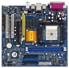
STEP 2: Connect the SATA power cable to install the SATA hard disks. You may install SATA hard disks on this motherboard for internal storage devices. This section will guide you to the SATA hard disk. STEP 1: Install the SATA hard disks into the drive bays of ...the SATA data cable to the motherboard's SATA connector. STEP 3: Connect one end of the SATA data cable to the SATA hard disk. 2 STEP 4: Connect the other end of your chassis. Guide...
STEP 2: Connect the SATA power cable to install the SATA hard disks. You may install SATA hard disks on this motherboard for internal storage devices. This section will guide you to the SATA hard disk. STEP 1: Install the SATA hard disks into the drive bays of ...the SATA data cable to the motherboard's SATA connector. STEP 3: Connect one end of the SATA data cable to the SATA hard disk. 2 STEP 4: Connect the other end of your chassis. Guide...
RAID Installation Guide
Page 4
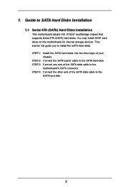
... Array of RAID, and the guide to read and write data in parallel, interleaved stacks. For optimal performance, please install identical drives of RAID This motherboard adopts VIA VT8237 south bridge chipset that optimizes two identical hard disk drives to configure RAID 0, RAID 1, and JBOD settings. Guide to RAID Configurations 2.1 Introduction...
... Array of RAID, and the guide to read and write data in parallel, interleaved stacks. For optimal performance, please install identical drives of RAID This motherboard adopts VIA VT8237 south bridge chipset that optimizes two identical hard disk drives to configure RAID 0, RAID 1, and JBOD settings. Guide to RAID Configurations 2.1 Introduction...
User Manual
Page 3
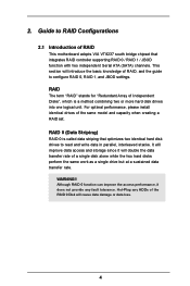
... 64-bit With RAID Functions ....... 20 2.10 Installing Windows 98 / ME / 2000 / XP / XP 64-bit Without RAID Functions 21 3 . Contents 1 . Introduction 5 1.1 Package Contents 5 1.2 Specifications 6 1.3 Motherboard Layout 8 1.4 ASRock I/O PlusTM 9 2 .
... 64-bit With RAID Functions ....... 20 2.10 Installing Windows 98 / ME / 2000 / XP / XP 64-bit Without RAID Functions 21 3 . Contents 1 . Introduction 5 1.1 Package Contents 5 1.2 Specifications 6 1.3 Motherboard Layout 8 1.4 ASRock I/O PlusTM 9 2 .

User Manual
Page 5
1. Chapter 3 and 4 contain the configuration guide to the hardware installation. ASRock website http://www.asrock.com 1.1 Package Contents 1 x ASRock K8Upgrade-VM800 Motherboard (Micro ATX Form Factor: 9.0-in x 9.6-in, 22.9 cm x 24.4 cm) 1 x ASRock K8Upgrade-VM800 Quick Installation Guide 1 x ASRock K8Upgrade-VM800 Support CD 1 x Ultra ATA 66/100/133 IDE Ribbon Cable (80-conductor) 1 x 3.5-in Floppy Drive Ribbon Cable 1 x Serial ATA (SATA) Data Cable...
1. Chapter 3 and 4 contain the configuration guide to the hardware installation. ASRock website http://www.asrock.com 1.1 Package Contents 1 x ASRock K8Upgrade-VM800 Motherboard (Micro ATX Form Factor: 9.0-in x 9.6-in, 22.9 cm x 24.4 cm) 1 x ASRock K8Upgrade-VM800 Quick Installation Guide 1 x ASRock K8Upgrade-VM800 Support CD 1 x Ultra ATA 66/100/133 IDE Ribbon Cable (80-conductor) 1 x 3.5-in Floppy Drive Ribbon Cable 1 x Serial ATA (SATA) Data Cable...
User Manual
Page 6
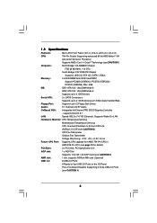
... 8.1 LAN: Speed: 802.3u (10/100 Ethernet), Supports Wake-On-LAN Hardware Monitor: CPU Temperature Sensing Motherboard Temperature Sensing CPU Overheat Shutdown to Protect CPU Life (ASRock U-COP)(see CAUTION 2) CPU Fan Tachometer Chassis Fan Tachometer Voltage Monitoring: +12V, +5V, +3.3V, Vcore... x PCI Slots, PCI Specification 2.2 AGP slot: 1 x AGP Slot Supports 1.5V, 8X / 4X AGP Card (see CAUTION 3) AMR slot: 1 slot, supports ASRock MR card (Optional) USB 2.0: 8 USB 2.0 Ports: 6 Ready-to-Use USB 2.0 Ports on the I/O Panel Plus 2 On-Board Headers Supporting 2 Extra USB 2.0 Ports...
... 8.1 LAN: Speed: 802.3u (10/100 Ethernet), Supports Wake-On-LAN Hardware Monitor: CPU Temperature Sensing Motherboard Temperature Sensing CPU Overheat Shutdown to Protect CPU Life (ASRock U-COP)(see CAUTION 2) CPU Fan Tachometer Chassis Fan Tachometer Voltage Monitoring: +12V, +5V, +3.3V, Vcore... x PCI Slots, PCI Specification 2.2 AGP slot: 1 x AGP Slot Supports 1.5V, 8X / 4X AGP Card (see CAUTION 3) AMR slot: 1 slot, supports ASRock MR card (Optional) USB 2.0: 8 USB 2.0 Ports: 6 Ready-to-Use USB 2.0 Ports on the I/O Panel Plus 2 On-Board Headers Supporting 2 Extra USB 2.0 Ports...
User Manual
Page 7
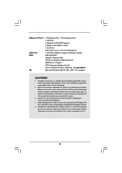
... OS: Microsoft® Windows® 98 SE / ME / 2000 / XP compliant CAUTION! 1. It may cause the instability of this motherboard offers stepless control, it is strongly recommended to enable AMD's Cool 'n' QuietTM technology under Microsoft® Windows® 98/ ME. 5. ...Frequencies other than the recommended CPU bus frequencies may cause permanent damage! 4. ASRock I/O PlusTM: 1 PS/2 Mouse Port, 1 PS/2 Keyboard Port 1 VGA Port 1 Parallel Port (ECP/EPP Support) 6 Ready-to-Use USB 2.0...
... OS: Microsoft® Windows® 98 SE / ME / 2000 / XP compliant CAUTION! 1. It may cause the instability of this motherboard offers stepless control, it is strongly recommended to enable AMD's Cool 'n' QuietTM technology under Microsoft® Windows® 98/ ME. 5. ...Frequencies other than the recommended CPU bus frequencies may cause permanent damage! 4. ASRock I/O PlusTM: 1 PS/2 Mouse Port, 1 PS/2 Keyboard Port 1 VGA Port 1 Parallel Port (ECP/EPP Support) 6 Ready-to-Use USB 2.0...

User Manual
Page 8
J8 Jumpers 8 1.3 Motherboard Layout 123 45 22.9cm (9.0-in) PS2 Mouse PS2_USB_PW1 1 CPU_FAN1 ATX12V1 67 89 J15 1 IR1 1 PS2 Keyboard 4Mb BIOS Super I/O PARALLEL PORT ATXPWR1 FSB800 DDR2 (... 1 JR1 JL1 AUX1 LAN PHY USB45 USB2.0 1 1 J7 J8 1 1 J5 J6 1 1 J3 J4 1 1 J1 J2 VIA K8M800 Chipset FUTURE_CPU_PORT1 1 J9 1 J10 AGP 8X 1.5V_AGP1 PCI 1 K8Upgrade-VM800 AUDIO CODEC AMR1 PCI 2 1 COM1 DDR400 FLOPPY1 IDE1 IDE2 VIA VT8237R Chipset SATA1 SATA2 CMOS Battery CLRCMOS2 1 CHA_FAN1 SPEAKER1 1 USB67 1 PLED PWRBTN PANEL 1 1 HDLED RESET...
J8 Jumpers 8 1.3 Motherboard Layout 123 45 22.9cm (9.0-in) PS2 Mouse PS2_USB_PW1 1 CPU_FAN1 ATX12V1 67 89 J15 1 IR1 1 PS2 Keyboard 4Mb BIOS Super I/O PARALLEL PORT ATXPWR1 FSB800 DDR2 (... 1 JR1 JL1 AUX1 LAN PHY USB45 USB2.0 1 1 J7 J8 1 1 J5 J6 1 1 J3 J4 1 1 J1 J2 VIA K8M800 Chipset FUTURE_CPU_PORT1 1 J9 1 J10 AGP 8X 1.5V_AGP1 PCI 1 K8Upgrade-VM800 AUDIO CODEC AMR1 PCI 2 1 COM1 DDR400 FLOPPY1 IDE1 IDE2 VIA VT8237R Chipset SATA1 SATA2 CMOS Battery CLRCMOS2 1 CHA_FAN1 SPEAKER1 1 USB67 1 PLED PWRBTN PANEL 1 1 HDLED RESET...
User Manual
Page 10
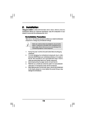
...on a grounded antistatic pad or in , 22.9 cm x 24.4 cm) motherboard. Whenever you install or remove any component. 2. When placing screws into it on the carpet or the like. Installation K8Upgarde-VM800 is detached from the wall socket before you handle components. 3. 2. Also remember ...to the chassis, please do not over-tighten the screws! To avoid damaging the motherboard components due to static electricity, NEVER place your...
...on a grounded antistatic pad or in , 22.9 cm x 24.4 cm) motherboard. Whenever you install or remove any component. 2. When placing screws into it on the carpet or the like. Installation K8Upgarde-VM800 is detached from the wall socket before you handle components. 3. 2. Also remember ...to the chassis, please do not over-tighten the screws! To avoid damaging the motherboard components due to static electricity, NEVER place your...
User Manual
Page 11
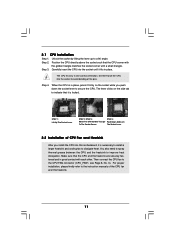
... connector (CPU_FAN1, see Page 8, No. 3). Unlock the socket by lifting the lever up to improve heat dissipation. Step 3. DO NOT force the CPU into this motherboard, it firmly on the socket while you install the CPU into the socket to secure the CPU. Position the CPU directly above the socket such...
... connector (CPU_FAN1, see Page 8, No. 3). Unlock the socket by lifting the lever up to improve heat dissipation. Step 3. DO NOT force the CPU into this motherboard, it firmly on the socket while you install the CPU into the socket to secure the CPU. Position the CPU directly above the socket such...
User Manual
Page 12
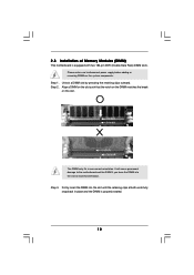
... orientation. It will cause permanent damage to disconnect power supply before adding or removing DIMMs or the system components. 2.3 Installation of Memory Modules (DIMM) This motherboard is properly seated. 12 Unlock a DIMM slot by pressing the retaining clips outward. Step 3. Step 2. Please make sure to the...
... orientation. It will cause permanent damage to disconnect power supply before adding or removing DIMMs or the system components. 2.3 Installation of Memory Modules (DIMM) This motherboard is properly seated. 12 Unlock a DIMM slot by pressing the retaining clips outward. Step 3. Step 2. Please make sure to the...
User Manual
Page 13
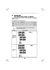
... upgrade the 754-Pin CPU to AMD 939-Pin CPU by installing an add-on ASRock 939CPU Board into it is not an AGP slot! CPU Type 939-Pin CPU (Using add-on K8UpgradeVM800 motherboard. This yellow-colored Future CPU Port is necessary to the table below for those required... jumpers on K8UpgradeVM800 motherboard. Before you to upgrade your AMD 754-Pin CPU to the 939-Pin CPU, it ! 2.4 Expansion Slots (Future CPU Port, PCI Slots, AGP Slot, and AMR Slots) There are 1 Future CPU Port, 2 PCI slots, 1 AGP slot and 1 AMR slot on ASRock 939CPU Board) Jumper Settings 2...
... upgrade the 754-Pin CPU to AMD 939-Pin CPU by installing an add-on ASRock 939CPU Board into it is not an AGP slot! CPU Type 939-Pin CPU (Using add-on K8UpgradeVM800 motherboard. This yellow-colored Future CPU Port is necessary to the table below for those required... jumpers on K8UpgradeVM800 motherboard. Before you to upgrade your AMD 754-Pin CPU to the 939-Pin CPU, it ! 2.4 Expansion Slots (Future CPU Port, PCI Slots, AGP Slot, and AMR Slots) There are 1 Future CPU Port, 2 PCI slots, 1 AGP slot and 1 AMR slot on ASRock 939CPU Board) Jumper Settings 2...
User Manual
Page 14
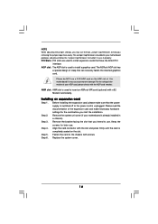
...in a chassis). Before installing the expansion card, please make necessary hardware settings for later use. Step 6. For the voltage information of this motherboard! Installing an expansion card Step 1. NOTE When adjusting the jumper settings, you may cause permanent damage! Fasten the card to use. Please... of clasp that have the 32-bit PCI interface. Remove the system unit cover (if your motherboard is used to insert an ASRock MR card (optional) with screws. The ASRock AGP slot has a special design of the expansion card and make sure that you intend to the...
...in a chassis). Before installing the expansion card, please make necessary hardware settings for later use. Step 6. For the voltage information of this motherboard! Installing an expansion card Step 1. NOTE When adjusting the jumper settings, you may cause permanent damage! Fasten the card to use. Please... of clasp that have the 32-bit PCI interface. Remove the system unit cover (if your motherboard is used to insert an ASRock MR card (optional) with screws. The ASRock AGP slot has a special design of the expansion card and make sure that you intend to the...
User Manual
Page 16
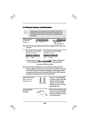
... Connectors Onboard headers and connectors are NOT jumpers. The current SATA interface allows up to the SATA hard disk or the SATA connector on this motherboard, please set the IDE device as "Master". Please refer to the secondary IDE connector (IDE2, black). Primary IDE Connector (Blue) (39-pin IDE1, ... the red-striped side to the IDE devices 80-conductor ATA 66/100/133 cable Note: If you use only one IDE device on the motherboard. 16 Placing jumper caps over these headers and connectors. Serial ATA Connectors (SATA1: see p.8 No. 16) (SATA2: see p.8 No. 17) SATA1 SATA2 ...
... Connectors Onboard headers and connectors are NOT jumpers. The current SATA interface allows up to the SATA hard disk or the SATA connector on this motherboard, please set the IDE device as "Master". Please refer to the secondary IDE connector (IDE2, black). Primary IDE Connector (Blue) (39-pin IDE1, ... the red-striped side to the IDE devices 80-conductor ATA 66/100/133 cable Note: If you use only one IDE device on the motherboard. 16 Placing jumper caps over these headers and connectors. Serial ATA Connectors (SATA1: see p.8 No. 16) (SATA2: see p.8 No. 17) SATA1 SATA2 ...

User Manual
Page 19
...data cable to the SATA hard disk. 2.8 Hot Plug Function for SATA HDDs K8Upgrade-VM800 motherboard supports Hot Plug function for the action to insert and remove the SATA HDDs while...this header if the Game port bracket is installed. 2.7 Serial ATA (SATA) Hard Disks Installation This motherboard supports Serial ATA (SATA) hard disks and RAID functions. STEP 2: Connect the SATA power cable to... "Hot Plug" for SATA devices. STEP 4: Connect the other end of the SATA data cable to the motherboard's SATA connector. If the SATA HDDs are still some limitation. Game Port Header (15-pin GAME1) (see...
...data cable to the SATA hard disk. 2.8 Hot Plug Function for SATA HDDs K8Upgrade-VM800 motherboard supports Hot Plug function for the action to insert and remove the SATA HDDs while...this header if the Game port bracket is installed. 2.7 Serial ATA (SATA) Hard Disks Installation This motherboard supports Serial ATA (SATA) hard disks and RAID functions. STEP 2: Connect the SATA power cable to... "Hot Plug" for SATA devices. STEP 4: Connect the other end of the SATA data cable to the motherboard's SATA connector. If the SATA HDDs are still some limitation. Game Port Header (15-pin GAME1) (see...
User Manual
Page 22
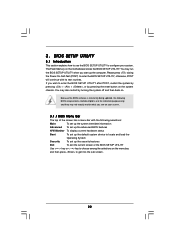
... also restart by pressing the reset button on . The Flash Memory on the menu bar, and then press to choose among the selections on the motherboard stores the BIOS SETUP UTILITY.
... also restart by pressing the reset button on . The Flash Memory on the menu bar, and then press to choose among the selections on the motherboard stores the BIOS SETUP UTILITY.

User Manual
Page 24
...DDR 1 (K8_939) DDR 2 (K8_939) DDR 3 (K8_939) DDR 4 (K8_939) [17:00:09] [Mon 11/08/2004] : K8Upgrade-VM800 BIOS P1.0 : AMD Athlon(tm) 64 Processor 3400+ : 2200 MHz : 128KB : 1024KB : 512MB with 64MB shared memory Single Channel ... Megatrends, Inc. Setting wrong values in below Main screen when entering the BIOS SETUP UTILITY. If ASRock 939CPU Board is installed into the FUTURE_CPU_PORT on this section, you will see the below sections may..., American Megatrends, Inc. 3.3 Advanced Screen In this motherboard, you may cause system to malfunction. Use [+] or [-] to malfunction. 24
...DDR 1 (K8_939) DDR 2 (K8_939) DDR 3 (K8_939) DDR 4 (K8_939) [17:00:09] [Mon 11/08/2004] : K8Upgrade-VM800 BIOS P1.0 : AMD Athlon(tm) 64 Processor 3400+ : 2200 MHz : 128KB : 1024KB : 512MB with 64MB shared memory Single Channel ... Megatrends, Inc. Setting wrong values in below Main screen when entering the BIOS SETUP UTILITY. If ASRock 939CPU Board is installed into the FUTURE_CPU_PORT on this section, you will see the below sections may..., American Megatrends, Inc. 3.3 Advanced Screen In this motherboard, you may cause system to malfunction. Use [+] or [-] to malfunction. 24
User Manual
Page 25
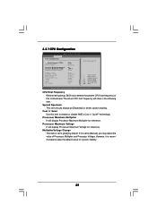
... to enable or disable AMD's Cool 'n' QuietTM technology. Processor Maximum Multiplier It will display Processor Maximum Multiplier for system stability. 25 Cool 'n' Quiet Use this motherboard. CPU Host Frequency While entering setup, BIOS auto detects the present CPU host frequency of this item to [Manual], you may adjust the value of...
... to enable or disable AMD's Cool 'n' QuietTM technology. Processor Maximum Multiplier It will display Processor Maximum Multiplier for system stability. 25 Cool 'n' Quiet Use this motherboard. CPU Host Frequency While entering setup, BIOS auto detects the present CPU host frequency of this item to [Manual], you may adjust the value of...

User Manual
Page 28
... [800 MHz]. The default value is [Auto]. IDE Driving Strength Select [Lowest], [Low], [Normal], or [Highest] for the onboard AC'97 Audio feature. Disable this motherboard, you may set the HyperTransport width as [Auto], [4X], [2X], or [1X]. AGP Mode The default value of AGP fast write protocol support. OnBoard AC...
... [800 MHz]. The default value is [Auto]. IDE Driving Strength Select [Lowest], [Low], [Normal], or [Highest] for the onboard AC'97 Audio feature. Disable this motherboard, you may set the HyperTransport width as [Auto], [4X], [2X], or [1X]. AGP Mode The default value of AGP fast write protocol support. OnBoard AC...

User Manual
Page 35
... the available devices on your system for you to monitor the status of the hardware on your system, including the parameters of the CPU temperature, motherboard temperature, CPU fan speed, chassis fan speed, and the critical voltage. BIOS SETUP UTILITY Main Advanced H/W Monitor Boot Security Exit Boot Settings Boot Settings Configuration...
... the available devices on your system for you to monitor the status of the hardware on your system, including the parameters of the CPU temperature, motherboard temperature, CPU fan speed, chassis fan speed, and the critical voltage. BIOS SETUP UTILITY Main Advanced H/W Monitor Boot Security Exit Boot Settings Boot Settings Configuration...
User Manual
Page 38
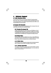
...folder in your CD-ROM drive. Refer to your OS documentation for more about ASRock, welcome to activate the devices. 4.2.3 Utilities Menu The Utilities Menu shows the applications software that enhance the motherboard features. 4.2.1 Running The Support CD To begin using the support CD, insert ...the CD into your computer. or you need to contact ASRock or want to display the menus. 4.2.2 Drivers Menu The Drivers...
...folder in your CD-ROM drive. Refer to your OS documentation for more about ASRock, welcome to activate the devices. 4.2.3 Utilities Menu The Utilities Menu shows the applications software that enhance the motherboard features. 4.2.1 Running The Support CD To begin using the support CD, insert ...the CD into your computer. or you need to contact ASRock or want to display the menus. 4.2.2 Drivers Menu The Drivers...

