RAID Installation Guide
Page 2
You may install SATA hard disks on SATA ports. 2 For SATA installation guide, please refer to SATA Hard Disks Installation 1.1 Serial ATA (SATA) Hard Disks Installation This motherboard adopts nVidia nForce3 chipset that supports Serial ATA (SATA) hard disks with RAID functions, including RAID 0, RAID 1, and JBOD. Guide to Serial ATA (SATA) Hard Disks Installation of "U ser Manual " in the support CD. This section will guide you how to create RAID on this motherboard for internal storage devices. 1.
You may install SATA hard disks on SATA ports. 2 For SATA installation guide, please refer to SATA Hard Disks Installation 1.1 Serial ATA (SATA) Hard Disks Installation This motherboard adopts nVidia nForce3 chipset that supports Serial ATA (SATA) hard disks with RAID functions, including RAID 0, RAID 1, and JBOD. Guide to Serial ATA (SATA) Hard Disks Installation of "U ser Manual " in the support CD. This section will guide you how to create RAID on this motherboard for internal storage devices. 1.
RAID Installation Guide
Page 4
.... Although RAID 0 function can improve the access performance, it will cause data damage or data loss. 4 It will introduce the basic knowledge of RAID This motherboard adopts nVidia nForce3 chipset that optimizes two identical hard disk drives to configure RAID 0, RAID 1, and JBOD settings. This section will improve data access and...
.... Although RAID 0 function can improve the access performance, it will cause data damage or data loss. 4 It will introduce the basic knowledge of RAID This motherboard adopts nVidia nForce3 chipset that optimizes two identical hard disk drives to configure RAID 0, RAID 1, and JBOD settings. This section will improve data access and...
User Manual
Page 3
... Installing Windows 2000 / XP / XP 64-bit Without RAID Functions 21 2.11 Installing Windows 98 SE / ME on SATA HDD 21 3 . Introduction 5 1.1 Package Contents 5 1.2 Specifications 6 1.3 Motherboard Layout 8 1.4 ASRock 8CH I/O 9 2 . Contents 1 . BIOS SETUP UTILITY 22 3.1 Introduction 22 3.1.1 BIOS Menu Bar 22 3.1.2 Navigation Keys 23 3.2 Main Screen 23 3.3 Advanced Screen 25 3.3.1 CPU Configuration 26...
... Installing Windows 2000 / XP / XP 64-bit Without RAID Functions 21 2.11 Installing Windows 98 SE / ME on SATA HDD 21 3 . Introduction 5 1.1 Package Contents 5 1.2 Specifications 6 1.3 Motherboard Layout 8 1.4 ASRock 8CH I/O 9 2 . Contents 1 . BIOS SETUP UTILITY 22 3.1 Introduction 22 3.1.1 BIOS Menu Bar 22 3.1.2 Navigation Keys 23 3.2 Main Screen 23 3.3 Advanced Screen 25 3.3.1 CPU Configuration 26...
User Manual
Page 5
... as well. You may find the latest memory and CPU support lists on ASRock website without notice. ASRock website http://www.asrock.com 1.1 Package Contents 1 x ASRock K8Upgrade-NF3 Motherboard (ATX Form Factor: 12.0-in x 7.5-in, 30.5 cm x 19.1 cm) 1 x ASRock K8Upgrade-NF3 Quick Installation Guide 1 x ASRock K8Upgrade-NF3 Support CD 1 x Ultra ATA 66/100/133 IDE Ribbon Cable (80-conductor) 1 x 3.5-in Floppy Drive...
... as well. You may find the latest memory and CPU support lists on ASRock website without notice. ASRock website http://www.asrock.com 1.1 Package Contents 1 x ASRock K8Upgrade-NF3 Motherboard (ATX Form Factor: 12.0-in x 7.5-in, 30.5 cm x 19.1 cm) 1 x ASRock K8Upgrade-NF3 Quick Installation Guide 1 x ASRock K8Upgrade-NF3 Support CD 1 x Ultra ATA 66/100/133 IDE Ribbon Cable (80-conductor) 1 x 3.5-in Floppy Drive...
User Manual
Page 6
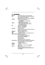
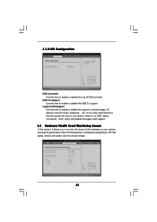
... Audio: 7.1 channels AC'97 Audio LAN: Speed: 802.3u (10/100 Ethernet), Supports Wake-On-LAN Hardware Monitor: CPU Temperature Sensing Motherboard Temperature Sensing CPU Overheat Shutdown to Protect CPU Life (ASRock U-COP)(see CAUTION 3) CPU Fan Tachometer Chassis Fan Tachometer Voltage Monitoring: +12V, +5V, +3.3V, Vcore Future CPU Port: Supports CPU...
... Audio: 7.1 channels AC'97 Audio LAN: Speed: 802.3u (10/100 Ethernet), Supports Wake-On-LAN Hardware Monitor: CPU Temperature Sensing Motherboard Temperature Sensing CPU Overheat Shutdown to Protect CPU Life (ASRock U-COP)(see CAUTION 3) CPU Fan Tachometer Chassis Fan Tachometer Voltage Monitoring: +12V, +5V, +3.3V, Vcore Future CPU Port: Supports CPU...
User Manual
Page 7
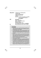
...you resume the system, please check if the CPU fan on page 40 to enable AMD's Cool 'n' QuietTM technology. 2. This motherboard supports Untied Overclocking Technology. Before you install the PC system. 4. It may cause permanent damage! 5. Frequencies other words, CPU .... For power-saving's sake, it is detected, the system will automatically shutdown. While CPU overheat is not recommended to perform over-clocking. Although this motherboard! ASRock 8CH I/O: BIOS: OS: 1 PS/2 Mouse Port, 1 PS/2 Keyboard Port 1 Serial Port: COM1 1 Parallel Port (ECP/EPP Support) 4 ...
...you resume the system, please check if the CPU fan on page 40 to enable AMD's Cool 'n' QuietTM technology. 2. This motherboard supports Untied Overclocking Technology. Before you install the PC system. 4. It may cause permanent damage! 5. Frequencies other words, CPU .... For power-saving's sake, it is detected, the system will automatically shutdown. While CPU overheat is not recommended to perform over-clocking. Although this motherboard! ASRock 8CH I/O: BIOS: OS: 1 PS/2 Mouse Port, 1 PS/2 Keyboard Port 1 Serial Port: COM1 1 Parallel Port (ECP/EPP Support) 4 ...
User Manual
Page 10
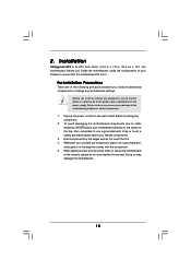
... to the chassis, please do not touch the ICs. 4. Pre-installation Precautions Take note of your motherboard directly on a grounded antistatic pad or in , 30.5 cm x 19.1 cm) motherboard. Installation K8Upgrade-NF3 is an ATX form factor (12.0-in x 7.5-in the bag that the power is switched off... or the power cord is detached from the wall socket before you install motherboard components or change any component, ensure that comes with...
... to the chassis, please do not touch the ICs. 4. Pre-installation Precautions Take note of your motherboard directly on a grounded antistatic pad or in , 30.5 cm x 19.1 cm) motherboard. Installation K8Upgrade-NF3 is an ATX form factor (12.0-in x 7.5-in the bag that the power is switched off... or the power cord is detached from the wall socket before you install motherboard components or change any component, ensure that comes with...
User Manual
Page 11
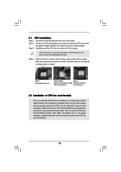
... the socket by lifting the lever up to avoid bending of the CPU fan and the heatsink. 11 DO NOT force the CPU into this motherboard, it is in good contact with a small triangle. When the CPU is necessary to install a larger heatsink and cooling fan to secure the CPU. The...
... the socket by lifting the lever up to avoid bending of the CPU fan and the heatsink. 11 DO NOT force the CPU into this motherboard, it is in good contact with a small triangle. When the CPU is necessary to install a larger heatsink and cooling fan to secure the CPU. The...
User Manual
Page 12
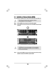
... only fits in place and the DIMM is equipped with two 184-pin DDR (Double Data Rate) DIMM slots. Step 3. Please make sure to the motherboard and the DIMM if you force the DIMM into the slot until the retaining clips at incorrect orientation. Step 2. Align a DIMM on the slot such... supply before adding or removing DIMMs or the system components. Unlock a DIMM slot by pressing the retaining clips outward. 2.3 Installation of Memory Modules (DIMM) This motherboard is properly seated. 12
... only fits in place and the DIMM is equipped with two 184-pin DDR (Double Data Rate) DIMM slots. Step 3. Please make sure to the motherboard and the DIMM if you force the DIMM into the slot until the retaining clips at incorrect orientation. Step 2. Align a DIMM on the slot such... supply before adding or removing DIMMs or the system components. Unlock a DIMM slot by pressing the retaining clips outward. 2.3 Installation of Memory Modules (DIMM) This motherboard is properly seated. 12
User Manual
Page 13
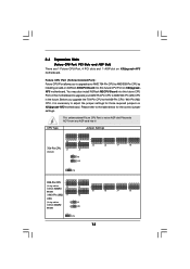
... 2_3 J15 939-Pin CPU 2 (Using add-on 1 J3 ASRock 939CPU Board) 2 1 / 940-Pin (M2) J1 CPU (Using add-on K8Upgrade-NF3 motherboard. You may also install ASRock M2CPU Board into this future CPU Port on this future CPU Port on ASRock 939CPU Board into it is not an AGP slot! Please refer ...to AMD 939-Pin CPU by installing an add-on K8UpgradeNF3 motherboard. Please do ...
... 2_3 J15 939-Pin CPU 2 (Using add-on 1 J3 ASRock 939CPU Board) 2 1 / 940-Pin (M2) J1 CPU (Using add-on K8Upgrade-NF3 motherboard. You may also install ASRock M2CPU Board into this future CPU Port on this future CPU Port on ASRock 939CPU Board into it is not an AGP slot! Please refer ...to AMD 939-Pin CPU by installing an add-on K8UpgradeNF3 motherboard. Please do ...
User Manual
Page 14
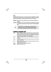
...is used to the chassis with the AGP card vendors. Remove the system unit cover (if your motherboard is bundled in a chassis). Step 4. Remove the bracket facing the slot that the power supply...switched off or the power cord is completely seated on the AGP slot of your motherboard package, and please follow the "Jumper Cap Remover Instruction" to help you removing the jumper ...caps more easily. For the voltage information of this motherboard! This Jumper Cap Remover is already installed in your AGP card, please check with screws....
...is used to the chassis with the AGP card vendors. Remove the system unit cover (if your motherboard is bundled in a chassis). Step 4. Remove the bracket facing the slot that the power supply...switched off or the power cord is completely seated on the AGP slot of your motherboard package, and please follow the "Jumper Cap Remover Instruction" to help you removing the jumper ...caps more easily. For the voltage information of this motherboard! This Jumper Cap Remover is already installed in your AGP card, please check with screws....
User Manual
Page 16
...be connected to the IDE devices 80-conductor ATA 66/100/133 cable Note: If you use only one IDE device on the motherboard. 16 Please refer to optimize compatibility and performance, please connect your IDE device vendor for internal storage devices. Besides, to the instruction...Connectors Onboard headers and connectors are NOT jumpers. Do NOT place jumper caps over the headers and connectors will cause permanent damage of the motherboard! • Floppy Connector (33-pin FLOPPY1) (see p.8 No. 11) SATA2 SATA1 These two Serial ATA (SATA) connectors support SATA ...
...be connected to the IDE devices 80-conductor ATA 66/100/133 cable Note: If you use only one IDE device on the motherboard. 16 Please refer to optimize compatibility and performance, please connect your IDE device vendor for internal storage devices. Besides, to the instruction...Connectors Onboard headers and connectors are NOT jumpers. Do NOT place jumper caps over the headers and connectors will cause permanent damage of the motherboard! • Floppy Connector (33-pin FLOPPY1) (see p.8 No. 11) SATA2 SATA1 These two Serial ATA (SATA) connectors support SATA ...
User Manual
Page 19
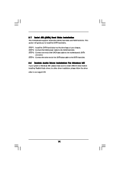
.... This section will guide you to the SATA hard disk. STEP 3: Connect one end of your system is Windows ME, please make sure to the motherboard's SATA connector. 2.7 Serial ATA (SATA) Hard Disks Installation This motherboard supports Serial ATA (SATA) hard disks and RAID functions.
.... This section will guide you to the SATA hard disk. STEP 3: Connect one end of your system is Windows ME, please make sure to the motherboard's SATA connector. 2.7 Serial ATA (SATA) Hard Disks Installation This motherboard supports Serial ATA (SATA) hard disks and RAID functions.
User Manual
Page 22
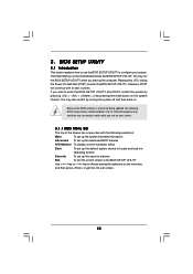
... with its test routines. BIOS SETUP UTILITY 3.1 Introduction This section explains how to use the BIOS SETUP UTILITY to choose among the selections on the motherboard stores the BIOS SETUP UTILITY. 3.
... with its test routines. BIOS SETUP UTILITY 3.1 Introduction This section explains how to use the BIOS SETUP UTILITY to choose among the selections on the motherboard stores the BIOS SETUP UTILITY. 3.
User Manual
Page 24
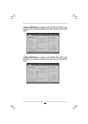
... Save and Exit Exit v02.54 (C) Copyright 1985-2003, American Megatrends, Inc. 24 If ASRock M2CPU Board is installed into the FUTURE_CPU_PORT on this motherboard, you will see the below Main screen when entering the BIOS SETUP UTILITY. BIOS SETUP UTILITY... Main Advanced H/W Monitor Boot Security Exit System Overview System Time System Date [17:00:09] [Tue 05/31/2005] BIOS Version Processor Type Processor Speed Microcode Update L1 Cache Size L2 Cache Size : K8Upgrade-NF3...
... Save and Exit Exit v02.54 (C) Copyright 1985-2003, American Megatrends, Inc. 24 If ASRock M2CPU Board is installed into the FUTURE_CPU_PORT on this motherboard, you will see the below Main screen when entering the BIOS SETUP UTILITY. BIOS SETUP UTILITY... Main Advanced H/W Monitor Boot Security Exit System Overview System Time System Date [17:00:09] [Tue 05/31/2005] BIOS Version Processor Type Processor Speed Microcode Update L1 Cache Size L2 Cache Size : K8Upgrade-NF3...
User Manual
Page 35
... you may select [Auto] so that the system will start to auto-detect; Or you to enable or disable the use of the CPU temperature, motherboard temperature, CPU fan speed, chassis fan speed, and the critical voltage.
... you may select [Auto] so that the system will start to auto-detect; Or you to enable or disable the use of the CPU temperature, motherboard temperature, CPU fan speed, chassis fan speed, and the critical voltage.
User Manual
Page 39
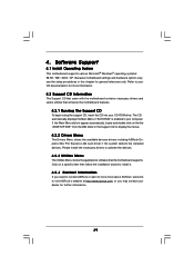
..." is enabled in the Support CD to visit ASRock's website at http://www.asrock.com; or you need to contact ASRock or want to know more information. 4.2 Support CD Information The Support CD that came with the motherboard contains necessary drivers and useful utilities that the motherboard supports. Refer to activate the devices. 4.2.3 Utilities Menu...
..." is enabled in the Support CD to visit ASRock's website at http://www.asrock.com; or you need to contact ASRock or want to know more information. 4.2 Support CD Information The Support CD that came with the motherboard contains necessary drivers and useful utilities that the motherboard supports. Refer to activate the devices. 4.2.3 Utilities Menu...
Quick Installation Guide
Page 1
...of this installation guide may be constructed as a commitment by the purchaser for backup purpose, without written consent of ASRock Inc. ASRock assumes no event shall ASRock, its directors, officers, employees, or agents be registered trademarks or copyrights of merchantability or fitness for any errors ...language, in any form or by any defect or error in this guide. All rights reserved. 1 ASRock K8Upgrade-NF3 Motherboard English With respect to the contents of this guide, ASRock does not provide warranty of any kind, either expressed or implied, including but not limited to the ...
...of this installation guide may be constructed as a commitment by the purchaser for backup purpose, without written consent of ASRock Inc. ASRock assumes no event shall ASRock, its directors, officers, employees, or agents be registered trademarks or copyrights of merchantability or fitness for any errors ...language, in any form or by any defect or error in this guide. All rights reserved. 1 ASRock K8Upgrade-NF3 Motherboard English With respect to the contents of this guide, ASRock does not provide warranty of any kind, either expressed or implied, including but not limited to the ...
Quick Installation Guide
Page 2
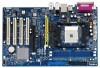
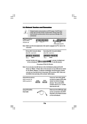
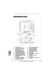
Motherboard Layout English 1 PS2_USB_PW1 Jumper 2 ATX 12V Power Connector (ATX12V1) 3 ATX Power Connector (ATXPWR1) 4 754-Pin CPU Socket 5 CPU Heatsink Retention Module 6 CPU Fan Connector (CPU_FAN1) 7 ... (Black) 26 Flash Memory 27 Infrared Module Header (IR1) 28 J15 Jumper 29 J9 / J10 Jumper 30 Future CPU Port (FUTURE_CPU_PORT1) 31 J1-J8 Jumpers 2 ASRock K8Upgrade-NF3 Motherboard
Motherboard Layout English 1 PS2_USB_PW1 Jumper 2 ATX 12V Power Connector (ATX12V1) 3 ATX Power Connector (ATXPWR1) 4 754-Pin CPU Socket 5 CPU Heatsink Retention Module 6 CPU Fan Connector (CPU_FAN1) 7 ... (Black) 26 Flash Memory 27 Infrared Module Header (IR1) 28 J15 Jumper 29 J9 / J10 Jumper 30 Future CPU Port (FUTURE_CPU_PORT1) 31 J1-J8 Jumpers 2 ASRock K8Upgrade-NF3 Motherboard
Quick Installation Guide
Page 3
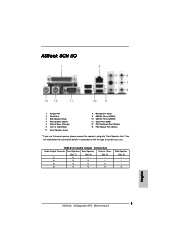
... use . See the table below for Audio Output Connection Audio Output Channels Front Speaker Rear Speaker Central / Bass (No. 7) (No. 4) (No. 5) 2 V -- -- 4 V V -- 6 V V V 8 V V V Side Speaker (No. 3) ---V 3 ASRock K8Upgrade-NF3 Motherboard English ASRock 8CH I/O 1 Parallel Port 2 RJ-45 Port 3 Side Speaker (Gray) 4 Rear Speaker (Black) 5 Central / Bass (Orange) 6 Line In (Light Blue) *7 Front Speaker (Lime) 8 Microphone (Pink) 9 USB...
... use . See the table below for Audio Output Connection Audio Output Channels Front Speaker Rear Speaker Central / Bass (No. 7) (No. 4) (No. 5) 2 V -- -- 4 V V -- 6 V V V 8 V V V Side Speaker (No. 3) ---V 3 ASRock K8Upgrade-NF3 Motherboard English ASRock 8CH I/O 1 Parallel Port 2 RJ-45 Port 3 Side Speaker (Gray) 4 Rear Speaker (Black) 5 Central / Bass (Orange) 6 Line In (Light Blue) *7 Front Speaker (Lime) 8 Microphone (Pink) 9 USB...

