User Manual
Page 3
... UTILITY 33 3.1 Introduction 33 3.1.1 BIOS Menu Bar 33 3.1.2 Navigation Keys 34 3.2 Main Screen 34 3 Installation 13 Pre-installation Precautions 13 2.1 CPU Installation 14 2.2 Installation of CPU Fan and Heatsink 14 2.3 ...
... UTILITY 33 3.1 Introduction 33 3.1.1 BIOS Menu Bar 33 3.1.2 Navigation Keys 34 3.2 Main Screen 34 3 Installation 13 Pre-installation Precautions 13 2.1 CPU Installation 14 2.2 Installation of CPU Fan and Heatsink 14 2.3 ...
User Manual
Page 5
... x 7.5-in, 30.5 cm x 19.1 cm) ASRock K10N78D Quick Installation Guide ASRock K10N78D Support CD One 80-conductor Ultra ATA 66/100/133 IDE Ribbon Cable Two Serial ATA (SATA) Data Cables (Optional) One Serial ATA (SATA) HDD Power Cable (Optional) One I/O Panel Shield 5 Because the motherboard specifications and the BIOS software might be updated, the...
... x 7.5-in, 30.5 cm x 19.1 cm) ASRock K10N78D Quick Installation Guide ASRock K10N78D Support CD One 80-conductor Ultra ATA 66/100/133 IDE Ribbon Cable Two Serial ATA (SATA) Data Cables (Optional) One Serial ATA (SATA) HDD Power Cable (Optional) One I/O Panel Shield 5 Because the motherboard specifications and the BIOS software might be updated, the...

User Manual
Page 7
...Feature - CPU Quiet Fan - AMI Legal BIOS - Supports Smart BIOS Support CD - Hybrid Booster: - Voltage Monitoring: +12V, +5V, +3.3V, CPU Vcore OS - CD in header - NB Voltage Multi-adjustment - ASRock AM2 Boost: ASRock Patented Technology to boost memory performance up to ... connector - Front panel audio connector - 3 x USB 2.0 headers (support 6 USB 2.0 ports) (see CAUTION 10) - ASRock Instant Flash (see CAUTION 7) BIOS Feature - 8Mb AMI BIOS - CPU/Chassis/NB Fan Tachometer - Intelligent Energy Saver (see CAUTION 9) - Supports "Plug and Play" - FCC, CE,...
...Feature - CPU Quiet Fan - AMI Legal BIOS - Supports Smart BIOS Support CD - Hybrid Booster: - Voltage Monitoring: +12V, +5V, +3.3V, CPU Vcore OS - CD in header - NB Voltage Multi-adjustment - ASRock AM2 Boost: ASRock Patented Technology to boost memory performance up to ... connector - Front panel audio connector - 3 x USB 2.0 headers (support 6 USB 2.0 ports) (see CAUTION 10) - ASRock Instant Flash (see CAUTION 7) BIOS Feature - 8Mb AMI BIOS - CPU/Chassis/NB Fan Tachometer - Intelligent Energy Saver (see CAUTION 9) - Supports "Plug and Play" - FCC, CE,...
User Manual
Page 8
... under Windows® environment. You can also connect SATA hard disk to the components and devices of your system by overclocking. ASRock website: http://www.asrock.com 8 It should be less than 4GB for the reservation for USB 2.0 works fine under Windows® XP and Windows...Overclocking Technology. For Windows® XP 64-bit and Windows® VistaTM 64-bit with overclocking, including adjusting the setting in the BIOS, applying Untied Overclocking Technology, or using the thirdparty overclocking tools. For audio output, this motherboard supports both stereo and mono modes. ...
... under Windows® environment. You can also connect SATA hard disk to the components and devices of your system by overclocking. ASRock website: http://www.asrock.com 8 It should be less than 4GB for the reservation for USB 2.0 works fine under Windows® XP and Windows...Overclocking Technology. For Windows® XP 64-bit and Windows® VistaTM 64-bit with overclocking, including adjusting the setting in the BIOS, applying Untied Overclocking Technology, or using the thirdparty overclocking tools. For audio output, this motherboard supports both stereo and mono modes. ...

User Manual
Page 9
... please check if the CPU fan on the AM2 CPU you enable this tool and save the new BIOS file to your USB flash drive, floppy disk or hard drive, then you to access ASRock Instant Flash. If you adopt. The voltage regulator can press key during the POST or press key... to BIOS setup menu to update system BIOS without sacrificing computing performance. You may choose to provide exceptional power saving and ...
... please check if the CPU fan on the AM2 CPU you enable this tool and save the new BIOS file to your USB flash drive, floppy disk or hard drive, then you to access ASRock Instant Flash. If you adopt. The voltage regulator can press key during the POST or press key... to BIOS setup menu to update system BIOS without sacrificing computing performance. You may choose to provide exceptional power saving and ...
User Manual
Page 10
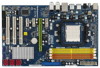
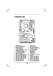
... 10 SATAII Connector (SATAII_6 (PORT 5), Red) 27 Internal Audio Connector: CD1 (Black) 11 SATAII Connector (SATAII_5 (PORT 4), Red) 28 SPI BIOS Chip 12 SATAII Connector (SATAII_4 (PORT 3), Red) 29 PCI Express x1 Slot (PCIE4, White) 13 SATAII Connector (SATAII_3 (PORT 2), Red) ...IN Center: FRONT Bottom: MIC IN CHA_FAN1 CPU_FAN1 Phenom II AM2+/AM3 LAN PCIE1 PHY PCIE2 K10N78D PCIE3 PCI Express 2.0 CMOS BATTERY Super I/O CD1 AUDIO CODEC HDMI_SPDIF1 1 HD_AUDIO1 FLOPPY1 1 PCIE4 8Mb BIOS 1 CLRCMOS1 PCI1 RoHS PCI2 NVIDIA nForce 720D Chipset SATAII_6 (PORT 5) SATAII_5 (PORT 4) ...
... 10 SATAII Connector (SATAII_6 (PORT 5), Red) 27 Internal Audio Connector: CD1 (Black) 11 SATAII Connector (SATAII_5 (PORT 4), Red) 28 SPI BIOS Chip 12 SATAII Connector (SATAII_4 (PORT 3), Red) 29 PCI Express x1 Slot (PCIE4, White) 13 SATAII Connector (SATAII_3 (PORT 2), Red) ...IN Center: FRONT Bottom: MIC IN CHA_FAN1 CPU_FAN1 Phenom II AM2+/AM3 LAN PCIE1 PHY PCIE2 K10N78D PCIE3 PCI Express 2.0 CMOS BATTERY Super I/O CD1 AUDIO CODEC HDMI_SPDIF1 1 HD_AUDIO1 FLOPPY1 1 PCIE4 8Mb BIOS 1 CLRCMOS1 PCI1 RoHS PCI2 NVIDIA nForce 720D Chipset SATAII_6 (PORT 5) SATAII_5 (PORT 4) ...

User Manual
Page 18
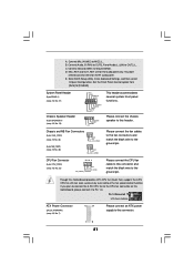
..., the jumper is placed on these 2 pins. Note: To select +5VSB, it down before you do not clear the CMOS right after you update the BIOS. Clear CMOS Jumper (CLRCMOS1) (see p.10, No. 1) +5V +5VSB +5VSB (standby) for 5 seconds. If you need to clear the CMOS when you just finish ...updating the BIOS, you to enable (see p.10, No. 30) 1_2 2_3 Default Clear CMOS Note: CLRCMOS1 allows you must boot up events. To clear and reset the...
..., the jumper is placed on these 2 pins. Note: To select +5VSB, it down before you do not clear the CMOS right after you update the BIOS. Clear CMOS Jumper (CLRCMOS1) (see p.10, No. 1) +5V +5VSB +5VSB (standby) for 5 seconds. If you need to clear the CMOS when you just finish ...updating the BIOS, you to enable (see p.10, No. 30) 1_2 2_3 Default Clear CMOS Note: CLRCMOS1 allows you must boot up events. To clear and reset the...
User Manual
Page 21
.... Please connect the chassis speaker to this motherboard, please connect it to Pin 1-3. A. You don't need to the CPU fan connector on this header. Enter BIOS Setup Utility. Set the Front Panel Control option from [Auto] to MIC2_L. If you plan to connect the 3-Pin CPU fan to connect them for...
.... Please connect the chassis speaker to this motherboard, please connect it to Pin 1-3. A. You don't need to the CPU fan connector on this header. Enter BIOS Setup Utility. Set the Front Panel Control option from [Auto] to MIC2_L. If you plan to connect the 3-Pin CPU fan to connect them for...
User Manual
Page 28
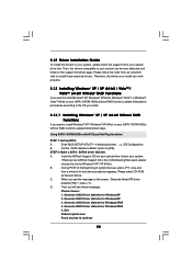
...HDDs without RAID functions, please follow the order from up , press key, and then a window for boot devices selection appears. Enter BIOS SETUP UTILITY Advanced screen IDE Configuration. A. Generate RAID Driver diskette for WindowsXP 2. Then, the drivers compatible to your SATA / SATAII HDDs... 28 When you will see the message on the support CD driver page. D. Generate AHCI Driver diskette for WindowsXP 3. B. Insert the ASRock Support CD into your optical drive to boot your optical drive first. Then you see these messages, Please choose: 1. STEP 2: Make ...
...HDDs without RAID functions, please follow the order from up , press key, and then a window for boot devices selection appears. Enter BIOS SETUP UTILITY Advanced screen IDE Configuration. A. Generate RAID Driver diskette for WindowsXP 2. Then, the drivers compatible to your SATA / SATAII HDDs... 28 When you will see the message on the support CD driver page. D. Generate AHCI Driver diskette for WindowsXP 3. B. Insert the ASRock Support CD into your optical drive to boot your optical drive first. Then you see these messages, Please choose: 1. STEP 2: Make ...
User Manual
Page 29
...are as below steps. NVIDIA nForce Storage Controller (required) Windows XP64 Please select A for Windows® XP 64-bit in AHCI mode. Enter BIOS SETUP UTILITY Advanced screen IDE Configuration. Please follow the instruction to install Windows? At the beginning of Windows® setup, press F6 to [...-bit Without RAID Functions If you want to install Windows® XP / XP 64-bit on your system. A. " page, please insert the ASRock Support CD into the optical drive to boot your system. You can start to [AHCI]. Set the "SATA Operation Mode" option to the mode ...
...are as below steps. NVIDIA nForce Storage Controller (required) Windows XP64 Please select A for Windows® XP 64-bit in AHCI mode. Enter BIOS SETUP UTILITY Advanced screen IDE Configuration. Please follow the instruction to install Windows? At the beginning of Windows® setup, press F6 to [...-bit Without RAID Functions If you want to install Windows® XP / XP 64-bit on your system. A. " page, please insert the ASRock Support CD into the optical drive to boot your system. You can start to [AHCI]. Set the "SATA Operation Mode" option to the mode ...

User Manual
Page 30
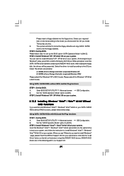
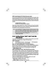
...® VistaTM 64-bit on your SATA / SATAII HDDs with RAID functions, please follow below steps. B. STEP 4: Use "RAID Installation Guide" to the BIOS RAID installation guide part of the document in the following section 2.13.1 step 2 on your system. 2.14 Installing Windows® XP / XP 64-bit... optical disk into the optical drive again to install Windows® XP / Windows® XP 64-bit on page 28. (There are two ASRock Support CD in the motherboard gift box pack, please choose the one for proper configuration. STEP 2: Install Windows® VistaTM / VistaTM 64-bit...
...® VistaTM 64-bit on your SATA / SATAII HDDs with RAID functions, please follow below steps. B. STEP 4: Use "RAID Installation Guide" to the BIOS RAID installation guide part of the document in the following section 2.13.1 step 2 on your system. 2.14 Installing Windows® XP / XP 64-bit... optical disk into the optical drive again to install Windows® XP / Windows® XP 64-bit on page 28. (There are two ASRock Support CD in the motherboard gift box pack, please choose the one for proper configuration. STEP 2: Install Windows® VistaTM / VistaTM 64-bit...
User Manual
Page 31
...function, you need to set RAID configuration. Select the drivers to set up "SATA Operation Mode" to [RAID] in BIOS first. STEP 1: Set Up BIOS. Please refer to the BIOS RAID installation guide part of Windows® setup, press F6 to [RAID]. STEP 5: Install Windows® XP / ... installation guide in the Support CD for proper configuration. A. B. STEP 2: Use "RAID Installation Guide" to install. " page, please insert the ASRock Support CD into the optical drive to boot your system, and follow the instruction to install Windows® VistaTM / Windows® VistaTM 64-bit ...
...function, you need to set RAID configuration. Select the drivers to set up "SATA Operation Mode" to [RAID] in BIOS first. STEP 1: Set Up BIOS. Please refer to the BIOS RAID installation guide part of Windows® setup, press F6 to [RAID]. STEP 5: Install Windows® XP / ... installation guide in the Support CD for proper configuration. A. B. STEP 2: Use "RAID Installation Guide" to install. " page, please insert the ASRock Support CD into the optical drive to boot your system, and follow the instruction to install Windows® VistaTM / Windows® VistaTM 64-bit ...

User Manual
Page 32
Before you enable Untied Overclocking function, please enter "Overclock Mode" option of BIOS setup to set the selection from [Auto] to continue the installation. After that FSB can operate under a more stable overclocking environment. Then, please ...CD: .. \ RAID Installation Guide 2.15 Untied Overclocking Technology This motherboard supports Untied Overclocking Technology, which means during overclocking, but PCI / PCIE buses are in BIOS first. NOTE. Therefore, CPU FSB is untied during overclocking, FSB enjoys better margin due to [RAID] in the fixed mode so that , please insert ...
Before you enable Untied Overclocking function, please enter "Overclock Mode" option of BIOS setup to set the selection from [Auto] to continue the installation. After that FSB can operate under a more stable overclocking environment. Then, please ...CD: .. \ RAID Installation Guide 2.15 Untied Overclocking Technology This motherboard supports Untied Overclocking Technology, which means during overclocking, but PCI / PCIE buses are in BIOS first. NOTE. Therefore, CPU FSB is untied during overclocking, FSB enjoys better margin due to [RAID] in the fixed mode so that , please insert ...

User Manual
Page 33
...being updated, the following selections: Main To set up the system time/date information Smart To load the BIOS according to your system. If you wish to enter the BIOS SETUP UTILITY after POST, restart the system by pressing + + , or by turning the system off ...to choose among the selections on the motherboard stores the BIOS SETUP UTILITY. BIOS SETUP UTILITY 3.1 Introduction This section explains how to use the BIOS SETUP UTILITY to enter the BIOS SETUP UTILITY, otherwise, POST will continue with the following BIOS setup screens and descriptions are for reference purpose only, ...
...being updated, the following selections: Main To set up the system time/date information Smart To load the BIOS according to your system. If you wish to enter the BIOS SETUP UTILITY after POST, restart the system by pressing + + , or by turning the system off ...to choose among the selections on the motherboard stores the BIOS SETUP UTILITY. BIOS SETUP UTILITY 3.1 Introduction This section explains how to use the BIOS SETUP UTILITY to enter the BIOS SETUP UTILITY, otherwise, POST will continue with the following BIOS setup screens and descriptions are for reference purpose only, ...

User Manual
Page 34
... item to specify the system date. 34 3.1.2Navigation Keys Please check the following table for all the settings To save changes and exit the BIOS SETUP UTILITY To jump to specify the system time. System Date [Day Month/Date/Year] Use this item to the Exit Screen or exit... UTILITY Main Smart Advanced H/W Monitor Boot Security Exit System Overview System Time System Date [17:00:09] [Wed 04/29/2009] BIOS Version : K10N78D P1.0 Processor Type : AMD Phenom (tm) 8650 Triple-Core Processor (64bit) Processor Speed : 2300MHz Microcode Update : 100F23/1000095 L1 Cache Size : 384KB L2 Cache ...
... item to specify the system date. 34 3.1.2Navigation Keys Please check the following table for all the settings To save changes and exit the BIOS SETUP UTILITY To jump to specify the system time. System Date [Day Month/Date/Year] Use this item to the Exit Screen or exit... UTILITY Main Smart Advanced H/W Monitor Boot Security Exit System Overview System Time System Date [17:00:09] [Wed 04/29/2009] BIOS Version : K10N78D P1.0 Processor Type : AMD Phenom (tm) 8650 Triple-Core Processor (64bit) Processor Speed : 2300MHz Microcode Update : 100F23/1000095 L1 Cache Size : 384KB L2 Cache ...

User Manual
Page 35
... this operation. Load Performance Setup AHCI Mode This performance setup AHCI mode may not be used for this operation. ASRock Instant Flash ASRock Instant Flash is a BIOS flash utility embedded in Flash ROM. Just launch this operation. F10 key can be compatible with all system configurations....Performance Setup Default (IDE/SATA) Load Performance Setup AHCI Mode Load Performance Setup RAID Mode Load Power Saving Setup Default BIOS Update Utility ASRock Instant Flash Exit system setup after loading, please resume optimal default settings. Select Screen Select Item Enter Go to Sub...
... this operation. Load Performance Setup AHCI Mode This performance setup AHCI mode may not be used for this operation. ASRock Instant Flash ASRock Instant Flash is a BIOS flash utility embedded in Flash ROM. Just launch this operation. F10 key can be compatible with all system configurations....Performance Setup Default (IDE/SATA) Load Performance Setup AHCI Mode Load Performance Setup RAID Mode Load Power Saving Setup Default BIOS Update Utility ASRock Instant Flash Exit system setup after loading, please resume optimal default settings. Select Screen Select Item Enter Go to Sub...
User Manual
Page 36
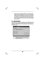
...without preparing an additional floppy diskette or other complicated flash utility. hard drive, then you can update your system after BIOS update process completes. 3.4 Advanced Screen In this section may cause system to malfunction. If you may set the configurations... Advanced H/W Monitor Boot Security Exit Advanced Settings WARNING : Setting wrong values in this section, you execute ASRock Instant Flash utility, the utility will show the BIOS files and their respective information. Options for the following items: CPU Configuration, Memory Configuration, Chipset Configuration, ...
...without preparing an additional floppy diskette or other complicated flash utility. hard drive, then you can update your system after BIOS update process completes. 3.4 Advanced Screen In this section may cause system to malfunction. If you may set the configurations... Advanced H/W Monitor Boot Security Exit Advanced Settings WARNING : Setting wrong values in this section, you execute ASRock Instant Flash utility, the utility will show the BIOS files and their respective information. Options for the following items: CPU Configuration, Memory Configuration, Chipset Configuration, ...
User Manual
Page 37
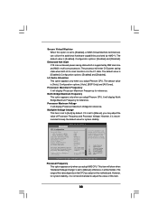
...disable AMD's Cool 'n' QuietTM technology. The default value is [Auto]. Configuration options: [Auto], [Enabled] and [Disabled]. 3.4.1 CPU Configuration BIOS SETUP UTILITY Advanced CPU Configuration Overclock Mode CPU Frequency (MHz) PCIE Frequency (MHz) CPU/LDT Spread Spectrum SATA Spread Spectrum Boot Failure Guard...to adjust CPU frequency. If Manual, multiplier and voltage will be left at the rated frequency/voltage. If you will enable ASRock AM2 Boost function, which will improve the memory performance. The default value is [Disabled]. CPU/LDT Spread Spectrum This feature ...
...disable AMD's Cool 'n' QuietTM technology. The default value is [Auto]. Configuration options: [Auto], [Enabled] and [Disabled]. 3.4.1 CPU Configuration BIOS SETUP UTILITY Advanced CPU Configuration Overclock Mode CPU Frequency (MHz) PCIE Frequency (MHz) CPU/LDT Spread Spectrum SATA Spread Spectrum Boot Failure Guard...to adjust CPU frequency. If Manual, multiplier and voltage will be left at the rated frequency/voltage. If you will enable ASRock AM2 Boost function, which will improve the memory performance. The default value is [Disabled]. CPU/LDT Spread Spectrum This feature ...
User Manual
Page 38
... F9 F10 ESC Select Screen Select Item Change Option General Help Load Defaults Save and Exit Exit v02.54 (C) Copyright 1985-2003, American Megatrends, Inc. BIOS SETUP UTILITY Advanced CPU Configuration Overclock Mode CPU Frequency (MHz) PCIE Frequency (MHz) CPU/LDT Spread Spectrum SATA Spread Spectrum Boot Failure Guard Cool' n' Quiet...
... F9 F10 ESC Select Screen Select Item Change Option General Help Load Defaults Save and Exit Exit v02.54 (C) Copyright 1985-2003, American Megatrends, Inc. BIOS SETUP UTILITY Advanced CPU Configuration Overclock Mode CPU Frequency (MHz) PCIE Frequency (MHz) CPU/LDT Spread Spectrum SATA Spread Spectrum Boot Failure Guard Cool' n' Quiet...

User Manual
Page 40
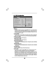
... banks on the same node, or accross nodes, decreasing access contention. Configuration options: [Auto], [3CLK] to enable or disable DDR power down mode. 3.4.2 Memory Configuration BIOS SETUP UTILITY Advanced Memory Configuration Memory Clock Flexibility Option Memory Controller Mode Power Down Enable Bank Interleaving Channel Interleaving Timing : 5-5-5-15 CAS Latency (CL) TRCD...
... banks on the same node, or accross nodes, decreasing access contention. Configuration options: [Auto], [3CLK] to enable or disable DDR power down mode. 3.4.2 Memory Configuration BIOS SETUP UTILITY Advanced Memory Configuration Memory Clock Flexibility Option Memory Controller Mode Power Down Enable Bank Interleaving Channel Interleaving Timing : 5-5-5-15 CAS Latency (CL) TRCD...


