RAID Installation Guide
Page 1
NVIDIA RAID Installation Guide 1. NVIDIA Windows RAID Installation Guide 11 2.1 NVIDIA Windows RAID Installation Guide for Windows XP / XP 64-bit Users 11 2.2 NVIDIA Windows RAID Installation Guide for Windows Vista / Vista 64-bit Users 21 1 NVIDIA BIOS RAID Installation Guide 2 1.1 Introduction to RAID 2 1.2 RAID Configurations Precautions 3 1.3 Installing Windows XP / XP 64-bit / Vista / Vista 64-bit With RAID Functions 5 1.3.1 Installing Windows XP / XP 64-bit With RAID Functions 5 1.3.2 Installing Windows Vista / Vista 64-bit With RAID Functions 7 1.4 Create Disk Array 8 2.
NVIDIA RAID Installation Guide 1. NVIDIA Windows RAID Installation Guide 11 2.1 NVIDIA Windows RAID Installation Guide for Windows XP / XP 64-bit Users 11 2.2 NVIDIA Windows RAID Installation Guide for Windows Vista / Vista 64-bit Users 21 1 NVIDIA BIOS RAID Installation Guide 2 1.1 Introduction to RAID 2 1.2 RAID Configurations Precautions 3 1.3 Installing Windows XP / XP 64-bit / Vista / Vista 64-bit With RAID Functions 5 1.3.1 Installing Windows XP / XP 64-bit With RAID Functions 5 1.3.2 Installing Windows Vista / Vista 64-bit With RAID Functions 7 1.4 Create Disk Array 8 2.
RAID Installation Guide
Page 2
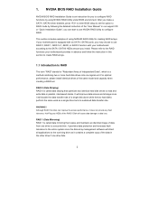
...with six SATA / SATAII ports, you may choose to configure RAID. This section includes examples of using NVIDIA RAID Utility under BIOS environment. NVIDIA BIOS RAID Installation Guide NVIDIA BIOS RAID Installation Guide is a method combining two or more hard disk drives into one drive to configure RAID functions by following ...the disk array management software will cause data damage or data loss. 1. After you make a SATA / SATAII driver diskette, press to enter BIOS setup to read and write data in our support CD or "Quick Installation Guide", you install. WARNING!!
...with six SATA / SATAII ports, you may choose to configure RAID. This section includes examples of using NVIDIA RAID Utility under BIOS environment. NVIDIA BIOS RAID Installation Guide NVIDIA BIOS RAID Installation Guide is a method combining two or more hard disk drives into one drive to configure RAID functions by following ...the disk array management software will cause data damage or data loss. 1. After you make a SATA / SATAII driver diskette, press to enter BIOS setup to read and write data in our support CD or "Quick Installation Guide", you install. WARNING!!
RAID Installation Guide
Page 5
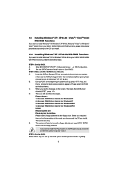
...choose and the OS you see these messages, Please choose: 1. Please follow below steps. Enter BIOS SETUP UTILITY Advanced screen IDE Configuration. STEP 2: Make a SATA / SATAII Driver Diskette. Insert the ASRock Support CD into your optical drive to continue Please insert a floppy diskette into the floppy diskette.... During POST at the beginning of system boot-up the BIOS option "SATA Operation Mode" to [non-RAID]. Please select CD-ROM as the boot device. D. Select your system. (There are two ASRock Support CD in the motherboard gift box pack, please choose the ...
...choose and the OS you see these messages, Please choose: 1. Please follow below steps. Enter BIOS SETUP UTILITY Advanced screen IDE Configuration. STEP 2: Make a SATA / SATAII Driver Diskette. Insert the ASRock Support CD into your optical drive to continue Please insert a floppy diskette into the floppy diskette.... During POST at the beginning of system boot-up the BIOS option "SATA Operation Mode" to [non-RAID]. Please select CD-ROM as the boot device. D. Select your system. (There are two ASRock Support CD in the motherboard gift box pack, please choose the ...
RAID Installation Guide
Page 6
... on your system. Please refer to select them separately. NVIDIA nForce Storage Controller (required) Please select A and B for Windows® XP / XP 64-bit in BIOS first. When prompted, insert the SATA / SATAII driver diskette containing the NVIDIA® RAID driver. The drivers are two RAID drivers needed for the second... one.) NOTE. Please specify the first RAID driver and then specify again for RAID mode, you have to the BIOS RAID installation guide in the following path in the Support CD for proper configuration.
... on your system. Please refer to select them separately. NVIDIA nForce Storage Controller (required) Please select A and B for Windows® XP / XP 64-bit in BIOS first. When prompted, insert the SATA / SATAII driver diskette containing the NVIDIA® RAID driver. The drivers are two RAID drivers needed for the second... one.) NOTE. Please specify the first RAID driver and then specify again for RAID mode, you have to the BIOS RAID installation guide in the following path in the Support CD for proper configuration.
RAID Installation Guide
Page 7
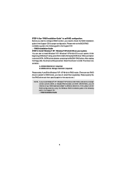
...function, you want to install Windows? NVIDIA® RAID drivers are in the following path in our Support CD: (There are two ASRock Support CD in the motherboard gift box pack, please choose the one for proper configuration. 1.3.2 Installing Windows® VistaTM / VistaTM 64...the "SATA Operation Mode" option to [RAID] in BIOS first. STEP 2: Use "RAID Installation Guide" to continue the installation. Enter BIOS SETUP UTILITY Advanced screen IDE Configuration. Then, please set RAID configuration. " page, please insert the ASRock Support CD into the optical drive again to set ...
...function, you want to install Windows? NVIDIA® RAID drivers are in the following path in our Support CD: (There are two ASRock Support CD in the motherboard gift box pack, please choose the one for proper configuration. 1.3.2 Installing Windows® VistaTM / VistaTM 64...the "SATA Operation Mode" option to [RAID] in BIOS first. STEP 2: Use "RAID Installation Guide" to continue the installation. Enter BIOS SETUP UTILITY Advanced screen IDE Configuration. Then, please set RAID configuration. " page, please insert the ASRock Support CD into the optical drive again to set ...
RAID Installation Guide
Page 8
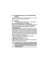
After adjusting the system BIOS to press before the window disappears. You have a few seconds to RAID mode, the below window appears. And the Striping Block is set to Mirroring, ...
After adjusting the system BIOS to press before the window disappears. You have a few seconds to RAID mode, the below window appears. And the Striping Block is set to Mirroring, ...
RAID Installation Guide
Page 9
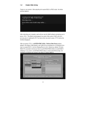
Move it from the RAID Config BIOS setup page appear in kilobytes, and affect how data is arranged on the disk. Continue pressing the right-arrow key until all the disks that ...
Move it from the RAID Config BIOS setup page appear in kilobytes, and affect how data is arranged on the disk. Continue pressing the right-arrow key until all the disks that ...
RAID Installation Guide
Page 12
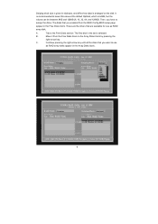
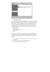
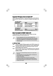
... / SATAII ports, you want to use NVRAIDMAN to create RAID 0 (Striping). If you install. C. Create Array and the following : A. RAID 0: Striping - Go to the system BIOS and make sure that the drives that you may be mentioned in this section are similar to create RAID arrays. RAID 1: Mirroring - RAID 0+1: Stripe Mirroring...
... / SATAII ports, you want to use NVRAIDMAN to create RAID 0 (Striping). If you install. C. Create Array and the following : A. RAID 0: Striping - Go to the system BIOS and make sure that the drives that you may be mentioned in this section are similar to create RAID arrays. RAID 1: Mirroring - RAID 0+1: Stripe Mirroring...
User Manual
Page 4
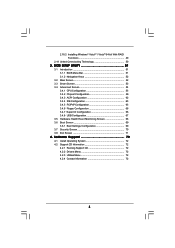
2.18.2 Installing Windows® VistaTM / VistaTM 64-bit With RAID Functions 49 2.19 Untied Overclocking Technology 50 3 . BIOS SETUP UTILITY 51 3.1 Introduction 51 3.1.1 BIOS Menu Bar 51 3.1.2 Navigation Keys 52 3.2 Main Screen 52 3.3 Smart Screen 53 3.4 Advanced Screen 54 3.4.1 CPU Configuration 55 3.4.2 Chipset Configuration 59 3.4.3 ACPI Configuration 62 3.4.4 IDE ...
2.18.2 Installing Windows® VistaTM / VistaTM 64-bit With RAID Functions 49 2.19 Untied Overclocking Technology 50 3 . BIOS SETUP UTILITY 51 3.1 Introduction 51 3.1.1 BIOS Menu Bar 51 3.1.2 Navigation Keys 52 3.2 Main Screen 52 3.3 Smart Screen 53 3.4 Advanced Screen 54 3.4.1 CPU Configuration 55 3.4.2 Chipset Configuration 59 3.4.3 ACPI Configuration 62 3.4.4 IDE ...
User Manual
Page 5
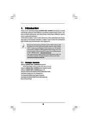
... be subject to the hardware installation. www.asrock.com/support/index.asp 1.1 Package Contents ASRock K10N78-1394 / K10N78 Motherboard (ATX Form Factor: 12.0-in x 8.4-in, 30.5 cm x 21.3 cm) ASRock K10N78-1394 / K10N78 Quick Installation Guide ASRock K10N78-1394 / K10N78 Support CD One 80-conductor Ultra ATA 66...may find the latest VGA cards and CPU support lists on ASRock website without notice. Because the motherboard specifications and the BIOS software might be available on ASRock website as well. ASRock website http://www.asrock.com If you for a 3.5-in Floppy Drive Two Serial ...
... be subject to the hardware installation. www.asrock.com/support/index.asp 1.1 Package Contents ASRock K10N78-1394 / K10N78 Motherboard (ATX Form Factor: 12.0-in x 8.4-in, 30.5 cm x 21.3 cm) ASRock K10N78-1394 / K10N78 Quick Installation Guide ASRock K10N78-1394 / K10N78 Support CD One 80-conductor Ultra ATA 66...may find the latest VGA cards and CPU support lists on ASRock website without notice. Because the motherboard specifications and the BIOS software might be available on ASRock website as well. ASRock website http://www.asrock.com If you for a 3.5-in Floppy Drive Two Serial ...
User Manual
Page 7
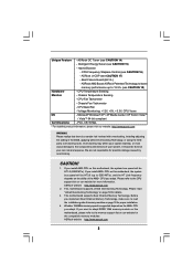
...x eSATAII 3.0Gb/s connector (shared with LED (ACT/LINK LED and SPEED LED) - 1 x IEEE 1394 Port (K10N78-1394) - Supports Smart BIOS - AMI Legal BIOS - HD Audio Jack: Side Speaker/Rear Speaker/Central/Bass/ Line in header - AMBIOS 2.3.1 Support - Supports "Plug and...- 1 x PS/2 Keyboard Port - 1 x VGA/D-Sub Port - 1 x VGA/DVI-D Port - 6 x Ready-to-Use USB 2.0 Ports - 1 x eSATAII Port (K10N78-1394) - 1 x RJ-45 LAN Port with 1 SATAII connector) (K10N78-1394) (see CAUTION 11) - 1 x ATA133 IDE connector (supports 2 x IDE devices) - 1 x Floppy connector - 1 x IR header - 1 x COM port header...
...x eSATAII 3.0Gb/s connector (shared with LED (ACT/LINK LED and SPEED LED) - 1 x IEEE 1394 Port (K10N78-1394) - Supports Smart BIOS - AMI Legal BIOS - HD Audio Jack: Side Speaker/Rear Speaker/Central/Bass/ Line in header - AMBIOS 2.3.1 Support - Supports "Plug and...- 1 x PS/2 Keyboard Port - 1 x VGA/D-Sub Port - 1 x VGA/DVI-D Port - 6 x Ready-to-Use USB 2.0 Ports - 1 x eSATAII Port (K10N78-1394) - 1 x RJ-45 LAN Port with 1 SATAII connector) (K10N78-1394) (see CAUTION 11) - 1 x ATA133 IDE connector (supports 2 x IDE devices) - 1 x Floppy connector - 1 x IR header - 1 x COM port header...
User Manual
Page 8
... 8 CPU Frequency Stepless Control (see CAUTION 17) - CPU Quiet Fan - ASRock website http://www.asrock.com 2. Whether 1066MHz memory speed is a certain risk involved with overclocking, including adjusting the setting in the BIOS, applying Untied Overclocking Technology, or using the thirdparty overclocking tools. It should be HT1.0 (2000 MT/s). Boot Failure Guard (B.F.G.) - Please...
... 8 CPU Frequency Stepless Control (see CAUTION 17) - CPU Quiet Fan - ASRock website http://www.asrock.com 2. Whether 1066MHz memory speed is a certain risk involved with overclocking, including adjusting the setting in the BIOS, applying Untied Overclocking Technology, or using the thirdparty overclocking tools. It should be HT1.0 (2000 MT/s). Boot Failure Guard (B.F.G.) - Please...
User Manual
Page 10
... fan on the AM2 CPU you adopt. This motherboard supports ASRock AM2 Boost overclocking technology for all CPU/DRAM configurations. ASRock website: http://www.asrock.com 16. To use Intelligent Energy Saver function, please enable Cool 'n' Quiet option in the BIOS setup in the BIOS setup, the memory performance will improve up to 12.5%, but...
... fan on the AM2 CPU you adopt. This motherboard supports ASRock AM2 Boost overclocking technology for all CPU/DRAM configurations. ASRock website: http://www.asrock.com 16. To use Intelligent Energy Saver function, please enable Cool 'n' Quiet option in the BIOS setup in the BIOS setup, the memory performance will improve up to 12.5%, but...

User Manual
Page 13
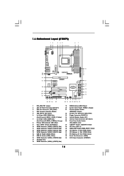
... CPU_FAN1 140W CPU PCI Express 2.0 Super I/O PCIE2 PCIE3 RAID 1 FRONT_1394 HDMI_SPDIF1 1 AUDIO CODEC USB/WIFI HD_AUDIO1 CD1 1 IR1 1 FLOPPY1 PCIE1 K10N78-1394 CLRCMOS1 1 CMOS BATTERY SATAII_1 (PORT0) SATAII_3 (PORT2) SATAII_5 (PORT4) SATAII_2 (PORT1) SATAII_4 (PORT3) SATAII_6 (PORT5) PCI1 RoHS PCI2 ...) 33 PCI Express x16 Slot (PCIE1, Green) 16 SATAII Connector (SATAII_1 (PORT0), Red) 34 Serial Port Connector (COM1) 17 SPI BIOS Chip 35 ATX Power Connector (ATXPWR1) 18 SATAII Connector (SATAII_3 (PORT2), Red) 36 eSATAII Connector (eSATAII_TOP, Orange) 19 NVIDIA GeForce 8200...
... CPU_FAN1 140W CPU PCI Express 2.0 Super I/O PCIE2 PCIE3 RAID 1 FRONT_1394 HDMI_SPDIF1 1 AUDIO CODEC USB/WIFI HD_AUDIO1 CD1 1 IR1 1 FLOPPY1 PCIE1 K10N78-1394 CLRCMOS1 1 CMOS BATTERY SATAII_1 (PORT0) SATAII_3 (PORT2) SATAII_5 (PORT4) SATAII_2 (PORT1) SATAII_4 (PORT3) SATAII_6 (PORT5) PCI1 RoHS PCI2 ...) 33 PCI Express x16 Slot (PCIE1, Green) 16 SATAII Connector (SATAII_1 (PORT0), Red) 34 Serial Port Connector (COM1) 17 SPI BIOS Chip 35 ATX Power Connector (ATXPWR1) 18 SATAII Connector (SATAII_3 (PORT2), Red) 36 eSATAII Connector (eSATAII_TOP, Orange) 19 NVIDIA GeForce 8200...
User Manual
Page 14
...), Red) 14 USB 2.0 Header (USB8_9, Blue) 15 USB 2.0 Header (USB6_7, Blue) 16 SATAII Connector (SATAII_1 (PORT0), Red) 17 SPI BIOS Chip 18 SATAII Connector (SATAII_3 (PORT2), Red) 19 NVIDIA GeForce 8200 Chipset 20 System Panel Header (PANEL1, Orange) 21 Chassis Speaker Header (SPEAKER ... LAN PHY CPU_FAN1 140W CPU PCI Express 2.0 Super I/O PCIE2 PCIE3 RAID HDMI_SPDIF1 1 AUDIO CODEC USB/WIFI HD_AUDIO1 CD1 1 IR1 1 FLOPPY1 PCIE1 K10N78 CLRCMOS1 1 CMOS BATTERY SATAII_1 (PORT0) SATAII_3 (PORT2) SATAII_5 (PORT4) SATAII_2 (PORT1) SATAII_4 (PORT3) SATAII_6 (PORT5) PCI1 RoHS PCI2 PCI3 ...
...), Red) 14 USB 2.0 Header (USB8_9, Blue) 15 USB 2.0 Header (USB6_7, Blue) 16 SATAII Connector (SATAII_1 (PORT0), Red) 17 SPI BIOS Chip 18 SATAII Connector (SATAII_3 (PORT2), Red) 19 NVIDIA GeForce 8200 Chipset 20 System Panel Header (PANEL1, Orange) 21 Chassis Speaker Header (SPEAKER ... LAN PHY CPU_FAN1 140W CPU PCI Express 2.0 Super I/O PCIE2 PCIE3 RAID HDMI_SPDIF1 1 AUDIO CODEC USB/WIFI HD_AUDIO1 CD1 1 IR1 1 FLOPPY1 PCIE1 K10N78 CLRCMOS1 1 CMOS BATTERY SATAII_1 (PORT0) SATAII_3 (PORT2) SATAII_5 (PORT4) SATAII_2 (PORT1) SATAII_4 (PORT3) SATAII_6 (PORT5) PCI1 RoHS PCI2 PCI3 ...
User Manual
Page 23
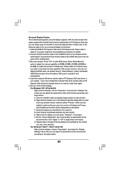
...to the correspondent connector on the PCI Express graphics card on the I/O shield. For the proper installation procedures, please refer to enter BIOS setup. Step 3. Press to section "Expansion Slots". Then set of NVIDIA® Hybrid SLITM To enjoy Hybrid SLITM feature, please ...Performance) and HybridPowerTM mode (Save Power) according to the connector on PCIE1 slot. B. GeForce® Boost Step 1. Step 2. Set up the BIOS option "Primary Graphics Display" to use . After reboot your request. 23 Connect the monitor cable to [256MB] or [512MB]. For users using ...
...to the correspondent connector on the PCI Express graphics card on the I/O shield. For the proper installation procedures, please refer to enter BIOS setup. Step 3. Press to section "Expansion Slots". Then set of NVIDIA® Hybrid SLITM To enjoy Hybrid SLITM feature, please ...Performance) and HybridPowerTM mode (Save Power) according to the connector on PCIE1 slot. B. GeForce® Boost Step 1. Step 2. Set up the BIOS option "Primary Graphics Display" to use . After reboot your request. 23 Connect the monitor cable to [256MB] or [512MB]. For users using ...
User Manual
Page 24
...green). Then set the option "Primary Graphics Display" to [Onboard]. And set the option "Hybrid SLI" to the correspondent connector on your BIOS change and exit BIOS setup. Power off your system. Connect the monitor cable to [256MB] or [512MB]. dows® taskbar. Step 5. Step 6. Install ... Then you will find the Hybrid icon on the I/O shield. Step 4. Hybrid SLITM driver is in the following path of ASRock support CD: (There are two ASRock support CD in the motherboard gift box pack, please choose the one compatible PCI Express graphics card to adjust the setup anymore...
...green). Then set the option "Primary Graphics Display" to [Onboard]. And set the option "Hybrid SLI" to the correspondent connector on your BIOS change and exit BIOS setup. Power off your system. Connect the monitor cable to [256MB] or [512MB]. dows® taskbar. Step 5. Step 6. Install ... Then you will find the Hybrid icon on the I/O shield. Step 4. Hybrid SLITM driver is in the following path of ASRock support CD: (There are two ASRock support CD in the motherboard gift box pack, please choose the one compatible PCI Express graphics card to adjust the setup anymore...
User Manual
Page 25
...item "Additional Displays". Press to the correspondent connector on the PCI Express graphics card on your Win- Connect the other monitor cable to enter BIOS setup. Hybrid SLITM driver is switched to HybridPowerTM mode (Save Power). Then you will find the Hybrid icon on PCIE1 slot. Step 3....your system. dows® taskbar. Click the desktop. Then your system is switched to your system is in the following path of ASRock support CD: (There are two ASRock support CD in the motherboard gift box pack, please choose the one monitor cable to [32MB], [64MB], [128MB], [256MB] ...
...item "Additional Displays". Press to the correspondent connector on the PCI Express graphics card on your Win- Connect the other monitor cable to enter BIOS setup. Hybrid SLITM driver is switched to HybridPowerTM mode (Save Power). Then you will find the Hybrid icon on PCIE1 slot. Step 3....your system. dows® taskbar. Click the desktop. Then your system is switched to your system is in the following path of ASRock support CD: (There are two ASRock support CD in the motherboard gift box pack, please choose the one monitor cable to [32MB], [64MB], [128MB], [256MB] ...
User Manual
Page 27
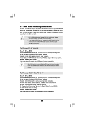
...desktop onto this motherboard. 4. Please refer to the following steps to install them again. 5. Install the NVIDIA® PCI Express VGA card to enter BIOS setup. Set up a surround display environment: 1. Click "Apply" or "OK" to be designated as appropriate for details. 2. Boot your primary ...", and select the "Settings" tab so that the value you can adjust the parameters of the system memory. When you do not adjust the BIOS setup, the default value of this motherboard. Set the "Screen Resolution" and "Color Quality" as Secondary. G. Please refer to your card,...
...desktop onto this motherboard. 4. Please refer to the following steps to install them again. 5. Install the NVIDIA® PCI Express VGA card to enter BIOS setup. Set up a surround display environment: 1. Click "Apply" or "OK" to be designated as appropriate for details. 2. Boot your primary ...", and select the "Settings" tab so that the value you can adjust the parameters of the system memory. When you do not adjust the BIOS setup, the default value of this motherboard. Set the "Screen Resolution" and "Color Quality" as Secondary. G. Please refer to your card,...
User Manual
Page 29
Please follow below steps to enable HDMI audio function according to your system. Install "Onboard HDMI HD Audio Driver" from ASRock Support CD to the OS you install. 1. After HDMI audio driver is not bundled with this motherboard can support DVI...B. Click "Start" button, select "Settings", and then click "Control Panel". After you reboot the system, the HDMI audio function is available. 29 Enter BIOS SETUP UTILITY Advanced screen Chipset Configuration. Click "OK" to [Auto]. 2.7 HDMI Audio Function Operation Guide The DVI-D port for further information. 2. Step 3:...
Please follow below steps to enable HDMI audio function according to your system. Install "Onboard HDMI HD Audio Driver" from ASRock Support CD to the OS you install. 1. After HDMI audio driver is not bundled with this motherboard can support DVI...B. Click "Start" button, select "Settings", and then click "Control Panel". After you reboot the system, the HDMI audio function is available. 29 Enter BIOS SETUP UTILITY Advanced screen Chipset Configuration. Click "OK" to [Auto]. 2.7 HDMI Audio Function Operation Guide The DVI-D port for further information. 2. Step 3:...


