
RAID Installation Guide
Page 2
... RAID This motherboard adopts a chipset that optimizes two identical hard disk drives to the entire system since it will direct all applications to the user manual for creating a RAID volume.
... RAID This motherboard adopts a chipset that optimizes two identical hard disk drives to the entire system since it will direct all applications to the user manual for creating a RAID volume.
RAID Installation Guide
Page 5
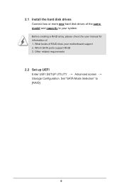
What levels of RAID does your system. Set "SATA Mode Selection" to your motherboard support 2. Before creating a RAID array, please check the user manual for information of: 1. Which SATA ports support RAID 3. 2.1 Install the hard disk drives Connect two or more new hard disk drives of the same model and capacity to [RAID]. 5 Other related requirements 2.2 Set up UEFI Enter UEFI SETUP UTILITY Advanced screen Storage Configuration.
What levels of RAID does your system. Set "SATA Mode Selection" to your motherboard support 2. Before creating a RAID array, please check the user manual for information of: 1. Which SATA ports support RAID 3. 2.1 Install the hard disk drives Connect two or more new hard disk drives of the same model and capacity to [RAID]. 5 Other related requirements 2.2 Set up UEFI Enter UEFI SETUP UTILITY Advanced screen Storage Configuration.

User Manual
Page 1
H61TM-ITX User Manual Version 1.0 Published November 2012 Copyright©2012 ASRock INC. All rights reserved. 1
H61TM-ITX User Manual Version 1.0 Published November 2012 Copyright©2012 ASRock INC. All rights reserved. 1

User Manual
Page 2
... the related regulations in any form or by the purchaser for backup purpose, without written consent of ASRock Inc. Disclaimer: Specifications and information contained in the manual or product. Operation is subject to the following two conditions: (1) this device may not cause harmful...received, including interference that may appear in Perchlorate Best Management Practices (BMP) regulations passed by ASRock. CALIFORNIA, USA ONLY The Lithium battery adopted on this manual, ASRock does not provide warranty of any means, except duplication of documentation by any kind, either ...
... the related regulations in any form or by the purchaser for backup purpose, without written consent of ASRock Inc. Disclaimer: Specifications and information contained in the manual or product. Operation is subject to the following two conditions: (1) this device may not cause harmful...received, including interference that may appear in Perchlorate Best Management Practices (BMP) regulations passed by ASRock. CALIFORNIA, USA ONLY The Lithium battery adopted on this manual, ASRock does not provide warranty of any means, except duplication of documentation by any kind, either ...
User Manual
Page 5
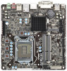
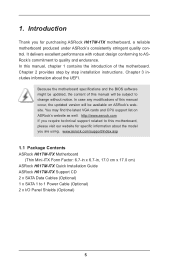
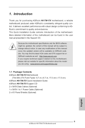
... ASRock H61TM-ITX Motherboard (Thin Mini-ITX Form Factor: 6.7-in x 6.7-in, 17.0 cm x 17.0 cm) ASRock H61TM-ITX Quick Installation Guide ASRock H61TM-ITX Support CD 2 x SATA Data Cables (Optional) 1 x SATA 1 to quality and endurance. Introduction Thank you require technical support related to change without notice. In this motherboard, please visit our website for purchasing ASRock H61TM-ITX motherboard, a reliable motherboard produced under ASRock...
... ASRock H61TM-ITX Motherboard (Thin Mini-ITX Form Factor: 6.7-in x 6.7-in, 17.0 cm x 17.0 cm) ASRock H61TM-ITX Quick Installation Guide ASRock H61TM-ITX Support CD 2 x SATA Data Cables (Optional) 1 x SATA 1 to quality and endurance. Introduction Thank you require technical support related to change without notice. In this motherboard, please visit our website for purchasing ASRock H61TM-ITX motherboard, a reliable motherboard produced under ASRock...

User Manual
Page 20
... interfere with the remaining fasteners. Align the fasteners with the fan header on the motherboard. Step 5. For proper installation, please kindly refer to the instruction manuals of a heatsink and fan for 1155-Pin CPUs. Step 1. If you need to spray thermal interface material between the CPU and the heatsink to illustrate...
... interfere with the remaining fasteners. Align the fasteners with the fan header on the motherboard. Step 5. For proper installation, please kindly refer to the instruction manuals of a heatsink and fan for 1155-Pin CPUs. Step 1. If you need to spray thermal interface material between the CPU and the heatsink to illustrate...

User Manual
Page 27
.... Then click "FrontMic". E. C. Select "Recorder". For Windows® 8 / 8 64-bit / 7 / 7 64-bit / VistaTM / VistaTM 64-bit OS: Go to the "FrontMic" Tab in our manual and chassis manual to OUT2_L. B. If you use an AC'97 audio panel, please install it to MIC2_L. Connect Mic_IN (MIC) to the front panel audio header...
.... Then click "FrontMic". E. C. Select "Recorder". For Windows® 8 / 8 64-bit / 7 / 7 64-bit / VistaTM / VistaTM 64-bit OS: Go to the "FrontMic" Tab in our manual and chassis manual to OUT2_L. B. If you use an AC'97 audio panel, please install it to MIC2_L. Connect Mic_IN (MIC) to the front panel audio header...

User Manual
Page 37
HDDs that the required SATA drivers are indicated in the product spec on our support website: www.asrock.com 6. The support information of our motherboards are installed properly. Points for our motherboard which supports Hot Plug. * Hot Plug might not be supported by ...step to use the SATA power cable & data cable from your dealer or HDD user manual. Make sure to reduce the risk of its limitations. Without the SATA 15-pin power connector interface, Hot Plug cannot be damaged. 5. Even though some...
HDDs that the required SATA drivers are indicated in the product spec on our support website: www.asrock.com 6. The support information of our motherboards are installed properly. Points for our motherboard which supports Hot Plug. * Hot Plug might not be supported by ...step to use the SATA power cable & data cable from your dealer or HDD user manual. Make sure to reduce the risk of its limitations. Without the SATA 15-pin power connector interface, Hot Plug cannot be damaged. 5. Even though some...

User Manual
Page 44
DRAM Configuration DRAM tCL Use this to load XMP settings. DRAM Timing Configuration Load XMP Setting Use this to change CAS# Latency (tCL) Auto/Manual settings. Use this to configure the maximum instantaneous current allowed for the secondary plane. Primary Plane Current Limit Use this to configure short duration power ...
DRAM Configuration DRAM tCL Use this to load XMP settings. DRAM Timing Configuration Load XMP Setting Use this to change CAS# Latency (tCL) Auto/Manual settings. Use this to configure the maximum instantaneous current allowed for the secondary plane. Primary Plane Current Limit Use this to configure short duration power ...

User Manual
Page 45
... default is [Auto]. DRAM tRTP Use this to change Read to change Command Rate (CR) Auto/Manual settings. The default is [Auto]. ODT WR (CHA) Use this to change CAS# Write Latency (tCWL) Auto/Manual settings. The default is [Auto]. The default is [Auto]. The default is [Auto]. The default... is [Auto]. The default is [Auto]. DRAM tCWL Use this to change ODT (CHA) Auto/Manual settings. The default is [Auto]. The default is 45 DRAM tWTR Use this to change Write to change Four Activate Window (tFAW) Auto...
... default is [Auto]. DRAM tRTP Use this to change Read to change Command Rate (CR) Auto/Manual settings. The default is [Auto]. ODT WR (CHA) Use this to change CAS# Write Latency (tCWL) Auto/Manual settings. The default is [Auto]. The default is [Auto]. The default is [Auto]. The default... is [Auto]. The default is [Auto]. DRAM tCWL Use this to change ODT (CHA) Auto/Manual settings. The default is [Auto]. The default is 45 DRAM tWTR Use this to change Write to change Four Activate Window (tFAW) Auto...

User Manual
Page 46
...The default is [Auto]. The default value is [Enabled]. The default value is [Auto]. ODT WR (CHB) Use this to change ODT (CHB) Auto/Manual settings. The default is [Auto]. 46 The default is [Auto]. MRC Fast Boot Use this to configure DRAM Voltage. ODT NOM (CHA) Use this to... change ODT (CHA) Auto/Manual settings. The default is [Auto]. The default value is [Auto]. Voltage Configuration DRAM Voltage Use this to configure VTT Voltage. VTT Voltage Use this to...
...The default is [Auto]. The default value is [Enabled]. The default value is [Auto]. ODT WR (CHB) Use this to change ODT (CHB) Auto/Manual settings. The default is [Auto]. 46 The default is [Auto]. MRC Fast Boot Use this to configure DRAM Voltage. ODT NOM (CHA) Use this to... change ODT (CHA) Auto/Manual settings. The default is [Auto]. The default value is [Auto]. Voltage Configuration DRAM Voltage Use this to configure VTT Voltage. VTT Voltage Use this to...
Quick Installation Guide
Page 5
... well. It delivers excellent performance with robust design conforming to ASRock's commitment to 1 Power Cable (Optional) 2 x I/O Panel Shields (Optional) 5 ASRock H61TM-ITX Motherboard English In case any modifications of this manual will be found in the user manual presented in , 17.0 cm x 17.0 cm) ASRock H61TM-ITX Quick Installation Guide ASRock H61TM-ITX Support CD 2 x SATA Data Cables (Optional) 1 x SATA 1 to quality...
... well. It delivers excellent performance with robust design conforming to ASRock's commitment to 1 Power Cable (Optional) 2 x I/O Panel Shields (Optional) 5 ASRock H61TM-ITX Motherboard English In case any modifications of this manual will be found in the user manual presented in , 17.0 cm x 17.0 cm) ASRock H61TM-ITX Quick Installation Guide ASRock H61TM-ITX Support CD 2 x SATA Data Cables (Optional) 1 x SATA 1 to quality...
Quick Installation Guide
Page 12
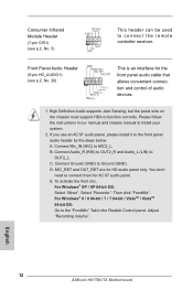
... audio header by the steps below: A. You don't need to install your system. 2. Then click "FrontMic". Please follow the instructions in our manual and chassis manual to connect them for AC'97 audio panel. Connect Audio_R (RIN) to OUT2_R and Audio_L (LIN) to MIC2_L. C. For Windows® XP... HDA to the "FrontMic" Tab in LED 1 +5VA NC GND This header can be used to connect the remote controller receiver. English 12 ASRock H61TM-ITX Motherboard E. Consumer Infrared Module Header (7-pin CIR1) (see p.2, No. 26) This is an interface for the front panel audio cable that allows...
... audio header by the steps below: A. You don't need to install your system. 2. Then click "FrontMic". Please follow the instructions in our manual and chassis manual to connect them for AC'97 audio panel. Connect Audio_R (RIN) to OUT2_R and Audio_L (LIN) to MIC2_L. C. For Windows® XP... HDA to the "FrontMic" Tab in LED 1 +5VA NC GND This header can be used to connect the remote controller receiver. English 12 ASRock H61TM-ITX Motherboard E. Consumer Infrared Module Header (7-pin CIR1) (see p.2, No. 26) This is an interface for the front panel audio cable that allows...
Quick Installation Guide
Page 17
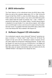
...be user-friendly. If you start up the computer, please press or during the Power-On-Self-Test (POST) to display the menu. 17 ASRock H61TM-ITX Motherboard English To begin using the Support CD, insert the CD into your computer. 2. BIOS Information The Flash Memory on the system chassis. ...the system by pressing + + , or pressing the reset button on the motherboard stores the BIOS Setup Utility. When you wish to the User Manual (PDF file) contained in the Support CD to enter the BIOS Setup utility; If the Main Menu does not appear automatically, locate and double-...
...be user-friendly. If you start up the computer, please press or during the Power-On-Self-Test (POST) to display the menu. 17 ASRock H61TM-ITX Motherboard English To begin using the Support CD, insert the CD into your computer. 2. BIOS Information The Flash Memory on the system chassis. ...the system by pressing + + , or pressing the reset button on the motherboard stores the BIOS Setup Utility. When you wish to the User Manual (PDF file) contained in the Support CD to enter the BIOS Setup utility; If the Main Menu does not appear automatically, locate and double-...
