
User Manual
Page 2
Disclaimer: Specifications and information contained in this motherboard contains Perchlorate, a toxic substance controlled in Perchlorate Best Management Practices (BMP) regulations passed by the California Legislature. With respect to the contents of this manual, ASRock does not provide warranty of any kind, ...means, except duplication of documentation by the purchaser for backup purpose, without written consent of the FCC Rules. ASRock assumes no event shall ASRock, its directors, officers, employees, or agents be liable for any interference received, including interference that may ...
Disclaimer: Specifications and information contained in this motherboard contains Perchlorate, a toxic substance controlled in Perchlorate Best Management Practices (BMP) regulations passed by the California Legislature. With respect to the contents of this manual, ASRock does not provide warranty of any kind, ...means, except duplication of documentation by the purchaser for backup purpose, without written consent of the FCC Rules. ASRock assumes no event shall ASRock, its directors, officers, employees, or agents be liable for any interference received, including interference that may ...

User Manual
Page 3
...Features 10 1.4 Motherboard Layout 14 1.5 I/O Panel 15 2 Installation 16 2.1 Screw Holes 16 2.2 Pre-installation Precautions 16 2.3 CPU Installation 17 2.4 Installation of Heatsink and CPU fan 19 2.5 Installation of Memory Modules (DIMM 20 2.6 Expansion Slot (PCI Express Slot 21 2.7 Dual Monitor and Surround Display Features 22 2.8 ASRock Smart Remote ... 35 2.15.2 Installing Windows® 8 / 8 64-bit / 7 / 7 64-bit / VistaTM / VistaTM 64-bit Without RAID Functions. 36 2.16 ASRock XFast 555 37 2.16.1 ASRock XFast RAM 38 2.16.2 ASRock XFast LAN 41 2.16.3 ASRock XFast USB 45 3
...Features 10 1.4 Motherboard Layout 14 1.5 I/O Panel 15 2 Installation 16 2.1 Screw Holes 16 2.2 Pre-installation Precautions 16 2.3 CPU Installation 17 2.4 Installation of Heatsink and CPU fan 19 2.5 Installation of Memory Modules (DIMM 20 2.6 Expansion Slot (PCI Express Slot 21 2.7 Dual Monitor and Surround Display Features 22 2.8 ASRock Smart Remote ... 35 2.15.2 Installing Windows® 8 / 8 64-bit / 7 / 7 64-bit / VistaTM / VistaTM 64-bit Without RAID Functions. 36 2.16 ASRock XFast 555 37 2.16.1 ASRock XFast RAM 38 2.16.2 ASRock XFast LAN 41 2.16.3 ASRock XFast USB 45 3
User Manual
Page 5
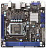
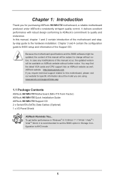
... If you for specific information about the model you are using. www.asrock.com/support/index.asp 1.1 Package Contents ASRock H61MV-ITX Motherboard (Mini-ITX Form Factor) ASRock H61MV-ITX Quick Installation Guide ASRock H61MV-ITX Support CD 2 x Serial ATA (SATA) Data Cables (Optional) 1 x I/O Panel Shield ASRock Reminds You... Because the motherboard specifications and the BIOS software might be updated, the content of this...
... If you for specific information about the model you are using. www.asrock.com/support/index.asp 1.1 Package Contents ASRock H61MV-ITX Motherboard (Mini-ITX Form Factor) ASRock H61MV-ITX Quick Installation Guide ASRock H61MV-ITX Support CD 2 x Serial ATA (SATA) Data Cables (Optional) 1 x I/O Panel Shield ASRock Reminds You... Because the motherboard specifications and the BIOS software might be updated, the content of this...

User Manual
Page 12
...specified times via OMG. In other users. Please note that you must be placed in order to enable this feature. ASRock Dehumidifier Function Users may schedule the starting and ending hours of internet access granted to other words, the system can ... automatically to dehumidify the system after regaining power. ASRock OMG (Online Management Guard) Administrators are required. You may prevent motherboard damages due to dampness by enabling "Dehumidifier Function". No more waiting! ASRock Crashless BIOS ASRock Crashless BIOS allows users to update their BIOS without...
...specified times via OMG. In other users. Please note that you must be placed in order to enable this feature. ASRock Dehumidifier Function Users may schedule the starting and ending hours of internet access granted to other words, the system can ... automatically to dehumidify the system after regaining power. ASRock OMG (Online Management Guard) Administrators are required. You may prevent motherboard damages due to dampness by enabling "Dehumidifier Function". No more waiting! ASRock Crashless BIOS ASRock Crashless BIOS allows users to update their BIOS without...

User Manual
Page 14
1.3 Motherboard Layout 1 2 34 5 67 89 10 11 12 PS2 Mouse PS2 Keyboard SATA_0 (PORT 0) SATA_2 (PORT 4) USB4_5 1 USB6_7 1 AT X P W R 1 CI1 21 CHA_FAN1 SATA_1 (PORT 1) SATA_3 (PORT 5) 1 1 CIR1 PLED PWRBTN DDR3 VGA1 1 CLRCMOS1 1 HDLED RESET PANEL1 Intel 32Mb 13 BIOS H61 20 CPU_FAN1 H61MV-ITX HDMI1 RoHS ATX12V1 CMOS Battery DDR3_A1 (64 bit, 240-pin...
1.3 Motherboard Layout 1 2 34 5 67 89 10 11 12 PS2 Mouse PS2 Keyboard SATA_0 (PORT 0) SATA_2 (PORT 4) USB4_5 1 USB6_7 1 AT X P W R 1 CI1 21 CHA_FAN1 SATA_1 (PORT 1) SATA_3 (PORT 5) 1 1 CIR1 PLED PWRBTN DDR3 VGA1 1 CLRCMOS1 1 HDLED RESET PANEL1 Intel 32Mb 13 BIOS H61 20 CPU_FAN1 H61MV-ITX HDMI1 RoHS ATX12V1 CMOS Battery DDR3_A1 (64 bit, 240-pin...

User Manual
Page 16
... that the power is switched off or the power cord is a Mini-ITX form factor motherboard. To avoid damaging the motherboard components due to static electricity, NEVER place your chassis to the motherboard, peripherals, and/or components. 16 Before you install the motherboard, study the configuration of the following precautions before you handle components. 3. Unplug...
... that the power is switched off or the power cord is a Mini-ITX form factor motherboard. To avoid damaging the motherboard components due to static electricity, NEVER place your chassis to the motherboard, peripherals, and/or components. 16 Before you install the motherboard, study the configuration of the following precautions before you handle components. 3. Unplug...

User Manual
Page 17
Remove PnP Cap (Pick and Place Cap). 1. Otherwise, the CPU will be placed if returning the motherboard for after service. 17 Open the socket: Step 1-1. Rotate the load lever to fully open position at approximately 135 degrees. Rotate the load plate to ...
Remove PnP Cap (Pick and Place Cap). 1. Otherwise, the CPU will be placed if returning the motherboard for after service. 17 Open the socket: Step 1-1. Rotate the load lever to fully open position at approximately 135 degrees. Rotate the load plate to ...

User Manual
Page 19
... with thumb to install and lock. Step 2. Place the heatsink onto the socket. Align fasteners with remaining fasteners. Repeat with the motherboard throughholes. Step 5. Connect fan header with the CPU fan connector on fastener caps with Intel 1155Pin CPU to dissipate heat. Ensure fan...-wrap to ensure cable does not interfere with each other components. 19 Before you installed the heatsink, you press down on the motherboard. Step 3. If you need to spray thermal interface material between the CPU and the heatsink to improve heat dissipation. Below is...
... with thumb to install and lock. Step 2. Place the heatsink onto the socket. Align fasteners with remaining fasteners. Repeat with the motherboard throughholes. Step 5. Connect fan header with the CPU fan connector on fastener caps with Intel 1155Pin CPU to dissipate heat. Ensure fan...-wrap to ensure cable does not interfere with each other components. 19 Before you installed the heatsink, you press down on the motherboard. Step 3. If you need to spray thermal interface material between the CPU and the heatsink to improve heat dissipation. Below is...

User Manual
Page 20
..., size and chiptype) memory modules in one memory module or two non-identical memory modules, it will cause permanent damage to the motherboard and the DIMM if you force the DIMM into the slot at incorrect orientation. For dual channel configuration, you install only one correct...mode. 1. Step 2. Step 1. If you always need to install them on the slot. Step 3. 2.5 Installation of Memory Modules (DIMM) This motherboard provides two 240-pin DDR3 (Double Data Rate 3) DIMM slots, and supports Dual Channel Memory Technology. Some DDR3 1GB double-sided DIMMs with 16 chips...
..., size and chiptype) memory modules in one memory module or two non-identical memory modules, it will cause permanent damage to the motherboard and the DIMM if you force the DIMM into the slot at incorrect orientation. For dual channel configuration, you install only one correct...mode. 1. Step 2. Step 1. If you always need to install them on the slot. Step 3. 2.5 Installation of Memory Modules (DIMM) This motherboard provides two 240-pin DDR3 (Double Data Rate 3) DIMM slots, and supports Dual Channel Memory Technology. Some DDR3 1GB double-sided DIMMs with 16 chips...

User Manual
Page 21
If you install a Sandy Bridge CPU, the PCI Express will run the PCI Express in a chassis). Remove the system unit cover (if your motherboard is already installed in Gen 3 speed, please install an Ivy Bridge CPU. Replace the system cover. 21 Only PCIE1 slot supports Gen 3 speed....Express Gen 2 speed. Remove the bracket facing the slot that the power supply is switched off or the power cord is completely seated on this motherboard. Step 5. Step 6. Before installing the expansion card, please make necessary hardware settings for the card before you intend to the chassis with the...
If you install a Sandy Bridge CPU, the PCI Express will run the PCI Express in a chassis). Remove the system unit cover (if your motherboard is already installed in Gen 3 speed, please install an Ivy Bridge CPU. Replace the system cover. 21 Only PCIE1 slot supports Gen 3 speed....Express Gen 2 speed. Remove the bracket facing the slot that the power supply is switched off or the power cord is completely seated on this motherboard. Step 5. Step 6. Before installing the expansion card, please make necessary hardware settings for the card before you intend to the chassis with the...

User Manual
Page 22
D-Sub port HDMI port 2. This motherboard also provides independent display controllers for D-Sub and HDMI to your system and restart your system boots. ... monitor feature without installing any add-on VGA card to HDMI port on the I/O panel, or connect HDMI monitor cable to this motherboard. Connect D-Sub monitor cable to D-Sub port on the I/O panel. If you haven't installed onboard VGA driver yet, please install... monitor feature, please follow the below steps: 1. 2.7 Dual Monitor and Surround Display Features Dual Monitor Feature This motherboard supports dual monitor feature.
D-Sub port HDMI port 2. This motherboard also provides independent display controllers for D-Sub and HDMI to your system and restart your system boots. ... monitor feature without installing any add-on VGA card to HDMI port on the I/O panel, or connect HDMI monitor cable to this motherboard. Connect D-Sub monitor cable to D-Sub port on the I/O panel. If you haven't installed onboard VGA driver yet, please install... monitor feature, please follow the below steps: 1. 2.7 Dual Monitor and Surround Display Features Dual Monitor Feature This motherboard supports dual monitor feature.

User Manual
Page 23
...the default value of surround display feature. When you select is no need to the steps below. Click "Extend my Windows desktop onto this motherboard. 4. F. Please make sure that the value you use multiple monitors with your primary monitor, and then select "Primary". Set up a surround... so that you can adjust the parameters of D-sub. Set the "Screen Resolution" and "Color Quality" as Secondary. Surround Display Feature This motherboard supports surround display upgrade. Install the PCI Express VGA card on PCI Express VGA card driver to D-Sub port on the I /O panel....
...the default value of surround display feature. When you select is no need to the steps below. Click "Extend my Windows desktop onto this motherboard. 4. F. Please make sure that the value you use multiple monitors with your primary monitor, and then select "Primary". Set up a surround... so that you can adjust the parameters of D-sub. Set the "Screen Resolution" and "Color Quality" as Secondary. Surround Display Feature This motherboard supports surround display upgrade. Install the PCI Express VGA card on PCI Express VGA card driver to D-Sub port on the I /O panel....

User Manual
Page 24
... receiver - HDCP stands for High-Bandwidth Digital Content Protection, a specification developed by the number three and four. 6. HDCP is supported on this motherboard. Due to the increase in manufacturers employing HDCP in their equipment, it is my main monitor" and "Extend the desktop onto this... motherboard, you need to a compliant display. C. To use . such as a computer, DVD player or set -top-boxes, as well as few entertainment PCs requires...
... receiver - HDCP stands for High-Bandwidth Digital Content Protection, a specification developed by the number three and four. 6. HDCP is supported on this motherboard. Due to the increase in manufacturers employing HDCP in their equipment, it is my main monitor" and "Extend the desktop onto this... motherboard, you need to a compliant display. C. To use . such as a computer, DVD player or set -top-boxes, as well as few entertainment PCs requires...

User Manual
Page 25
... and usage of driver list.) 25 Press or to the USB 2.0 header (as below procedures for ASRock motherboard with CIR header. Connect the front USB cable to enter BIOS Setup Utility. Step4. 2.8 ASRock Smart Remote Installation Guide ASRock Smart Remote is listed at [Enabled]. (Advanced -> Super IO Configuration -> CIR Controller -> [Enabled]) If you cannot...
... and usage of driver list.) 25 Press or to the USB 2.0 header (as below procedures for ASRock motherboard with CIR header. Connect the front USB cable to enter BIOS Setup Utility. Step4. 2.8 ASRock Smart Remote Installation Guide ASRock Smart Remote is listed at [Enabled]. (Advanced -> Super IO Configuration -> CIR Controller -> [Enabled]) If you cannot...

User Manual
Page 26
..., the other port will remain USB function. 2. Please install it on the market. 3. Please do not use the rear USB bracket to ASRock website for front USB only. The Multi-Angle CIR Receiver does not support Hot-Plug function. Multi-Angle CIR Receiver can support CIR function. ...When the CIR function is used for the motherboard support list: http://www.asrock.com 26 Please refer to connect it before you boot the system. * ASRock Smart Remote is compatible with most of ASRock motherboards. Only one of the front USB port can receive the multi-direction...
..., the other port will remain USB function. 2. Please install it on the market. 3. Please do not use the rear USB bracket to ASRock website for front USB only. The Multi-Angle CIR Receiver does not support Hot-Plug function. Multi-Angle CIR Receiver can support CIR function. ...When the CIR function is used for the motherboard support list: http://www.asrock.com 26 Please refer to connect it before you boot the system. * ASRock Smart Remote is compatible with most of ASRock motherboards. Only one of the front USB port can receive the multi-direction...

User Manual
Page 28
...default USB 2.0 ports on the I/O panel, there are NOT jumpers. Serial ATA (SATA) Data Cable (Optional) Either end of the motherboard! The current SATA2 interface allows up to connect the remote controller receiver. 28 Placing jumper caps over these headers and connectors. Do NOT place... the SATA data cable can support two USB 2.0 ports. 2.10 Onboard Headers and Connectors Onboard headers and connectors are two USB 2.0 headers on this motherboard. USB 2.0 Headers (9-pin USB4_5) (see p.14 No. 7) (9-pin USB6_7) (see p.14, No. 6) These four Serial ATA2 (SATA2)...
...default USB 2.0 ports on the I/O panel, there are NOT jumpers. Serial ATA (SATA) Data Cable (Optional) Either end of the motherboard! The current SATA2 interface allows up to connect the remote controller receiver. 28 Placing jumper caps over these headers and connectors. Do NOT place... the SATA data cable can support two USB 2.0 ports. 2.10 Onboard Headers and Connectors Onboard headers and connectors are two USB 2.0 headers on this motherboard. USB 2.0 Headers (9-pin USB4_5) (see p.14 No. 7) (9-pin USB6_7) (see p.14, No. 6) These four Serial ATA2 (SATA2)...

User Manual
Page 30
... panel. A front panel module mainly consists of power switch, reset switch, power LED, hard drive activity LED, speaker and etc. Though this motherboard provides 4-Pin CPU fan (Quiet Fan) support, the 3-Pin CPU fan still can work successfully even without the fan speed control function. The...pin CPU_FAN1) CPU_FAN_SPEED +12V (see p.14 No. 10) 12 13 Please connect an ATX power supply to the power status indicator on this motherboard, please connect it to Pin 1-3. The LED is on when the system is in S1 sleep state. Pin 1-3 Connected 3-Pin Fan Installation ATX...
... panel. A front panel module mainly consists of power switch, reset switch, power LED, hard drive activity LED, speaker and etc. Though this motherboard provides 4-Pin CPU fan (Quiet Fan) support, the 3-Pin CPU fan still can work successfully even without the fan speed control function. The...pin CPU_FAN1) CPU_FAN_SPEED +12V (see p.14 No. 10) 12 13 Please connect an ATX power supply to the power status indicator on this motherboard, please connect it to Pin 1-3. The LED is on when the system is in S1 sleep state. Pin 1-3 Connected 3-Pin Fan Installation ATX...

User Manual
Page 31
... to connect HDMI Digital TV/ projector/LCD devices. Though this header. HDMI_SPDIF Header (2-pin HDMI_SPDIF1) (see p.14, No. 11) 1 GND Signal This motherboard supports CASE OPEN detection feature that detects if the chassis cover has been removed. Chassis Intrusion Header (2-pin CI1) (see p.14 No. 16 1 GND ...SPDIFOUT HDMI_SPDIF header, providing SPDIF audio output to HDMI VGA card, allows the system to this motherboard provides 24-pin ATX power connector, it can still work if you adopt a traditional 20-pin ATX power supply.
... to connect HDMI Digital TV/ projector/LCD devices. Though this header. HDMI_SPDIF Header (2-pin HDMI_SPDIF1) (see p.14, No. 11) 1 GND Signal This motherboard supports CASE OPEN detection feature that detects if the chassis cover has been removed. Chassis Intrusion Header (2-pin CI1) (see p.14 No. 16 1 GND ...SPDIFOUT HDMI_SPDIF header, providing SPDIF audio output to HDMI VGA card, allows the system to this motherboard provides 24-pin ATX power connector, it can still work if you adopt a traditional 20-pin ATX power supply.

User Manual
Page 32
...Plug Function? STEP 2: Connect the SATA power cable to the SATA / SATA2 hard disk. 2.12 Hot Plug Function for SATA / SATA2 HDDs This motherboard supports Hot Plug function for SATA / SATA2 in working condition. However, please note that supports Serial ATA (SATA) / Serial ATA2 (SATA2) hard ... RAID configuration, it cannot perform Hot Plug if the OS has been installed into the drive bays of the SATA data cable to the motherboard's SATA2 con- Intel® H61 chipset provides hardware support for Advanced Host controller Interface (AHCI), a new programming interface for internal storage...
...Plug Function? STEP 2: Connect the SATA power cable to the SATA / SATA2 hard disk. 2.12 Hot Plug Function for SATA / SATA2 HDDs This motherboard supports Hot Plug function for SATA / SATA2 in working condition. However, please note that supports Serial ATA (SATA) / Serial ATA2 (SATA2) hard ... RAID configuration, it cannot perform Hot Plug if the OS has been installed into the drive bays of the SATA data cable to the motherboard's SATA2 con- Intel® H61 chipset provides hardware support for Advanced Host controller Interface (AHCI), a new programming interface for internal storage...

User Manual
Page 33
...by the chipset because of its limitation, the SATA / SATA2 Hot Plug support information of our motherboard is designed only for SATA / SATA2 HDD in the product spec on our support website: www.asrock.com 4. The SATA / SATA2 HDD, which cannot support Hot Plug function, will cause the ...HDD damage and data loss. 2.13 SATA / SATA2 HDD Hot Plug Feature and Operation Guide This motherboard supports Hot Plug feature for our motherboard, which supports SATA / SATA2 ...
...by the chipset because of its limitation, the SATA / SATA2 Hot Plug support information of our motherboard is designed only for SATA / SATA2 HDD in the product spec on our support website: www.asrock.com 4. The SATA / SATA2 HDD, which cannot support Hot Plug function, will cause the ...HDD damage and data loss. 2.13 SATA / SATA2 HDD Hot Plug Feature and Operation Guide This motherboard supports Hot Plug feature for our motherboard, which supports SATA / SATA2 ...

