
User Manual
Page 2
...in advance. When you discard the Lithium battery in California, USA, please follow the related regulations in this manual. ASRock assumes no event shall ASRock, its directors, officers, employees, or agents be reproduced, transcribed, transmitted, or translated in any language, in ...Perchlorate Best Management Practices (BMP) regulations passed by ASRock. CALIFORNIA, USA ONLY The Lithium battery adopted on this motherboard contains Perchlorate, a toxic substance controlled in any form or by any means, except duplication of ...
...in advance. When you discard the Lithium battery in California, USA, please follow the related regulations in this manual. ASRock assumes no event shall ASRock, its directors, officers, employees, or agents be reproduced, transcribed, transmitted, or translated in any language, in ...Perchlorate Best Management Practices (BMP) regulations passed by ASRock. CALIFORNIA, USA ONLY The Lithium battery adopted on this motherboard contains Perchlorate, a toxic substance controlled in any form or by any means, except duplication of ...

User Manual
Page 3
Contents 1 Introduction 5 1.1 Package Contents 5 1.2 Specifications 6 1.3 Unique Features 9 1.4 Motherboard Layout (H61M-VG3 / H61M-VS3 13 1.5 I/O Panel (H61M-VG3 14 1.6 I/O Panel (H61M-VS3 15 2 Installation 16 2.1 Screw Holes 16 2.2 Pre-installation Precautions 16 2.3 CPU Installation 17 2.4 Installation of Heatsink and CPU fan 19 2.5... RAID Functions 32 2.14.2 Installing Windows® 8 / 8 64-bit / 7 / 7 64-bit / VistaTM / VistaTM 64-bit Without RAID Functions. 33 2.15 ASRock XFast 555 34 2.15.1 ASRock XFast RAM 35 2.15.2 ASRock XFast LAN 38 2.15.3 ASRock XFast USB 42 3
Contents 1 Introduction 5 1.1 Package Contents 5 1.2 Specifications 6 1.3 Unique Features 9 1.4 Motherboard Layout (H61M-VG3 / H61M-VS3 13 1.5 I/O Panel (H61M-VG3 14 1.6 I/O Panel (H61M-VS3 15 2 Installation 16 2.1 Screw Holes 16 2.2 Pre-installation Precautions 16 2.3 CPU Installation 17 2.4 Installation of Heatsink and CPU fan 19 2.5... RAID Functions 32 2.14.2 Installing Windows® 8 / 8 64-bit / 7 / 7 64-bit / VistaTM / VistaTM 64-bit Without RAID Functions. 33 2.15 ASRock XFast 555 34 2.15.1 ASRock XFast RAM 35 2.15.2 ASRock XFast LAN 38 2.15.3 ASRock XFast USB 42 3
User Manual
Page 5
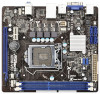
... visit our website for purchasing ASRock H61M-VG3 / H61M-VS3 motherboard, a reliable motherboard produced under ASRock's consistently stringent quality control. You may find the latest VGA cards and CPU support lists on ASRock website without notice. www.asrock.com/support/index.asp 1.1 Package Contents ASRock H61M-VG3 / H61M-VS3 Motherboard (Micro ATX Form Factor) ASRock H61M-VG3 / H61M-VS3 Quick Installation Guide ASRock H61M-VG3 / H61M-VS3 Support CD 2 x Serial ATA (SATA...
... visit our website for purchasing ASRock H61M-VG3 / H61M-VS3 motherboard, a reliable motherboard produced under ASRock's consistently stringent quality control. You may find the latest VGA cards and CPU support lists on ASRock website without notice. www.asrock.com/support/index.asp 1.1 Package Contents ASRock H61M-VG3 / H61M-VS3 Motherboard (Micro ATX Form Factor) ASRock H61M-VG3 / H61M-VS3 Quick Installation Guide ASRock H61M-VG3 / H61M-VS3 Support CD 2 x Serial ATA (SATA...

User Manual
Page 11
You may prevent motherboard damages due to dampness by enabling "Dehumidifier Function". Please note that BIOS files need to be running on automatically to dehumidify the system after regaining power. ASRock Dehumidifier Function Users may schedule the starting and ending hours of failing. When ... configured computer in the root directory of your user experience and behavior. 11 Only USB2.0 ports support this function. ASRock Crashless BIOS ASRock Crashless BIOS allows users to update their BIOS without permission to modify the system time are able to establish an internet...
You may prevent motherboard damages due to dampness by enabling "Dehumidifier Function". Please note that BIOS files need to be running on automatically to dehumidify the system after regaining power. ASRock Dehumidifier Function Users may schedule the starting and ending hours of failing. When ... configured computer in the root directory of your user experience and behavior. 11 Only USB2.0 ports support this function. ASRock Crashless BIOS ASRock Crashless BIOS allows users to update their BIOS without permission to modify the system time are able to establish an internet...

User Manual
Page 13
1.3 Motherboard Layout (H61M-VG3 / H61M-VS3) 12 3 4 5 67 8 9 DDR3 Fast RAM X DDR3_A1 (64 bit, 240-pin module) DDR3_B1 (64 bit, 240-pin module) SATA_0 (PORT 0) SATA_2 (PORT 4) PS2 Mouse PS2 Keyboard ...
1.3 Motherboard Layout (H61M-VG3 / H61M-VS3) 12 3 4 5 67 8 9 DDR3 Fast RAM X DDR3_A1 (64 bit, 240-pin module) DDR3_B1 (64 bit, 240-pin module) SATA_0 (PORT 0) SATA_2 (PORT 4) PS2 Mouse PS2 Keyboard ...

User Manual
Page 16
... carpet or the like. Do not over-tighten the screws! Before you install or remove any component. 2. Before you install the motherboard, study the configuration of the following precautions before you and damages to use a grounded wrist strap or touch a safety grounded object ...the bag that comes with the component. Make sure to the chassis. Hold components by circles to secure the motherboard to unplug the power cord before you uninstall any motherboard settings. 1. Whenever you handle components. 3. Unplug the power cord from the power supply. Chapter 2: Installation...
... carpet or the like. Do not over-tighten the screws! Before you install or remove any component. 2. Before you install the motherboard, study the configuration of the following precautions before you and damages to use a grounded wrist strap or touch a safety grounded object ...the bag that comes with the component. Make sure to the chassis. Hold components by circles to secure the motherboard to unplug the power cord before you uninstall any motherboard settings. 1. Whenever you handle components. 3. Unplug the power cord from the power supply. Chapter 2: Installation...

User Manual
Page 17
Otherwise, the CPU will be placed if returning the motherboard for after service. 17 Step 1-2. Rotate the load lever to clear retention tab. Disengaging the lever by depressing down and out on the socket. Rotate ...
Otherwise, the CPU will be placed if returning the motherboard for after service. 17 Step 1-2. Rotate the load lever to clear retention tab. Disengaging the lever by depressing down and out on the socket. Rotate ...

User Manual
Page 19
...Pin socket that the CPU and the heatsink are oriented on side closest to the CPU fan connector on the motherboard. 2.4 Installation of CPU Fan and Heatsink This motherboard is an example to illustrate the installation of the heatsink for 1155-Pin CPU. Before you installed the heatsink.... Connect fan header with fan operation or contact other . Secure excess cable with tie-wrap to the instruction manuals of IHS on the motherboard. Step 1. For proper installation, please kindly refer to ensure cable does not interfere with the CPU fan connector on the socket surface....
...Pin socket that the CPU and the heatsink are oriented on side closest to the CPU fan connector on the motherboard. 2.4 Installation of CPU Fan and Heatsink This motherboard is an example to illustrate the installation of the heatsink for 1155-Pin CPU. Before you installed the heatsink.... Connect fan header with fan operation or contact other . Secure excess cable with tie-wrap to the instruction manuals of IHS on the motherboard. Step 1. For proper installation, please kindly refer to ensure cable does not interfere with the CPU fan connector on the socket surface....
User Manual
Page 20
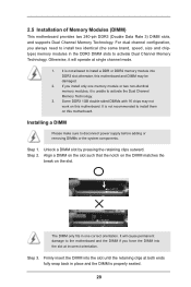
... in one memory module or two non-identical memory modules, it will cause permanent damage to install them on this motherboard. 2.5 Installation of Memory Modules (DIMM) This motherboard provides two 240-pin DDR3 (Double Data Rate 3) DIMM slots, and supports Dual Channel Memory Technology. For dual ...slot by pressing the retaining clips outward. Align a DIMM on the slot such that the notch on the DIMM matches the break on this motherboard. Firmly insert the DIMM into the slot until the retaining clips at incorrect orientation. Installing a DIMM Please make sure to install a DDR...
... in one memory module or two non-identical memory modules, it will cause permanent damage to install them on this motherboard. 2.5 Installation of Memory Modules (DIMM) This motherboard provides two 240-pin DDR3 (Double Data Rate 3) DIMM slots, and supports Dual Channel Memory Technology. For dual ...slot by pressing the retaining clips outward. Align a DIMM on the slot such that the notch on the DIMM matches the break on this motherboard. Firmly insert the DIMM into the slot until the retaining clips at incorrect orientation. Installing a DIMM Please make sure to install a DDR...

User Manual
Page 21
... expansion card Step 1. Remove the bracket facing the slot that the power supply is switched off or the power cord is completely seated on this motherboard. Step 5. Replace the system cover. 21 PCIE slots: PCIE1 (PCIE 2.0 x1 slot) is used for the card before you install a Sandy ... to the chassis with x1 lane width cards, such as Gigabit LAN card, SATA2 card, etc. Remove the system unit cover (if your motherboard is used for later use . Before installing the expansion card, please make necessary hardware settings for PCI Express x16 lane width graphics cards. Step...
... expansion card Step 1. Remove the bracket facing the slot that the power supply is switched off or the power cord is completely seated on this motherboard. Step 5. Replace the system cover. 21 PCIE slots: PCIE1 (PCIE 2.0 x1 slot) is used for the card before you install a Sandy ... to the chassis with x1 lane width cards, such as Gigabit LAN card, SATA2 card, etc. Remove the system unit cover (if your motherboard is used for later use . Before installing the expansion card, please make necessary hardware settings for PCI Express x16 lane width graphics cards. Step...

User Manual
Page 22
... the Display Properties dialog that you do not adjust the UEFI setup, the default value of multi monitor feature. VGA port 3. A. 2.7 Multi Monitor Feature This motherboard supports multi monitor upgrade. Please refer to the following steps to page 21 for proper expansion card installation procedures for details. 2. Boot your primary monitor... system. If you can easily enjoy the benefits of "Onboard VGA Share Memory", [Auto], will be your system. Then connect other monitor cables to this motherboard. 4.
... the Display Properties dialog that you do not adjust the UEFI setup, the default value of multi monitor feature. VGA port 3. A. 2.7 Multi Monitor Feature This motherboard supports multi monitor upgrade. Please refer to the following steps to page 21 for proper expansion card installation procedures for details. 2. Boot your primary monitor... system. If you can easily enjoy the benefits of "Onboard VGA Share Memory", [Auto], will be your system. Then connect other monitor cables to this motherboard. 4.

User Manual
Page 25
...see p.13, No. 2) (SATA_2 (PORT 4): SATA_1 (PORT 1) SATA_3 (PORT 5) see p.13, No. 4) (SATA_3 (PORT 5): see p.13 No. 6) Either end of the motherboard! Serial ATA (SATA) Data Cable (Optional) USB 2.0 Headers (9-pin USB4_5) (see p.13 No. 7) (9-pin USB6_7) (see p.13, No. 5) These four Serial ATA2 (SATA2)... up to the SATA / SATA2 hard disk or the SATA2 connector on this motherboard. 2.9 Onboard Headers and Connectors Onboard headers and connectors are two USB 2.0 headers on this motherboard. Placing jumper caps over these headers and connectors. Besides four default USB 2.0 ports...
...see p.13, No. 2) (SATA_2 (PORT 4): SATA_1 (PORT 1) SATA_3 (PORT 5) see p.13, No. 4) (SATA_3 (PORT 5): see p.13 No. 6) Either end of the motherboard! Serial ATA (SATA) Data Cable (Optional) USB 2.0 Headers (9-pin USB4_5) (see p.13 No. 7) (9-pin USB6_7) (see p.13, No. 5) These four Serial ATA2 (SATA2)... up to the SATA / SATA2 hard disk or the SATA2 connector on this motherboard. 2.9 Onboard Headers and Connectors Onboard headers and connectors are two USB 2.0 headers on this motherboard. Placing jumper caps over these headers and connectors. Besides four default USB 2.0 ports...

User Manual
Page 27
... the chassis front panel. CPU Fan Connectors (4-pin CPU_FAN1) 12 (see p.13 No. 13) Please connect the chassis power LED to this motherboard, please connect it to this motherboard provides 4-Pin CPU fan (Quiet Fan) support, the 3-Pin CPU fan still can work successfully even without the fan speed control function. The...
... the chassis front panel. CPU Fan Connectors (4-pin CPU_FAN1) 12 (see p.13 No. 13) Please connect the chassis power LED to this motherboard, please connect it to this motherboard provides 4-Pin CPU fan (Quiet Fan) support, the 3-Pin CPU fan still can work successfully even without the fan speed control function. The...

User Manual
Page 28
...ATX 12V power supply to this connector. 1 Though this connector. Chassis Intrusion Header (2-pin CI1) (see p.13, No. 14) 1 GND Signal This motherboard supports CASE OPEN detection feature that detects if the chassis cover has been removed. ATX Power Connector 24 (24-pin ATXPWR1) (see p.13 No. 8) ...12 13 Please connect an ATX power supply to this motherboard provides 24-pin ATX power connector, it can still work if you adopt a traditional 20-pin ATX power supply. To use the 20-pin...
...ATX 12V power supply to this connector. 1 Though this connector. Chassis Intrusion Header (2-pin CI1) (see p.13, No. 14) 1 GND Signal This motherboard supports CASE OPEN detection feature that detects if the chassis cover has been removed. ATX Power Connector 24 (24-pin ATXPWR1) (see p.13 No. 8) ...12 13 Please connect an ATX power supply to this motherboard provides 24-pin ATX power connector, it can still work if you adopt a traditional 20-pin ATX power supply. To use the 20-pin...

User Manual
Page 29
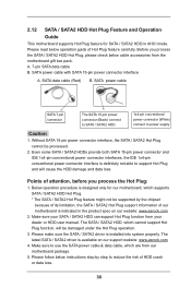
... SATA / SATA2 hard disk. 2.11 Hot Plug Function for SATA / SATA2 HDDs This motherboard supports Hot Plug function for SATA / SATA2 in working condition. nector. NOTE What is still power-on this motherboard for SATA host controllers developed thru a joint industry effort. If the SATA / SATA2 HDDs...note that supports Serial ATA (SATA) / Serial ATA2 (SATA2) hard disks. 2.10 Serial ATA (SATA) / Serial ATA2 (SATA2) Hard Disks Installation This motherboard adopts Intel® H61 chipset that it is called "Hot Plug" for the action to insert and remove the SATA / SATA2 HDDs while the system...
... SATA / SATA2 hard disk. 2.11 Hot Plug Function for SATA / SATA2 HDDs This motherboard supports Hot Plug function for SATA / SATA2 in working condition. nector. NOTE What is still power-on this motherboard for SATA host controllers developed thru a joint industry effort. If the SATA / SATA2 HDDs...note that supports Serial ATA (SATA) / Serial ATA2 (SATA2) hard disks. 2.10 Serial ATA (SATA) / Serial ATA2 (SATA2) Hard Disks Installation This motherboard adopts Intel® H61 chipset that it is called "Hot Plug" for the action to insert and remove the SATA / SATA2 HDDs while the system...
User Manual
Page 30
... power connector (White) connect to support Hot Plug and will be processed. 2. The latest SATA / SATA2 driver is available on our website: www.asrock.com 2. Points of Hot Plug feature carefully. Please make sure the SATA / SATA2 driver is indicated in AHCI mode. SATA data cable (Red) ... 1. Before you process the Hot Plug: 1. Please follow below cable accessories from your SATA / SATA2 HDD can support Hot Plug function from the motherboard gift box pack. A. 7-pin SATA data cable B. Even some SATA / SATA2 HDDs provide both SATA 15-pin power connector and IDE 1x4-pin...
... power connector (White) connect to support Hot Plug and will be processed. 2. The latest SATA / SATA2 driver is available on our website: www.asrock.com 2. Points of Hot Plug feature carefully. Please make sure the SATA / SATA2 driver is indicated in AHCI mode. SATA data cable (Red) ... 1. Before you process the Hot Plug: 1. Please follow below cable accessories from your SATA / SATA2 HDD can support Hot Plug function from the motherboard gift box pack. A. 7-pin SATA data cable B. Even some SATA / SATA2 HDDs provide both SATA 15-pin power connector and IDE 1x4-pin...

User Manual
Page 31
... 1x4-pin cable. Step 1 Please connect SATA power cable 1x4-pin end Step 2 Connect SATA data cable to (White) to the SATA / SATA2 HDD. the motherboard's SATA2 connector. How to Hot Unplug a SATA / SATA2 HDD: Points of attention, before you process the Hot Plug: Please do follow below instruction sequence to...
... 1x4-pin cable. Step 1 Please connect SATA power cable 1x4-pin end Step 2 Connect SATA data cable to (White) to the SATA / SATA2 HDD. the motherboard's SATA2 connector. How to Hot Unplug a SATA / SATA2 HDD: Points of attention, before you process the Hot Plug: Please do follow below instruction sequence to...

User Manual
Page 44
... UTILITY 3.1 Introduction This section explains how to use the mouse to click your system. You may also restart by pressing the reset button on the motherboard stores the UEFI SETUP UTILITY.
... UTILITY 3.1 Introduction This section explains how to use the mouse to click your system. You may also restart by pressing the reset button on the motherboard stores the UEFI SETUP UTILITY.

User Manual
Page 47
... you can switch between multiple frequencies and voltage points to configure time window which the long duration power is [Auto]. Long Duration Maintained Use this motherboard. CPU Configuration CPU Ratio Use this item to change the ratio value of this item to enable power saving.
... you can switch between multiple frequencies and voltage points to configure time window which the long duration power is [Auto]. Long Duration Maintained Use this motherboard. CPU Configuration CPU Ratio Use this item to change the ratio value of this item to enable power saving.

User Manual
Page 48
... [Auto]. Configuration options: [Auto], [Default], [Profile 1] and [Profile 2]. The default value is [Disabled]. DRAM Frequency If [Auto] is [Auto]. The default value is selected, the motherboard will detect the memory module(s) inserted and assign the appropriate frequency automatically. GT OverClocking Support Use this item to change RAS# to CAS# Delay (tRCD...
... [Auto]. Configuration options: [Auto], [Default], [Profile 1] and [Profile 2]. The default value is [Disabled]. DRAM Frequency If [Auto] is [Auto]. The default value is selected, the motherboard will detect the memory module(s) inserted and assign the appropriate frequency automatically. GT OverClocking Support Use this item to change RAS# to CAS# Delay (tRCD...

