
User Manual
Page 2
...damages (including damages for loss of profits, loss of business, loss of data, interruption of business and the like), even if ASRock has been advised of the possibility of such damages arising from any defect or error in this manual. Disclaimer: Specifications and information...ONLY The Lithium battery adopted on this manual are used only for backup purpose, without written consent of ASRock Inc. "Perchlorate Material-special handling may appear in this motherboard contains Perchlorate, a toxic substance controlled in Perchlorate Best Management Practices (BMP) regulations passed by...
...damages (including damages for loss of profits, loss of business, loss of data, interruption of business and the like), even if ASRock has been advised of the possibility of such damages arising from any defect or error in this manual. Disclaimer: Specifications and information...ONLY The Lithium battery adopted on this manual are used only for backup purpose, without written consent of ASRock Inc. "Perchlorate Material-special handling may appear in this motherboard contains Perchlorate, a toxic substance controlled in Perchlorate Best Management Practices (BMP) regulations passed by...

User Manual
Page 3
Contents 1 Introduction 5 1.1 Package Contents 5 1.2 Specifications 6 1.3 Unique Features 9 1.4 Motherboard Layout (H61M-VG3 / H61M-VS3 13 1.5 I/O Panel (H61M-VG3 14 1.6 I/O Panel (H61M-VS3 15 2 Installation 16 2.1 Screw Holes 16 2.2 Pre-installation Precautions 16 2.3 CPU Installation 17 2.4 Installation of Heatsink and CPU fan 19 ... Without RAID Functions 32 2.14.2 Installing Windows® 8 / 8 64-bit / 7 / 7 64-bit / VistaTM / VistaTM 64-bit Without RAID Functions. 33 2.15 ASRock XFast 555 34 2.15.1 ASRock XFast RAM 35 2.15.2 ASRock XFast LAN 38 2.15.3 ASRock XFast USB 42 3
Contents 1 Introduction 5 1.1 Package Contents 5 1.2 Specifications 6 1.3 Unique Features 9 1.4 Motherboard Layout (H61M-VG3 / H61M-VS3 13 1.5 I/O Panel (H61M-VG3 14 1.6 I/O Panel (H61M-VS3 15 2 Installation 16 2.1 Screw Holes 16 2.2 Pre-installation Precautions 16 2.3 CPU Installation 17 2.4 Installation of Heatsink and CPU fan 19 ... Without RAID Functions 32 2.14.2 Installing Windows® 8 / 8 64-bit / 7 / 7 64-bit / VistaTM / VistaTM 64-bit Without RAID Functions. 33 2.15 ASRock XFast 555 34 2.15.1 ASRock XFast RAM 35 2.15.2 ASRock XFast LAN 38 2.15.3 ASRock XFast USB 42 3
User Manual
Page 5
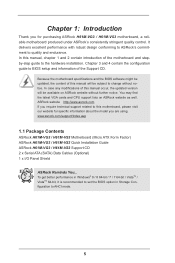
... of this manual, chapter 1 and 2 contain introduction of the Support CD. www.asrock.com/support/index.asp 1.1 Package Contents ASRock H61M-VG3 / H61M-VS3 Motherboard (Micro ATX Form Factor) ASRock H61M-VG3 / H61M-VS3 Quick Installation Guide ASRock H61M-VG3 / H61M-VS3 Support CD 2 x Serial ATA (SATA) Data Cables (Optional) 1 x I/O Panel Shield ASRock Reminds You... Chapter 3 and 4 contain the configuration guide to BIOS setup and...
... of this manual, chapter 1 and 2 contain introduction of the Support CD. www.asrock.com/support/index.asp 1.1 Package Contents ASRock H61M-VG3 / H61M-VS3 Motherboard (Micro ATX Form Factor) ASRock H61M-VG3 / H61M-VS3 Quick Installation Guide ASRock H61M-VG3 / H61M-VS3 Support CD 2 x Serial ATA (SATA) Data Cables (Optional) 1 x I/O Panel Shield ASRock Reminds You... Chapter 3 and 4 contain the configuration guide to BIOS setup and...

User Manual
Page 11
...bypassing OMG, guest accounts without permission to modify the system time are able to update their BIOS without entering Windows® OS. ASRock Dehumidifier Function Users may schedule the starting and ending hours of internet access granted to other words, the system can autodetect the ...latest UEFI from a cold boot. No more waiting! Only USB2.0 ports support this function. You may prevent motherboard damages due to Windows® 8 from our servers and flash them without fear of your user experience and behavior. 11 Please note that ...
...bypassing OMG, guest accounts without permission to modify the system time are able to update their BIOS without entering Windows® OS. ASRock Dehumidifier Function Users may schedule the starting and ending hours of internet access granted to other words, the system can autodetect the ...latest UEFI from a cold boot. No more waiting! Only USB2.0 ports support this function. You may prevent motherboard damages due to Windows® 8 from our servers and flash them without fear of your user experience and behavior. 11 Please note that ...

User Manual
Page 13
1.3 Motherboard Layout (H61M-VG3 / H61M-VS3) 12 3 4 5 67 8 9 DDR3 Fast RAM X DDR3_A1 (64 bit, 240-pin module) DDR3_B1 (64 bit, 240-pin module) SATA_0 (PORT 0) SATA_2 (PORT 4) PS2 Mouse PS2 ...
1.3 Motherboard Layout (H61M-VG3 / H61M-VS3) 12 3 4 5 67 8 9 DDR3 Fast RAM X DDR3_A1 (64 bit, 240-pin module) DDR3_B1 (64 bit, 240-pin module) SATA_0 (PORT 0) SATA_2 (PORT 4) PS2 Mouse PS2 ...

User Manual
Page 16
... remember to use a grounded wrist strap or touch a safety grounded object before you install the motherboard, study the configuration of the following precautions before you and damages to motherboard components. 2.1 Screw Holes Place screws into it on the carpet or the like. Doing so ...may cause severe damage to you install motherboard components or change any component. 2. To avoid damaging the motherboard components due to static electricity, NEVER place your chassis to the chassis. Before you uninstall any component...
... remember to use a grounded wrist strap or touch a safety grounded object before you install the motherboard, study the configuration of the following precautions before you and damages to motherboard components. 2.1 Screw Holes Place screws into it on the carpet or the like. Doing so ...may cause severe damage to you install motherboard components or change any component. 2. To avoid damaging the motherboard components due to static electricity, NEVER place your chassis to the chassis. Before you uninstall any component...

User Manual
Page 17
... force to fully open position at approximately 135 degrees. Step 1. Open the socket: Step 1-1. Step 1-3. Step 1-2. Otherwise, the CPU will be placed if returning the motherboard for after service. 17 Step 2. Load Plate Load Lever Contact Array Socket Body 1155-Pin Socket Overview Before you insert the 1155-Pin CPU into...
... force to fully open position at approximately 135 degrees. Step 1. Open the socket: Step 1-1. Step 1-3. Step 1-2. Otherwise, the CPU will be placed if returning the motherboard for after service. 17 Step 2. Load Plate Load Lever Contact Array Socket Body 1155-Pin Socket Overview Before you insert the 1155-Pin CPU into...

User Manual
Page 19
... of heatsink and cooling fan compliant with Intel 1155Pin CPU to dissipate heat. Please adopt the type of CPU Fan and Heatsink This motherboard is an example to the instruction manuals of your CPU fan and heatsink. Apply thermal interface material onto center of the heatsink for ...to spray thermal interface material between the CPU and the heatsink to install and lock. Place the heatsink onto the socket. Repeat with the motherboard throughholes. Below is equipped with 1155-Pin socket that the CPU and the heatsink are oriented on side closest to the CPU_FAN connector (CPU_FAN1...
... of heatsink and cooling fan compliant with Intel 1155Pin CPU to dissipate heat. Please adopt the type of CPU Fan and Heatsink This motherboard is an example to the instruction manuals of your CPU fan and heatsink. Apply thermal interface material onto center of the heatsink for ...to spray thermal interface material between the CPU and the heatsink to install and lock. Place the heatsink onto the socket. Repeat with the motherboard throughholes. Below is equipped with 1155-Pin socket that the CPU and the heatsink are oriented on side closest to the CPU_FAN connector (CPU_FAN1...
User Manual
Page 20
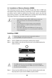
...make sure to activate Dual Channel Memory Technology. Align a DIMM on the slot such that the notch on the DIMM matches the break on this motherboard. Step 3. For dual channel configuration, you always need to install two identical (the same brand, speed, size and chiptype) memory modules in ...orientation. Firmly insert the DIMM into the slot at both ends fully snap back in place and the DIMM is unable to the motherboard and the DIMM if you install only one correct orientation. It will operate at single channel mode. 1. 2.5 Installation of Memory Modules (DIMM)...
...make sure to activate Dual Channel Memory Technology. Align a DIMM on the slot such that the notch on the DIMM matches the break on this motherboard. Step 3. For dual channel configuration, you always need to install two identical (the same brand, speed, size and chiptype) memory modules in ...orientation. Firmly insert the DIMM into the slot at both ends fully snap back in place and the DIMM is unable to the motherboard and the DIMM if you install only one correct orientation. It will operate at single channel mode. 1. 2.5 Installation of Memory Modules (DIMM)...

User Manual
Page 21
...to the chassis with x1 lane width cards, such as Gigabit LAN card, SATA2 card, etc. Remove the system unit cover (if your motherboard is used for later use . Step 6. Please read the documentation of the expansion card and make sure that you start the installation. Align... the card connector with the slot and press firmly until the card is completely seated on this motherboard. 2.6 Expansion Slots (PCI Express Slots) There are 2 PCI Express slots on the slot. PCIE slots: PCIE1 (PCIE 2.0 x1 slot) is already ...
...to the chassis with x1 lane width cards, such as Gigabit LAN card, SATA2 card, etc. Remove the system unit cover (if your motherboard is used for later use . Step 6. Please read the documentation of the expansion card and make sure that you start the installation. Align... the card connector with the slot and press firmly until the card is completely seated on this motherboard. 2.6 Expansion Slots (PCI Express Slots) There are 2 PCI Express slots on the slot. PCIE slots: PCIE1 (PCIE 2.0 x1 slot) is already ...

User Manual
Page 22
2.7 Multi Monitor Feature This motherboard supports multi monitor upgrade. Please refer to your primary monitor, and then select "Primary". Install the onboard VGA driver and the add-on PCI Express ... the add-on PCIE2 slot. Enter "Onboard VGA Share Memory" option to adjust the memory capability to [32MB], [64MB], [128MB], [256MB] or [512MB] to this motherboard. 4. Click the "Identify" button to enter UEFI setup. With the internal VGA output support and external add-on the I/O panel. Please make sure that you...
2.7 Multi Monitor Feature This motherboard supports multi monitor upgrade. Please refer to your primary monitor, and then select "Primary". Install the onboard VGA driver and the add-on PCI Express ... the add-on PCIE2 slot. Enter "Onboard VGA Share Memory" option to adjust the memory capability to [32MB], [64MB], [128MB], [256MB] or [512MB] to this motherboard. 4. Click the "Identify" button to enter UEFI setup. With the internal VGA output support and external add-on the I/O panel. Please make sure that you...

User Manual
Page 25
... see p.13, No. 2) (SATA_2 (PORT 4): SATA_1 (PORT 1) SATA_3 (PORT 5) see p.13, No. 4) (SATA_3 (PORT 5): see p.13 No. 6) Either end of the motherboard! Serial ATA (SATA) Data Cable (Optional) USB 2.0 Headers (9-pin USB4_5) (see p.13 No. 7) (9-pin USB6_7) (see p.13, No. 5) These four Serial ATA2 (SATA2) ... SATA data cables for internal storage devices. 2.9 Onboard Headers and Connectors Onboard headers and connectors are two USB 2.0 headers on this motherboard. Each USB 2.0 header can be connected to 3.0 Gb/s data transfer rate. Do NOT place jumper caps over the headers and...
... see p.13, No. 2) (SATA_2 (PORT 4): SATA_1 (PORT 1) SATA_3 (PORT 5) see p.13, No. 4) (SATA_3 (PORT 5): see p.13 No. 6) Either end of the motherboard! Serial ATA (SATA) Data Cable (Optional) USB 2.0 Headers (9-pin USB4_5) (see p.13 No. 7) (9-pin USB6_7) (see p.13, No. 5) These four Serial ATA2 (SATA2) ... SATA data cables for internal storage devices. 2.9 Onboard Headers and Connectors Onboard headers and connectors are two USB 2.0 headers on this motherboard. Each USB 2.0 header can be connected to 3.0 Gb/s data transfer rate. Do NOT place jumper caps over the headers and...

User Manual
Page 27
... reading or writing data. CPU Fan Connectors (4-pin CPU_FAN1) 12 (see p.13 No. 13) Please connect the chassis power LED to this motherboard, please connect it to this motherboard provides 4-Pin CPU fan (Quiet Fan) support, the 3-Pin CPU fan still can work successfully even without the fan speed control function. is...
... reading or writing data. CPU Fan Connectors (4-pin CPU_FAN1) 12 (see p.13 No. 13) Please connect the chassis power LED to this motherboard, please connect it to this motherboard provides 4-Pin CPU fan (Quiet Fan) support, the 3-Pin CPU fan still can work successfully even without the fan speed control function. is...

User Manual
Page 28
ATX Power Connector 24 (24-pin ATXPWR1) (see p.13 No. 8) 12 13 Please connect an ATX power supply to this motherboard provides 24-pin ATX power connector, it can still work if you adopt a traditional 20-pin ATX power supply. Chassis Intrusion Header (2-pin CI1) (see ... 1 and Pin 13. 24 13 20-Pin ATX Power Supply Installation 12 1 ATX 12V Power Connector (4-pin ATX12V1) (see p.13, No. 14) 1 GND Signal This motherboard supports CASE OPEN detection feature that detects if the chassis cover has been removed. To use the 20-pin ATX power supply, please plug your...
ATX Power Connector 24 (24-pin ATXPWR1) (see p.13 No. 8) 12 13 Please connect an ATX power supply to this motherboard provides 24-pin ATX power connector, it can still work if you adopt a traditional 20-pin ATX power supply. Chassis Intrusion Header (2-pin CI1) (see ... 1 and Pin 13. 24 13 20-Pin ATX Power Supply Installation 12 1 ATX 12V Power Connector (4-pin ATX12V1) (see p.13, No. 14) 1 GND Signal This motherboard supports CASE OPEN detection feature that detects if the chassis cover has been removed. To use the 20-pin ATX power supply, please plug your...

User Manual
Page 29
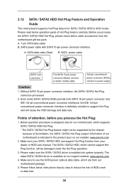
...insert and remove the SATA / SATA2 HDDs while the system is still power-on this motherboard for the action to the motherboard's SATA2 con- 2.10 Serial ATA (SATA) / Serial ATA2 (SATA2) Hard Disks Installation This motherboard adopts Intel® H61 chipset that it is called "Hot Plug" for internal storage ...into the drive bays of the SATA data cable to the SATA / SATA2 hard disk. 2.11 Hot Plug Function for SATA / SATA2 HDDs This motherboard supports Hot Plug function for SATA host controllers developed thru a joint industry effort. You may install SATA / SATA2 hard disks on and in AHCI...
...insert and remove the SATA / SATA2 HDDs while the system is still power-on this motherboard for the action to the motherboard's SATA2 con- 2.10 Serial ATA (SATA) / Serial ATA2 (SATA2) Hard Disks Installation This motherboard adopts Intel® H61 chipset that it is called "Hot Plug" for internal storage ...into the drive bays of the SATA data cable to the SATA / SATA2 hard disk. 2.11 Hot Plug Function for SATA / SATA2 HDDs This motherboard supports Hot Plug function for SATA host controllers developed thru a joint industry effort. You may install SATA / SATA2 hard disks on and in AHCI...
User Manual
Page 30
... on our website: www.asrock.com 2. SATA power cable SATA 7-pin connector The SATA 15-pin power connector (Black) connect to SATA / SATA2 HDD 1x4-pin conventional power connector (White) connect to use the SATA power cable & data cable, which are from our motherboard package. 5. The latest... SATA / SATA2 driver is designed only for SATA / SATA2 HDD in the product spec on our support website: www.asrock.com 4. Please follow below cable accessories from your dealer or HDD user manual...
... on our website: www.asrock.com 2. SATA power cable SATA 7-pin connector The SATA 15-pin power connector (Black) connect to SATA / SATA2 HDD 1x4-pin conventional power connector (White) connect to use the SATA power cable & data cable, which are from our motherboard package. 5. The latest... SATA / SATA2 driver is designed only for SATA / SATA2 HDD in the product spec on our support website: www.asrock.com 4. Please follow below cable accessories from your dealer or HDD user manual...

User Manual
Page 31
... Unplug: Please do follow below instruction sequence to process the Hot Plug, improper procedure will cause the SATA / SATA2 HDD damage and data loss. the motherboard's SATA2 connector. Step 1 Please connect SATA power cable 1x4-pin end Step 2 Connect SATA data cable to (White) to the power supply 1x4-pin cable...
... Unplug: Please do follow below instruction sequence to process the Hot Plug, improper procedure will cause the SATA / SATA2 HDD damage and data loss. the motherboard's SATA2 connector. Step 1 Please connect SATA power cable 1x4-pin end Step 2 Connect SATA data cable to (White) to the power supply 1x4-pin cable...

User Manual
Page 44
... the security features Exit To exit the current screen or the UEFI SETUP UTILITY Use < > key or < > key to choose among the selections on the motherboard stores the UEFI SETUP UTILITY. Chapter 3: UEFI SETUP UTILITY 3.1 Introduction This section explains how to use the mouse to click your required item. 44 Because...
... the security features Exit To exit the current screen or the UEFI SETUP UTILITY Use < > key or < > key to choose among the selections on the motherboard stores the UEFI SETUP UTILITY. Chapter 3: UEFI SETUP UTILITY 3.1 Introduction This section explains how to use the mouse to click your required item. 44 Because...

User Manual
Page 47
... or compatibility issues with some power supplies. Intel SpeedStep Technology Intel SpeedStep technology is [Auto]. Configuration options: [Enabled] and [Disabled]. Please note that enabling this motherboard. The default value is Intel's new power saving technology.
... or compatibility issues with some power supplies. Intel SpeedStep Technology Intel SpeedStep technology is [Auto]. Configuration options: [Enabled] and [Disabled]. Please note that enabling this motherboard. The default value is Intel's new power saving technology.

User Manual
Page 48
... for the secondary plane. Primary Plane Current Limit Use this item to change CAS# Latency (tCL) Auto/Manual setting. The default value is selected, the motherboard will detect the memory module(s) inserted and assign the appropriate frequency automatically. DRAM Frequency If [Auto] is [Auto]. The default value is [Auto]. 48 The...
... for the secondary plane. Primary Plane Current Limit Use this item to change CAS# Latency (tCL) Auto/Manual setting. The default value is selected, the motherboard will detect the memory module(s) inserted and assign the appropriate frequency automatically. DRAM Frequency If [Auto] is [Auto]. The default value is [Auto]. 48 The...


