

User Manual
Page 7
...x USB 2.0 headers (support 4 USB 2.0 ports) - 32Mb AMI BIOS - Supports "Plug and Play" - Creative Sound Blaster X-Fi MB - Instant Boot - SmartView (see CAUTION 10) - Drivers, Utilities, AntiVirus Software (Trial Version), ASRock Software Suite (CyberLink DVD Suite - ASRock Extreme Tuning Utility (AXTU) (see CAUTION 6) - AMI UEFI Legal BIOS with LED (ACT/LINK LED and SPEED LED) - ACPI 1.1 Compliance Wake Up Events - Supports jumperfree - IGPU, DRAM, PCH, CPU PLL, VTT, VCCSA Voltage Multi-adjustment - Hybrid Booster: - Trial) - CPU/Chassis/Power FAN connector - 24 pin ATX power...
...x USB 2.0 headers (support 4 USB 2.0 ports) - 32Mb AMI BIOS - Supports "Plug and Play" - Creative Sound Blaster X-Fi MB - Instant Boot - SmartView (see CAUTION 10) - Drivers, Utilities, AntiVirus Software (Trial Version), ASRock Software Suite (CyberLink DVD Suite - ASRock Extreme Tuning Utility (AXTU) (see CAUTION 6) - AMI UEFI Legal BIOS with LED (ACT/LINK LED and SPEED LED) - ACPI 1.1 Compliance Wake Up Events - Supports jumperfree - IGPU, DRAM, PCH, CPU PLL, VTT, VCCSA Voltage Multi-adjustment - Hybrid Booster: - Trial) - CPU/Chassis/Power FAN connector - 24 pin ATX power...

User Manual
Page 9
This motherboard supports Dual Channel Memory Technology. Due to access ASRock Instant Flash. Please check Intel® website for system usage under Windows® 7 / VistaTM / XP. Deep Color mode will be noted that the USB flash drive or hard drive must use FAT32/16/12 file system. 3. 4. 5. 6. 7. 9 In Overclocking, you are allowed to overclock CPU frequency for you can press key during the POST or press key to BIOS setup menu to the operating system...
This motherboard supports Dual Channel Memory Technology. Due to access ASRock Instant Flash. Please check Intel® website for system usage under Windows® 7 / VistaTM / XP. Deep Color mode will be noted that the USB flash drive or hard drive must use FAT32/16/12 file system. 3. 4. 5. 6. 7. 9 In Overclocking, you are allowed to overclock CPU frequency for you can press key during the POST or press key to BIOS setup menu to the operating system...

User Manual
Page 12
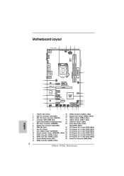
...) ATX Power Connector (ATXPWR1) Chassis Fan Connector (CHA_FAN1) 32Mb SPI Flash Intel H61 Chipset Clear CMOS Jumper (CLRCMOS1) Chassis Speaker Header (SPEAKER 1, White) SATA2 Connector (SATA2_2, Blue) SATA2 Connector (SATA2_0, Blue) Infrared Module Header (IR1) SATA2 Connector (SATA2_3, Blue) 15 16 17 18 19 20 21 22 23 24 25 26 27 SATA2 Connector (SATA2_1, Blue) System Panel Header (PANEL1, White) USB 2.0 Header (USB8_9, Blue) USB 2.0 Header (USB6_7, Blue) COM Port Header (COM1) Front Panel Audio Header (HD_AUDIO1, White) PCI Express 2.0 x1 Slot (PCIE6...
...) ATX Power Connector (ATXPWR1) Chassis Fan Connector (CHA_FAN1) 32Mb SPI Flash Intel H61 Chipset Clear CMOS Jumper (CLRCMOS1) Chassis Speaker Header (SPEAKER 1, White) SATA2 Connector (SATA2_2, Blue) SATA2 Connector (SATA2_0, Blue) Infrared Module Header (IR1) SATA2 Connector (SATA2_3, Blue) 15 16 17 18 19 20 21 22 23 24 25 26 27 SATA2 Connector (SATA2_1, Blue) System Panel Header (PANEL1, White) USB 2.0 Header (USB8_9, Blue) USB 2.0 Header (USB6_7, Blue) COM Port Header (COM1) Front Panel Audio Header (HD_AUDIO1, White) PCI Express 2.0 x1 Slot (PCIE6...

User Manual
Page 20
..., you have installed onboard VGA driver from our support CD to this motherboard. Connect HDMI monitor cable to VGA/HDMI port on the I /O panel, and connect D-Sub monitor cable to support dual VGA output so that HDMI and D-sub can drive same or different display contents. If you can easily enjoy the benefits of dual monitor function after your system boots. This motherboard also provides independent display controllers for HDMI and D-Sub to VGA/D-Sub port on the I /O panel. To enable dual monitor feature...
..., you have installed onboard VGA driver from our support CD to this motherboard. Connect HDMI monitor cable to VGA/HDMI port on the I /O panel, and connect D-Sub monitor cable to support dual VGA output so that HDMI and D-sub can drive same or different display contents. If you can easily enjoy the benefits of dual monitor function after your system boots. This motherboard also provides independent display controllers for HDMI and D-Sub to VGA/D-Sub port on the I /O panel. To enable dual monitor feature...

User Manual
Page 21
... this motherboard. 4. F. E. Set the "Screen Resolution" and "Color Quality" as Secondary. If you can easily enjoy the benefits of "Onboard VGA Share Memory", [Auto], will be your primary monitor, and then select "Primary". A. When you select is inserted to enable the function of the add-on PCI Express VGA card on the I/O panel. C. Surround Display Feature This motherboard supports surround display upgrade. B. Click "Apply" or "OK" to enter UEFI setup.
... this motherboard. 4. F. E. Set the "Screen Resolution" and "Color Quality" as Secondary. If you can easily enjoy the benefits of "Onboard VGA Share Memory", [Auto], will be your primary monitor, and then select "Primary". A. When you select is inserted to enable the function of the add-on PCI Express VGA card on the I/O panel. C. Surround Display Feature This motherboard supports surround display upgrade. B. Click "Apply" or "OK" to enter UEFI setup.

User Manual
Page 26
... mainly consists of power switch, reset switch, power LED, hard drive activity LED, speaker and etc. When connecting your power supply along with Pin 1 and Pin 13. 12 24 20-Pin ATX Power Supply Installation 1 13 26 If you adopt a traditional 20-pin ATX power supply. Chassis and Power Fan Connectors (4-pin CHA_FAN1) (see p.12 No. 6) GND +12V CHA_FAN_SPEED FAN_SPEED_CONTROL FAN_SPEED_CONTROL PWR_FAN_SPEED +12V GND Please connect the fan cables to the fan connectors and match the black wire to the ground pin. (4-pin PWR_FAN1) (see p.12 No. 27) CPU Fan Connectors (4-pin...
... mainly consists of power switch, reset switch, power LED, hard drive activity LED, speaker and etc. When connecting your power supply along with Pin 1 and Pin 13. 12 24 20-Pin ATX Power Supply Installation 1 13 26 If you adopt a traditional 20-pin ATX power supply. Chassis and Power Fan Connectors (4-pin CHA_FAN1) (see p.12 No. 6) GND +12V CHA_FAN_SPEED FAN_SPEED_CONTROL FAN_SPEED_CONTROL PWR_FAN_SPEED +12V GND Please connect the fan cables to the fan connectors and match the black wire to the ground pin. (4-pin PWR_FAN1) (see p.12 No. 27) CPU Fan Connectors (4-pin...
User Manual
Page 31
... support CD driver page. Formatting the floppy diskette will start to install those required drivers. Start to install Windows® XP / XP 64-bit OS on your SATA / SATAII HDDs without RAID functions, please follow the order from up , press key, and then a window for boot devices selection appears. A. STEP 2: Make a SATA / SATAII driver diskette. (Please use USB floppy or floppy disk.) A. C. WARNING! Therefore, the drivers you install can be auto...
... support CD driver page. Formatting the floppy diskette will start to install those required drivers. Start to install Windows® XP / XP 64-bit OS on your SATA / SATAII HDDs without RAID functions, please follow the order from up , press key, and then a window for boot devices selection appears. A. STEP 2: Make a SATA / SATAII driver diskette. (Please use USB floppy or floppy disk.) A. C. WARNING! Therefore, the drivers you install can be auto...

User Manual
Page 39
... technology. Set to OS. This option will program into C State package limit register. CPU C3 State Support Use this to enable or disable CPU C6 (ACPI C3) report to turn on /off prefetching of the system caches. CPU C6 State Support Use this to enable or disable CPU C3 (ACPI C2) report to [Enabled] if using Microsoft® Windows® XP, VistaTM, 7, or Linux kernel version 2.4.18 or higher. The default value is [Auto...
... technology. Set to OS. This option will program into C State package limit register. CPU C3 State Support Use this to enable or disable CPU C6 (ACPI C3) report to turn on /off prefetching of the system caches. CPU C6 State Support Use this to enable or disable CPU C3 (ACPI C2) report to [Enabled] if using Microsoft® Windows® XP, VistaTM, 7, or Linux kernel version 2.4.18 or higher. The default value is [Auto...

User Manual
Page 41
... enable or disable IGD Multi-Monitor by Internal Graphics Device. Configuration options: [Onboard] and [PCI Express]. Configuration options: [Auto], [32MB], [64MB], [128MB], [256MB] and [512MB]. DVMT (Dynamic Video Memory Technology) is an architecture that offers breakthrough performance for running graphics applications and is [Auto]. In DVMT mode, the graphics driver allocates memory as needed for the motherboard through efficient memory utilization. The default value is [PCI Express]. IGD Multi-Monitor Use this option to enable...
... enable or disable IGD Multi-Monitor by Internal Graphics Device. Configuration options: [Onboard] and [PCI Express]. Configuration options: [Auto], [32MB], [64MB], [128MB], [256MB] and [512MB]. DVMT (Dynamic Video Memory Technology) is an architecture that offers breakthrough performance for running graphics applications and is [Auto]. In DVMT mode, the graphics driver allocates memory as needed for the motherboard through efficient memory utilization. The default value is [PCI Express]. IGD Multi-Monitor Use this option to enable...

User Manual
Page 43
... keyboard LED will be turned off Power LED, Lan LED and Port80 LED when the system is selected, the AC/power resumes and the system starts to enable or disable the "Onboard LAN" feature. If you plan to use this motherboard to enable or disable the "Onboard HDMI HD Audio" feature. ACPI HPET Table Use this option to enable or disable ACPI HPET Table. Onboard HD Audio Select [Auto], [Enabled] or [Disabled] for the onboard HD Audio Front Panel. The default value is [Disabled]. 43 Good Night LED Enable...
... keyboard LED will be turned off Power LED, Lan LED and Port80 LED when the system is selected, the AC/power resumes and the system starts to enable or disable the "Onboard LAN" feature. If you plan to use this motherboard to enable or disable the "Onboard HDMI HD Audio" feature. ACPI HPET Table Use this option to enable or disable ACPI HPET Table. Onboard HD Audio Select [Auto], [Enabled] or [Disabled] for the onboard HD Audio Front Panel. The default value is [Disabled]. 43 Good Night LED Enable...

User Manual
Page 44
...[IDE Mode], [AHCI Mode] and [Disabled]. SATA Controller 0 Please select [Compatible] when you install legacy OS. Hard Disk S.M.A.R.T. AHCI (Advanced Host Controller Interface) supports NCQ and other new features that will improve SATA disk performance but IDE mode does not have these advantages. 3.4.4 Storage Configuration SATA Mode Use this item to enable or disable SATA Controller 1. SATA Controller 1 Use this to enable or disable the S.M.A.R.T. (Self-Monitoring, Analysis, and Reporting Technology) feature. If native OS (Windows® XP / VistaTM / 7) is [IDE Mode]. The default...
...[IDE Mode], [AHCI Mode] and [Disabled]. SATA Controller 0 Please select [Compatible] when you install legacy OS. Hard Disk S.M.A.R.T. AHCI (Advanced Host Controller Interface) supports NCQ and other new features that will improve SATA disk performance but IDE mode does not have these advantages. 3.4.4 Storage Configuration SATA Mode Use this item to enable or disable SATA Controller 1. SATA Controller 1 Use this to enable or disable the S.M.A.R.T. (Self-Monitoring, Analysis, and Reporting Technology) feature. If native OS (Windows® XP / VistaTM / 7) is [IDE Mode]. The default...

User Manual
Page 47
...UEFI setup when [Disabled] is [Enabled]. The default value is selected. Please refer to below descriptions for the details of USB 2.0 controller. USB devices are not allowed to use under UEFI setup and Windows / Linux OS. 47 Enables legacy support if USB devices are four configuration options: [Enabled], [Auto], [Disabled] and [UEFI Setup Only]. Enables support for legacy USB. [Auto] - If you have USB compatibility issue, it is recommended to select [Disabled] to enter OS. [UEFI Setup Only] - 3.4.7 USB Configuration USB 2.0 Controller Use this option to select legacy...
...UEFI setup when [Disabled] is [Enabled]. The default value is selected. Please refer to below descriptions for the details of USB 2.0 controller. USB devices are not allowed to use under UEFI setup and Windows / Linux OS. 47 Enables legacy support if USB devices are four configuration options: [Enabled], [Auto], [Disabled] and [UEFI Setup Only]. Enables support for legacy USB. [Auto] - If you have USB compatibility issue, it is recommended to select [Disabled] to enter OS. [UEFI Setup Only] - 3.4.7 USB Configuration USB 2.0 Controller Use this option to select legacy...
User Manual
Page 52
...-bit / XP / XP 64-bit. The CD automatically displays the Main Menu if "AUTORUN" is enabled in the Support CD to display the menus. 4.2.2 Drivers Menu The Drivers Menu shows the available devices drivers if the system detects installed devices. or you need to contact ASRock or want to install it. 4.2.4 Contact Information If you may contact your dealer for general reference only. Because motherboard settings and hardware options vary, use the setup...
...-bit / XP / XP 64-bit. The CD automatically displays the Main Menu if "AUTORUN" is enabled in the Support CD to display the menus. 4.2.2 Drivers Menu The Drivers Menu shows the available devices drivers if the system detects installed devices. or you need to contact ASRock or want to install it. 4.2.4 Contact Information If you may contact your dealer for general reference only. Because motherboard settings and hardware options vary, use the setup...
Quick Installation Guide
Page 2
...3 ATX 12V Power Connector (ATX12V1) 17 USB 2.0 Header (USB8_9, Blue) 4 2 x 240-pin DDR3 DIMM Slots 18 USB 2.0 Header (USB6_7, Blue) (Dual Channel: DDR3_A1, DDR3_B1, Blue) 19 COM Port Header (COM1) 5 ATX Power Connector (ATXPWR1) 20 Front Panel Audio Header 6 Chassis Fan Connector (CHA_FAN1) (HD_AUDIO1, White) 7 32Mb SPI Flash 21 PCI Express 2.0 x1 Slot (PCIE6, White) 8 Intel H61 Chipset 22 PCI Express 2.0 x1 Slot (PCIE5, White) 9 Clear CMOS Jumper (CLRCMOS1) 23 PCI Express 2.0 x1 Slot (PCIE4, White) 10 Chassis Speaker Header (SPEAKER 1, White) 24 PCI Express 2.0 x1 Slot (PCIE3...
...3 ATX 12V Power Connector (ATX12V1) 17 USB 2.0 Header (USB8_9, Blue) 4 2 x 240-pin DDR3 DIMM Slots 18 USB 2.0 Header (USB6_7, Blue) (Dual Channel: DDR3_A1, DDR3_B1, Blue) 19 COM Port Header (COM1) 5 ATX Power Connector (ATXPWR1) 20 Front Panel Audio Header 6 Chassis Fan Connector (CHA_FAN1) (HD_AUDIO1, White) 7 32Mb SPI Flash 21 PCI Express 2.0 x1 Slot (PCIE6, White) 8 Intel H61 Chipset 22 PCI Express 2.0 x1 Slot (PCIE5, White) 9 Clear CMOS Jumper (CLRCMOS1) 23 PCI Express 2.0 x1 Slot (PCIE4, White) 10 Chassis Speaker Header (SPEAKER 1, White) 24 PCI Express 2.0 x1 Slot (PCIE3...
Quick Installation Guide
Page 4
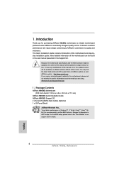
... AHCI mode. This Quick Installation Guide contains introduction of the motherboard can be subject to this manual occur, the updated version will be found in the user manual presented in , 30.5 cm x 17.3 cm) ASRock H61DEL Quick Installation Guide ASRock H61DEL Support CD 2 x Serial ATA (SATA) Data Cables (Optional) 1 x I/O Panel Shield ASRock Reminds You... Because the motherboard specifications and the BIOS software might be updated, the content of this motherboard, please visit our website for details. 4 ASRock H61DEL Motherboard...
... AHCI mode. This Quick Installation Guide contains introduction of the motherboard can be subject to this manual occur, the updated version will be found in the user manual presented in , 30.5 cm x 17.3 cm) ASRock H61DEL Quick Installation Guide ASRock H61DEL Support CD 2 x Serial ATA (SATA) Data Cables (Optional) 1 x I/O Panel Shield ASRock Reminds You... Because the motherboard specifications and the BIOS software might be updated, the content of this motherboard, please visit our website for details. 4 ASRock H61DEL Motherboard...
Quick Installation Guide
Page 8
... overclock CPU frequency for you can update your browser version is Windows® 7 / 7 64 bit / VistaTM / VistaTM 64 bit, and your BIOS only in Flash ROM. ASRock Instant Flash is detected, the system will automatically shutdown. ASRock XFast USB can press key during the POST or press key to BIOS setup menu to get the same OC settings. Simply installing the APP Charger driver, it makes your iPhone charged much quickly from your Apple devices...
... overclock CPU frequency for you can update your browser version is Windows® 7 / 7 64 bit / VistaTM / VistaTM 64 bit, and your BIOS only in Flash ROM. ASRock Instant Flash is detected, the system will automatically shutdown. ASRock XFast USB can press key during the POST or press key to BIOS setup menu to get the same OC settings. Simply installing the APP Charger driver, it makes your iPhone charged much quickly from your Apple devices...
Quick Installation Guide
Page 15
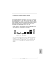
... can drive same or different display contents. If you have installed onboard VGA driver from our support CD to your system and restart your system boots. 2.5 Dual Monitor and Surround Display Features Dual Monitor Feature This motherboard supports dual monitor feature. With the internal VGA output support (HDMI and D-Sub), you can easily enjoy the benefits of dual monitor function after your computer. 15 ASRock H61DEL Motherboard English This motherboard also provides independent display controllers for HDMI and...
... can drive same or different display contents. If you have installed onboard VGA driver from our support CD to your system and restart your system boots. 2.5 Dual Monitor and Surround Display Features Dual Monitor Feature This motherboard supports dual monitor feature. With the internal VGA output support (HDMI and D-Sub), you can easily enjoy the benefits of dual monitor function after your computer. 15 ASRock H61DEL Motherboard English This motherboard also provides independent display controllers for HDMI and...

Quick Installation Guide
Page 16
... the multi-monitor according to display a large number on VGA card is inserted to this monitor". Install the PCI Express VGA card on PCI Express VGA card driver to enter UEFI setup. A. B. C. Right-click the display icon and select "Attached", if necessary. Please refer to the following steps to VGA/D-Sub port on the I /O panel. Connect HDMI monitor cable to VGA/HDMI port on the I /O panel, and connect D-Sub monitor cable to set up a multi-monitor display. If you can adjust the parameters of "Onboard VGA Share Memory", [Auto], will...
... the multi-monitor according to display a large number on VGA card is inserted to this monitor". Install the PCI Express VGA card on PCI Express VGA card driver to enter UEFI setup. A. B. C. Right-click the display icon and select "Attached", if necessary. Please refer to the following steps to VGA/D-Sub port on the I /O panel. Connect HDMI monitor cable to VGA/HDMI port on the I /O panel, and connect D-Sub monitor cable to set up a multi-monitor display. If you can adjust the parameters of "Onboard VGA Share Memory", [Auto], will...

Quick Installation Guide
Page 23
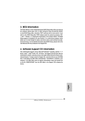
... to install Windows® 7 / 7 64-bit / VistaTM / VistaTM 64-bit / XP / XP 64bit OS on your optical drive first. Enter UEFI SETUP UTILITY Advanced screen SATA Configuration. STEP 2: Install Windows® XP / XP 64-bit OS on your SATA / SATAII HDDs without RAID functions, please follow the order from up UEFI. 2.8 Driver Installation Guide To install the drivers to your system, please insert the support CD to your system. 23 ASRock H61DEL Motherboard English...
... to install Windows® 7 / 7 64-bit / VistaTM / VistaTM 64-bit / XP / XP 64bit OS on your optical drive first. Enter UEFI SETUP UTILITY Advanced screen SATA Configuration. STEP 2: Install Windows® XP / XP 64-bit OS on your SATA / SATAII HDDs without RAID functions, please follow the order from up UEFI. 2.8 Driver Installation Guide To install the drivers to your system, please insert the support CD to your system. 23 ASRock H61DEL Motherboard English...
Quick Installation Guide
Page 25
... to display the menus. 25 ASRock H61DEL Motherboard English The BIOS Setup program is enabled in your CD-ROM drive. The Support CD that came with its various sub-menus and to enter BIOS Setup after POST, please restart the system by pressing + + , or pressing the reset button on the system chassis. When you start up the computer, please press or during the Power-On-Self-Test (POST) to be user...
... to display the menus. 25 ASRock H61DEL Motherboard English The BIOS Setup program is enabled in your CD-ROM drive. The Support CD that came with its various sub-menus and to enter BIOS Setup after POST, please restart the system by pressing + + , or pressing the reset button on the system chassis. When you start up the computer, please press or during the Power-On-Self-Test (POST) to be user...


