
Quick Installation Guide
Page 1
"Perchlorate Material-special handling may cause undesired operation. Operation is subject to the following two conditions: (1) this device may not cause harmful interference, and (2) this motherboard contains Perchlorate, a toxic substance controlled in advance. Version 1.0 Published April 2018 This device complies with Part 15 of the FCC Rules. When you discard the ...
"Perchlorate Material-special handling may cause undesired operation. Operation is subject to the following two conditions: (1) this device may not cause harmful interference, and (2) this motherboard contains Perchlorate, a toxic substance controlled in advance. Version 1.0 Published April 2018 This device complies with Part 15 of the FCC Rules. When you discard the ...
Quick Installation Guide
Page 3
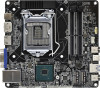
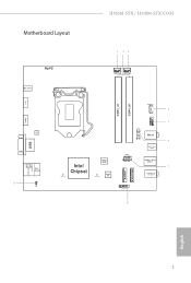
H310M-STX / H310M-STX/COM Motherboard Layout 1 23 RoHS DC Jack CPU_FAN2 CPU_FAN1 DP1 DDR4_A1 DDR4_B1 HDMI1 Audio CODEC VGA1 T: USB 2.0 USB3 B: USB 3.1 Gen1 USB4 Top: RJ-45 9 1 CI1 SPEAKER1 1 4 USB_5_6 5 1 COM1 Mic In 1 6 USB 3.1 Gen1 USB_2 Intel Chipset M2_1_CT1 BIOS ROM M2_2_CT1 Super I/O PANEL1 PLED PWRBTN 1 HDLED RESET USB 3.1 Gen1 USB_1 7 Headphone / Headset M.2 WiFi M.2 PCIe SSD 1 AUDIO3 8 English 1
H310M-STX / H310M-STX/COM Motherboard Layout 1 23 RoHS DC Jack CPU_FAN2 CPU_FAN1 DP1 DDR4_A1 DDR4_B1 HDMI1 Audio CODEC VGA1 T: USB 2.0 USB3 B: USB 3.1 Gen1 USB4 Top: RJ-45 9 1 CI1 SPEAKER1 1 4 USB_5_6 5 1 COM1 Mic In 1 6 USB 3.1 Gen1 USB_2 Intel Chipset M2_1_CT1 BIOS ROM M2_2_CT1 Super I/O PANEL1 PLED PWRBTN 1 HDLED RESET USB 3.1 Gen1 USB_1 7 Headphone / Headset M.2 WiFi M.2 PCIe SSD 1 AUDIO3 8 English 1
Quick Installation Guide
Page 8
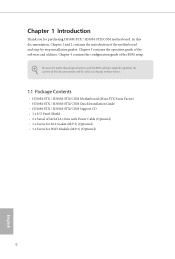
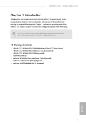
... to change without notice. 1.1 Package Contents • H310M-STX / H310M-STX/COM Motherboard (Mini-STX Form Factor) • H310M-STX / H310M-STX/COM Quick Installation Guide • H310M-STX / H310M-STX/COM Support CD • 1 x I/O Panel Shield • 2 x Serial ATA(SATA) Data with Power Cable (Optional) • 1 x Screw for M.2 Socket (M2*2) (Optional) • 1 x Screw for purchasing H310M-STX / H310M-STX/COM motherboard. Chapter 4 contains the configuration guide of the...
... to change without notice. 1.1 Package Contents • H310M-STX / H310M-STX/COM Motherboard (Mini-STX Form Factor) • H310M-STX / H310M-STX/COM Quick Installation Guide • H310M-STX / H310M-STX/COM Support CD • 1 x I/O Panel Shield • 2 x Serial ATA(SATA) Data with Power Cable (Optional) • 1 x Screw for M.2 Socket (M2*2) (Optional) • 1 x Screw for purchasing H310M-STX / H310M-STX/COM motherboard. Chapter 4 contains the configuration guide of the...

Quick Installation Guide
Page 13
... anti-static pad or in the bag that the motherboard fits into it. H310M-STX / H310M-STX/COM Chapter 2 Installation This is a Mini-STX form factor motherboard. Before you uninstall any motherboard settings. • Make sure to use a grounded wrist strap or touch a safety grounded object before you install motherboard components or change any components, place them on a carpet...
... anti-static pad or in the bag that the motherboard fits into it. H310M-STX / H310M-STX/COM Chapter 2 Installation This is a Mini-STX form factor motherboard. Before you uninstall any motherboard settings. • Make sure to use a grounded wrist strap or touch a safety grounded object before you install motherboard components or change any components, place them on a carpet...

Quick Installation Guide
Page 16
Please save and replace the cover if the processor is removed. The cover must be placed if you wish to return the motherboard for after service. 14 English
Please save and replace the cover if the processor is removed. The cover must be placed if you wish to return the motherboard for after service. 14 English

Quick Installation Guide
Page 18
The SO-DIMM only fits in one correct orientation. It will cause permanent damage to install a DDR, DDR2 or DDR3 memory module into the slot at incorrect orientation. 16 English It is not allowed to the motherboard and the SO-DIMM if you force the SO-DIMM into a DDR4 slot; 2.3 Installing Memory Modules (SO-DIMM) This motherboard provides two 260-pin DDR4 (Double Data Rate 4) SO-DIMM slots. otherwise, this motherboard and SO-DIMM may be damaged.
The SO-DIMM only fits in one correct orientation. It will cause permanent damage to install a DDR, DDR2 or DDR3 memory module into the slot at incorrect orientation. 16 English It is not allowed to the motherboard and the SO-DIMM if you force the SO-DIMM into a DDR4 slot; 2.3 Installing Memory Modules (SO-DIMM) This motherboard provides two 260-pin DDR4 (Double Data Rate 4) SO-DIMM slots. otherwise, this motherboard and SO-DIMM may be damaged.

Quick Installation Guide
Page 20
... to the pin assignments below. The LED is on the chassis front panel. The LED is off (S5). PLED (System Power LED): Connect to the motherboard. Do NOT place jumper caps over the headers and connectors will cause permanent damage to the power status indicator on when the system is on...
... to the pin assignments below. The LED is on the chassis front panel. The LED is off (S5). PLED (System Power LED): Connect to the motherboard. Do NOT place jumper caps over the headers and connectors will cause permanent damage to the power status indicator on when the system is on...

Quick Installation Guide
Page 21
... p.1, No. 5) DUMMY GND P+ P- CPU Fan Connectors (4-pin CPU_FAN1) (see p.1, No. 3) (4-pin CPU_FAN2) (see p.1, No. 4) Front_LFront_L+ Front_R+ Front_R- Please connect the chassis speaker to this motherboard. USB_PWR GND P+ PUSB_PWR 1 There is one header on this header. English 19 H310M-STX / H310M-STX/COM MONO Speaker Header 1 (4-pin SPEAKER1) (see p.1, No. 1) FAN_SPEED_CONTROL CPU_FAN_SPEED FAN_VOLTAGE GND 1 2 34 This...
... p.1, No. 5) DUMMY GND P+ P- CPU Fan Connectors (4-pin CPU_FAN1) (see p.1, No. 3) (4-pin CPU_FAN2) (see p.1, No. 4) Front_LFront_L+ Front_R+ Front_R- Please connect the chassis speaker to this motherboard. USB_PWR GND P+ PUSB_PWR 1 There is one header on this header. English 19 H310M-STX / H310M-STX/COM MONO Speaker Header 1 (4-pin SPEAKER1) (see p.1, No. 1) FAN_SPEED_CONTROL CPU_FAN_SPEED FAN_VOLTAGE GND 1 2 34 This...

Quick Installation Guide
Page 22
... This Audio header allows you to connect the audio cable for H310M-STX/COM only) (9-pin COM1) (see p.1, No. 6) RI NC This COM1 header RTS GND CTS DSR supports a serial port TXD DTR module. Clear CMOS Pad (see p.1, No. 9) GND Signal 1 This motherboard supports CASE OPEN detection feature that detects if the chassis...
... This Audio header allows you to connect the audio cable for H310M-STX/COM only) (9-pin COM1) (see p.1, No. 6) RI NC This COM1 header RTS GND CTS DSR supports a serial port TXD DTR module. Clear CMOS Pad (see p.1, No. 9) GND Signal 1 This motherboard supports CASE OPEN detection feature that detects if the chassis...

Quick Installation Guide
Page 27
H310M-STX / H310M-STX/COM 2.7 SD Card Installation Guide 1. Locate the SD Card Slot on the back side of the motherboard. 2. Carefully insert the SD Card into the slot until it clicks. 25 English
H310M-STX / H310M-STX/COM 2.7 SD Card Installation Guide 1. Locate the SD Card Slot on the back side of the motherboard. 2. Carefully insert the SD Card into the slot until it clicks. 25 English

Quick Installation Guide
Page 121
... harmful interference, and (2) this device must accept any interference received, including interference that the product Product Name : Motherboard Model Number : H310M-STX / H310M-STX/COM Conforms to the following two conditions: (1) is device complies with part 15 of the FCC Rules. Representative Person...'s Name: James Signature : Date : May 12, 2017 DECLARATION OF CONFORMITY Per FCC Part 2 Section 2.1077(a) Responsible Party Name: ASRock ...
... harmful interference, and (2) this device must accept any interference received, including interference that the product Product Name : Motherboard Model Number : H310M-STX / H310M-STX/COM Conforms to the following two conditions: (1) is device complies with part 15 of the FCC Rules. Representative Person...'s Name: James Signature : Date : May 12, 2017 DECLARATION OF CONFORMITY Per FCC Part 2 Section 2.1077(a) Responsible Party Name: ASRock ...

Quick Installation Guide
Page 122
Directive 2011/65/EU ڛCE marking (EU conformity marking) P/N: 15G067024000AK V1.0 EU Declaration of Conformity For the following equipment: Motherboard (Product Name) H310M-STX / H310M-STX/COM (Model Designation / Trade Name) ڛEMC -Directive 2014/30/EU (from April 20th, 2016) ☐ EN 55022:2010/AC:2011 Class B &#...
Directive 2011/65/EU ڛCE marking (EU conformity marking) P/N: 15G067024000AK V1.0 EU Declaration of Conformity For the following equipment: Motherboard (Product Name) H310M-STX / H310M-STX/COM (Model Designation / Trade Name) ڛEMC -Directive 2014/30/EU (from April 20th, 2016) ☐ EN 55022:2010/AC:2011 Class B &#...

User Manual
Page 2
... Practices (BMP) regulations passed by the California Legislature. Operation is subject to the following two conditions: (1) this device may not cause harmful interference, and (2) this motherboard contains Perchlorate, a toxic substance controlled in advance. CALIFORNIA, USA ONLY The Lithium battery adopted on this device must accept any interference received, including interference that...
... Practices (BMP) regulations passed by the California Legislature. Operation is subject to the following two conditions: (1) this device may not cause harmful interference, and (2) this motherboard contains Perchlorate, a toxic substance controlled in advance. CALIFORNIA, USA ONLY The Lithium battery adopted on this device must accept any interference received, including interference that...

User Manual
Page 4
Contents Chapter 1 Introduction 1 1.1 Package Contents 1 1.2 Specifications 2 1.3 Motherboard Layout 6 1.4 Front Panel 9 1.5 Rear Panel 10 Chapter 2 Installation 11 2.1 Installing the CPU 12 2.2 Installing the CPU Fan and Heatsink 15 2.3 Installing Memory Modules (SO-DIMM) ...
Contents Chapter 1 Introduction 1 1.1 Package Contents 1 1.2 Specifications 2 1.3 Motherboard Layout 6 1.4 Front Panel 9 1.5 Rear Panel 10 Chapter 2 Installation 11 2.1 Installing the CPU 12 2.2 Installing the CPU Fan and Heatsink 15 2.3 Installing Memory Modules (SO-DIMM) ...
User Manual
Page 6
... step-by-step installation guides. In this documentation will be subject to change without notice. 1.1 Package Contents • H310M-STX / H310M-STX/COM Motherboard (Mini-STX Form Factor) • H310M-STX / H310M-STX/COM Quick Installation Guide • H310M-STX / H310M-STX/COM Support CD • 1 x I/O Panel Shield • 2 x Serial ATA(SATA) Data with Power Cable (Optional) • 1 x Screw for M.2 Socket (M2*2) (Optional) •...
... step-by-step installation guides. In this documentation will be subject to change without notice. 1.1 Package Contents • H310M-STX / H310M-STX/COM Motherboard (Mini-STX Form Factor) • H310M-STX / H310M-STX/COM Quick Installation Guide • H310M-STX / H310M-STX/COM Support CD • 1 x I/O Panel Shield • 2 x Serial ATA(SATA) Data with Power Cable (Optional) • 1 x Screw for M.2 Socket (M2*2) (Optional) •...

User Manual
Page 11
1.3 Motherboard Layout 1 23 RoHS DC Jack CPU_FAN2 CPU_FAN1 DP1 DDR4_A1 DDR4_B1 HDMI1 Audio CODEC VGA1 T: USB 2.0 USB3 B: USB 3.1 Gen1 USB4 Top: RJ-45 9 1 CI1 SPEAKER1 1 4 USB_5_6 5 1 COM1 Mic In 1 6 USB 3.1 Gen1 USB_2 Intel Chipset M2_1_CT1 BIOS ROM M2_2_CT1 Super I/O PANEL1 PLED PWRBTN 1 HDLED RESET USB 3.1 Gen1 USB_1 7 Headphone / Headset M.2 WiFi M.2 PCIe SSD 1 AUDIO3 8 English 6
1.3 Motherboard Layout 1 23 RoHS DC Jack CPU_FAN2 CPU_FAN1 DP1 DDR4_A1 DDR4_B1 HDMI1 Audio CODEC VGA1 T: USB 2.0 USB3 B: USB 3.1 Gen1 USB4 Top: RJ-45 9 1 CI1 SPEAKER1 1 4 USB_5_6 5 1 COM1 Mic In 1 6 USB 3.1 Gen1 USB_2 Intel Chipset M2_1_CT1 BIOS ROM M2_2_CT1 Super I/O PANEL1 PLED PWRBTN 1 HDLED RESET USB 3.1 Gen1 USB_1 7 Headphone / Headset M.2 WiFi M.2 PCIe SSD 1 AUDIO3 8 English 6

User Manual
Page 16
... screws to secure the motherboard to the motherboard's components, NEVER place your motherboard directly on a grounded anti-static pad or in the bag that the motherboard fits into it. Also...motherboard components. Doing so may cause physical injuries and damages to motherboard components. • In order to avoid damage from static electricity to the chassis, please do not touch the ICs. • Whenever you install motherboard components or change any components, place them on a carpet. H310M-STX / H310M-STX/COM Chapter 2 Installation This is a Mini-STX form factor motherboard...
... screws to secure the motherboard to the motherboard's components, NEVER place your motherboard directly on a grounded anti-static pad or in the bag that the motherboard fits into it. Also...motherboard components. Doing so may cause physical injuries and damages to motherboard components. • In order to avoid damage from static electricity to the chassis, please do not touch the ICs. • Whenever you install motherboard components or change any components, place them on a carpet. H310M-STX / H310M-STX/COM Chapter 2 Installation This is a Mini-STX form factor motherboard...

User Manual
Page 19
Please save and replace the cover if the processor is removed. The cover must be placed if you wish to return the motherboard for after service. 14 English
Please save and replace the cover if the processor is removed. The cover must be placed if you wish to return the motherboard for after service. 14 English

User Manual
Page 21
The SO-DIMM only fits in one correct orientation. It will cause permanent damage to install a DDR, DDR2 or DDR3 memory module into the slot at incorrect orientation. 16 English It is not allowed to the motherboard and the SO-DIMM if you force the SO-DIMM into a DDR4 slot; 2.3 Installing Memory Modules (SO-DIMM) This motherboard provides two 260-pin DDR4 (Double Data Rate 4) SO-DIMM slots. otherwise, this motherboard and SO-DIMM may be damaged.
The SO-DIMM only fits in one correct orientation. It will cause permanent damage to install a DDR, DDR2 or DDR3 memory module into the slot at incorrect orientation. 16 English It is not allowed to the motherboard and the SO-DIMM if you force the SO-DIMM into a DDR4 slot; 2.3 Installing Memory Modules (SO-DIMM) This motherboard provides two 260-pin DDR4 (Double Data Rate 4) SO-DIMM slots. otherwise, this motherboard and SO-DIMM may be damaged.

User Manual
Page 23
... below. When connecting your system using the power button. Press the reset button to restart the computer if the computer freezes and fails to the motherboard. English 18 System Panel Header (9-pin PANEL1) (see p.6, No. 7) PLED+ PLEDPWRBTN# GND 1 GND RESET# GND HDLEDHDLED+ Connect the power button, reset button and system status...
... below. When connecting your system using the power button. Press the reset button to restart the computer if the computer freezes and fails to the motherboard. English 18 System Panel Header (9-pin PANEL1) (see p.6, No. 7) PLED+ PLEDPWRBTN# GND 1 GND RESET# GND HDLEDHDLED+ Connect the power button, reset button and system status...

