User Manual
Page 6
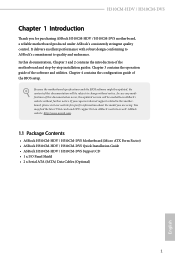
... documentation occur, the updated version will be available on ASRock's website as well. ASRock website http://www.asrock.com. 1.1 Package Contents • ASRock H310CM-HDV / H310CM-DVS Motherboard (Micro ATX Form Factor) • ASRock H310CM-HDV / H310CM-DVS Quick Installation Guide • ASRock H310CM-HDV / H310CM-DVS Support CD • 1 x I/O Panel Shield • 2 x Serial ATA (SATA) Data Cables (Optional) 1 English H310CM-HDV / H310CM-DVS Chapter 1 Introduction Thank you are using. It delivers excellent...
... documentation occur, the updated version will be available on ASRock's website as well. ASRock website http://www.asrock.com. 1.1 Package Contents • ASRock H310CM-HDV / H310CM-DVS Motherboard (Micro ATX Form Factor) • ASRock H310CM-HDV / H310CM-DVS Quick Installation Guide • ASRock H310CM-HDV / H310CM-DVS Support CD • 1 x I/O Panel Shield • 2 x Serial ATA (SATA) Data Cables (Optional) 1 English H310CM-HDV / H310CM-DVS Chapter 1 Introduction Thank you are using. It delivers excellent...
User Manual
Page 11
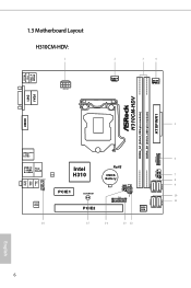
USB 2.0 T: USB1 B: USB2 PS2 Keyboard /Mouse HDMI1 1.3 Motherboard Layout H310CM-HDV: 1 ATX12V1 2 CPU_FAN1 3 4 CHA_FAN1/WP ATXPWR1 H310CM-HDV DDR4_A1 (64 bit, 288-pin module) DDR4_B1 (64 bit, 288-pin module) VGA1 DVI1 5 USB 3.1 Gen1 T: USB1 B: USB2 6 USB3_3_4 Top: LINE IN Center: FRONT Bottom: MIC IN USB 2.0 Top: T: USB3 RJ-45 B: USB4 LAN HD_AUDIO1 Intel H310 RoHS CMOS Battery USB_5_6 1 7 1 8 9 SATA3_2 SATA3_3 SPK_CI1 1 PLED PWRBTN PANEL1 1 HDLED RESET 1 PCIE1 CLRCMOS1 10 TPMS1 1 11 SATA3_0 SATA3_1 AUDIO CODEC PCIE2 BIOS ROM 16 15 14 13 12 English 6
USB 2.0 T: USB1 B: USB2 PS2 Keyboard /Mouse HDMI1 1.3 Motherboard Layout H310CM-HDV: 1 ATX12V1 2 CPU_FAN1 3 4 CHA_FAN1/WP ATXPWR1 H310CM-HDV DDR4_A1 (64 bit, 288-pin module) DDR4_B1 (64 bit, 288-pin module) VGA1 DVI1 5 USB 3.1 Gen1 T: USB1 B: USB2 6 USB3_3_4 Top: LINE IN Center: FRONT Bottom: MIC IN USB 2.0 Top: T: USB3 RJ-45 B: USB4 LAN HD_AUDIO1 Intel H310 RoHS CMOS Battery USB_5_6 1 7 1 8 9 SATA3_2 SATA3_3 SPK_CI1 1 PLED PWRBTN PANEL1 1 HDLED RESET 1 PCIE1 CLRCMOS1 10 TPMS1 1 11 SATA3_0 SATA3_1 AUDIO CODEC PCIE2 BIOS ROM 16 15 14 13 12 English 6
User Manual
Page 20
The cover must be placed if you wish to return the motherboard for after service. 15 English H310CM-HDV / H310CM-DVS Please save and replace the cover if the processor is removed.
The cover must be placed if you wish to return the motherboard for after service. 15 English H310CM-HDV / H310CM-DVS Please save and replace the cover if the processor is removed.
User Manual
Page 22
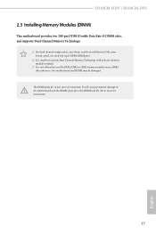
... or DDR3 memory module into the slot at incorrect orientation. 17 English For dual channel configuration, you force the DIMM into a DDR4 slot; H310CM-HDV / H310CM-DVS 2.3 Installing Memory Modules (DIMM) This motherboard provides two 288-pin DDR4 (Double Data Rate 4) DIMM slots, and supports Dual Channel Memory Technology. 1. It is not allowed to install...
... or DDR3 memory module into the slot at incorrect orientation. 17 English For dual channel configuration, you force the DIMM into a DDR4 slot; H310CM-HDV / H310CM-DVS 2.3 Installing Memory Modules (DIMM) This motherboard provides two 288-pin DDR4 (Double Data Rate 4) DIMM slots, and supports Dual Channel Memory Technology. 1. It is not allowed to install...
User Manual
Page 24
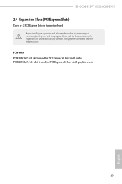
PCIe slots: PCIE1 (PCIe 2.0 x1 slot) is used for PCI Express x1 lane width cards. PCIE2 (PCIe 3.0 x16 slot) is unplugged. Before installing an expansion card, please make necessary hardware settings for the card before you start the installation. Please read the documentation of the expansion card and make sure that the power supply is switched off or the power cord is used for PCI Express x16 lane width graphics cards. 19 English H310CM-HDV / H310CM-DVS 2.4 Expansion Slots (PCI Express Slots) There are 2 PCI Express slots on the motherboard.
PCIe slots: PCIE1 (PCIe 2.0 x1 slot) is used for PCI Express x1 lane width cards. PCIE2 (PCIe 3.0 x16 slot) is unplugged. Before installing an expansion card, please make necessary hardware settings for the card before you start the installation. Please read the documentation of the expansion card and make sure that the power supply is switched off or the power cord is used for PCI Express x16 lane width graphics cards. 19 English H310CM-HDV / H310CM-DVS 2.4 Expansion Slots (PCI Express Slots) There are 2 PCI Express slots on the motherboard.
User Manual
Page 26
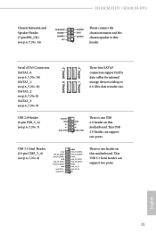
This USB 2.0 header can support two ports. H310CM-HDV / H310CM-DVS Chassis Intrusion and Speaker Header (7-pin SPK_CI1) (see p.6, 7, No. 14) SPEAKER DUMMY DUMMY +5V DUMMY GND SIGNAL 1 Please connect the .... 9) SATA3_0 SATA3_2 SATA3_1 SATA3_3 These four SATA3 connectors support SATA data cables for internal storage devices with up to this motherboard. USB_PWR GND P+ PUSB_PWR 1 There is one USB 2.0 header on this motherboard. USB 3.1 Gen1 Header (19-pin USB3_3_4) (see p.6, 7, No. 6) Vbus IntA_P2_SSRXIntA_P2_SSRX+ GND IntA_P2_SSTXIntA_P2_SSTX+ GND IntA_P2_DIntA_P2_D+ Vbus ...
This USB 2.0 header can support two ports. H310CM-HDV / H310CM-DVS Chassis Intrusion and Speaker Header (7-pin SPK_CI1) (see p.6, 7, No. 14) SPEAKER DUMMY DUMMY +5V DUMMY GND SIGNAL 1 Please connect the .... 9) SATA3_0 SATA3_2 SATA3_1 SATA3_3 These four SATA3 connectors support SATA data cables for internal storage devices with up to this motherboard. USB_PWR GND P+ PUSB_PWR 1 There is one USB 2.0 header on this motherboard. USB 3.1 Gen1 Header (19-pin USB3_3_4) (see p.6, 7, No. 6) Vbus IntA_P2_SSRXIntA_P2_SSRX+ GND IntA_P2_SSTXIntA_P2_SSTX+ GND IntA_P2_DIntA_P2_D+ Vbus ...
User Manual
Page 28
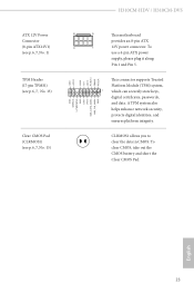
.... 13) Clear CMOS Pad (CLRMOS1) (see p.6, 7, No. 15) GND SERIRQ # S_PWRDWN # GN D LAD1 LAD2 SMB_DATA_MAIN SMB_CLK_MAIN GN D +3VS B LAD0 +3V LAD3 PCIRST # FRAM E PCICLK H310CM-HDV / H310CM-DVS 8 5 This motherboard provides an 8-pin ATX 4 1 12V power connector. GN D This connector supports Trusted Platform Module (TPM) system, 1 which can securely store keys, digital certificates, passwords, and...
.... 13) Clear CMOS Pad (CLRMOS1) (see p.6, 7, No. 15) GND SERIRQ # S_PWRDWN # GN D LAD1 LAD2 SMB_DATA_MAIN SMB_CLK_MAIN GN D +3VS B LAD0 +3V LAD3 PCIRST # FRAM E PCICLK H310CM-HDV / H310CM-DVS 8 5 This motherboard provides an 8-pin ATX 4 1 12V power connector. GN D This connector supports Trusted Platform Module (TPM) system, 1 which can securely store keys, digital certificates, passwords, and...
User Manual
Page 46
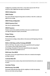
... Configuration DRAM Frequency Clock Select Auto for optimized settings. Command Rate (CR) The delay between a bank active command and issuing the precharge command. H310CM-HDV / H310CM-DVS Configure the current limit of clock cycles required between when a memory chip is selected, the motherboard will detect the memory module(s) inserted and assign the appropriate frequency automatically.
... Configuration DRAM Frequency Clock Select Auto for optimized settings. Command Rate (CR) The delay between a bank active command and issuing the precharge command. H310CM-HDV / H310CM-DVS Configure the current limit of clock cycles required between when a memory chip is selected, the motherboard will detect the memory module(s) inserted and assign the appropriate frequency automatically.
User Manual
Page 64
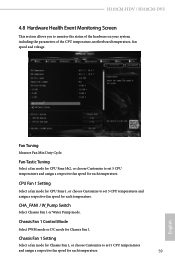
... for Chassis Fan 1, or choose Customize to set 5 CPU temperatures and assign a respective fan speed for each temperature. Fan Tuning Measure Fan Min Duty Cycle. H310CM-HDV / H310CM-DVS 4.8 Hardware Health Event Monitoring Screen This section allows you to set 5 CPU temperatures and assign a respective fan speed for each temperature. 59 English Fan-Tastic... a fan mode for CPU Fans 1&2, or choose Customize to monitor the status of the hardware on your system, including the parameters of the CPU temperature, motherboard temperature, fan speed and voltage.
... for Chassis Fan 1, or choose Customize to set 5 CPU temperatures and assign a respective fan speed for each temperature. Fan Tuning Measure Fan Min Duty Cycle. H310CM-HDV / H310CM-DVS 4.8 Hardware Health Event Monitoring Screen This section allows you to set 5 CPU temperatures and assign a respective fan speed for each temperature. 59 English Fan-Tastic... a fan mode for CPU Fans 1&2, or choose Customize to monitor the status of the hardware on your system, including the parameters of the CPU temperature, motherboard temperature, fan speed and voltage.
User Manual
Page 72
... 2.1077(a) Responsible Party Name: ASRock Incorporation Address: 13848 Magnolia Ave, Chino, CA91710 Phone/Fax No: +1-909-590-8308/+1-909-590-1026 hereby declares that may not cause harmful interference, and (2) this device must accept any interference received, including interference that the product Product Name : Motherboard Model Number : H310CM-HDV / H310CM-DVS Conforms to the following speci...
... 2.1077(a) Responsible Party Name: ASRock Incorporation Address: 13848 Magnolia Ave, Chino, CA91710 Phone/Fax No: +1-909-590-8308/+1-909-590-1026 hereby declares that may not cause harmful interference, and (2) this device must accept any interference received, including interference that the product Product Name : Motherboard Model Number : H310CM-HDV / H310CM-DVS Conforms to the following speci...
User Manual
Page 73
... for making this declaration: (Name, Surname) A.V.P (Position / Title) July 20, 2018 (Date) P/N: 15G062109000AK V1.0 EU Declaration of Conformity For the following equipment: Motherboard (Product Name) H310CM-HDV / H310CM-DVS / ASRock (Model Designation / Trade Name) ASRock Incorporation (Manufacturer Name) 2F., No.37, Sec. 2, Jhongyang S. Rd., Beitou District, Taipei City 112, Taiwan (R.O.C.) (Manufacturer Address) ڛEMC -Directive...
... for making this declaration: (Name, Surname) A.V.P (Position / Title) July 20, 2018 (Date) P/N: 15G062109000AK V1.0 EU Declaration of Conformity For the following equipment: Motherboard (Product Name) H310CM-HDV / H310CM-DVS / ASRock (Model Designation / Trade Name) ASRock Incorporation (Manufacturer Name) 2F., No.37, Sec. 2, Jhongyang S. Rd., Beitou District, Taipei City 112, Taiwan (R.O.C.) (Manufacturer Address) ڛEMC -Directive...


