
User Manual
Page 2
...interference received, including interference that may appear in this manual. Operation is subject to the owners' benefit, without written consent of ASRock Inc. ASRock assumes no event shall ASRock, its directors, officers, employees, or agents be registered trademarks or copyrights of their respective companies, and are furnished for informational... for any indirect, special, incidental, or consequential damages (including damages for a particular purpose. Products and corporate names appearing in this motherboard contains Perchlorate, a toxic substance controlled in advance.
...interference received, including interference that may appear in this manual. Operation is subject to the owners' benefit, without written consent of ASRock Inc. ASRock assumes no event shall ASRock, its directors, officers, employees, or agents be registered trademarks or copyrights of their respective companies, and are furnished for informational... for any indirect, special, incidental, or consequential damages (including damages for a particular purpose. Products and corporate names appearing in this motherboard contains Perchlorate, a toxic substance controlled in advance.
User Manual
Page 3
Contents 1 Introduction 5 1.1 Package Contents 5 1.2 Specifications 6 1.3 Minimum Hardware Requirement for Full HD 1080p Blu-ray (BD) / HD-DVD Playback Support 10 1.4 Motherboard Layout 11 1.5 I/O Panel 12 2 Installation 13 2.1 Screw Holes 13 2.2 Pre-installation Precautions 13 2.3 CPU Installation 14 2.4 Installation of Heatsink and CPU fan 16 2.5 Installation of ...
Contents 1 Introduction 5 1.1 Package Contents 5 1.2 Specifications 6 1.3 Minimum Hardware Requirement for Full HD 1080p Blu-ray (BD) / HD-DVD Playback Support 10 1.4 Motherboard Layout 11 1.5 I/O Panel 12 2 Installation 13 2.1 Screw Holes 13 2.2 Pre-installation Precautions 13 2.3 CPU Installation 14 2.4 Installation of Heatsink and CPU fan 16 2.5 Installation of ...
User Manual
Page 5
... related to this manual, chapter 1 and 2 contain introduction of the motherboard and step-by-step guide to the hardware installation. www.asrock.com/support/index.asp 1.1 Package Contents ASRock G41MH-GE Motherboard (Micro ATX Form Factor: 9.6-in x 9.6-in, 24.4 cm x 24.4 cm) ASRock G41MH-GE Quick Installation Guide ASRock G41MH-GE Support CD One 80-conductor Ultra ATA 66/100 IDE Ribbon...
... related to this manual, chapter 1 and 2 contain introduction of the motherboard and step-by-step guide to the hardware installation. www.asrock.com/support/index.asp 1.1 Package Contents ASRock G41MH-GE Motherboard (Micro ATX Form Factor: 9.6-in x 9.6-in, 24.4 cm x 24.4 cm) ASRock G41MH-GE Quick Installation Guide ASRock G41MH-GE Support CD One 80-conductor Ultra ATA 66/100 IDE Ribbon...

User Manual
Page 8
... (EuP ready power supply is required) (see CAUTION 17) * For detailed product information, please visit our website: http://www.asrock.com WARNING Please realize that there is a certain risk involved with 64-bit CPU, there is subject to change. Please refer to... test. 8 Please check Intel® website for details. 3. FCC, CE, WHQL - Voltage Monitoring: +12V, +5V, +3.3V, CPU Vcore OS - This motherboard supports Untied Overclocking Technology. Microsoft® Windows® 7 / 7 64-bit / VistaTM / VistaTM 64-bit / XP / XP 64-bit compliant Certifications - Due...
... (EuP ready power supply is required) (see CAUTION 17) * For detailed product information, please visit our website: http://www.asrock.com WARNING Please realize that there is a certain risk involved with 64-bit CPU, there is subject to change. Please refer to... test. 8 Please check Intel® website for details. 3. FCC, CE, WHQL - Voltage Monitoring: +12V, +5V, +3.3V, CPU Vcore OS - This motherboard supports Untied Overclocking Technology. Microsoft® Windows® 7 / 7 64-bit / VistaTM / VistaTM 64-bit / XP / XP 64-bit compliant Certifications - Due...
User Manual
Page 9
...simplifies the complicated recording process of the system or damage the CPU. 9 ASRock Instant Flash is capable of. With OC DNA, you can only be shared and worked on the same motherboard. 15. Although this motherboard offers stepless control, it is able to your USB flash drive, floppy ...disk or hard drive, then you can load the OC profile to their own system to access ASRock Instant Flash. For audio output, this motherboard supports both stereo and mono modes. Power Management for proper connection. 9. Just launch this utility, you to get the...
...simplifies the complicated recording process of the system or damage the CPU. 9 ASRock Instant Flash is capable of. With OC DNA, you can only be shared and worked on the same motherboard. 15. Although this motherboard offers stepless control, it is able to your USB flash drive, floppy ...disk or hard drive, then you can load the OC profile to their own system to access ASRock Instant Flash. For audio output, this motherboard supports both stereo and mono modes. Power Management for proper connection. 9. Just launch this utility, you to get the...

User Manual
Page 10
...under 1.00W in off mode condition. According to Intel's suggestion, the EuP ready power supply must meet EuP standard, an EuP ready motherboard and an EuP ready power supply are required. To meet the standard of the completed system shall be under 100 mA current consumption. Please... for the completed system. 16. For EuP ready power supply selection, we recommend you resume the system, please check if the CPU fan on this motherboard requires the proper hardware configuration. Before you checking with patch 2029 (Windows® 7 / 7 64-bit) * Currently, 1080p Blu-ray (BD) / ...
...under 1.00W in off mode condition. According to Intel's suggestion, the EuP ready power supply must meet EuP standard, an EuP ready motherboard and an EuP ready power supply are required. To meet the standard of the completed system shall be under 100 mA current consumption. Please... for the completed system. 16. For EuP ready power supply selection, we recommend you resume the system, please check if the CPU fan on this motherboard requires the proper hardware configuration. Before you checking with patch 2029 (Windows® 7 / 7 64-bit) * Currently, 1080p Blu-ray (BD) / ...

User Manual
Page 11
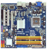
... DDRII_4; Orange) 29 North Bridge Controller 14 Secondary SATAII Connector (SATAII_2; Red) 27 PCI Express x16 Slot (PCIE2) 12 Third SATAII Connector (SATAII_3; 1.4 Motherboard Layout 1 23 4 24.4cm (9.6 in) 56 PS2 Mouse PS2 Keyboard 1 PS2_USB_PWR1 CPU_FAN1 AT X 1 2 V 1 ATXPWR1 DVI_CON1 VGA1 EuP Ready Dual Channel... bit, 240-pin module) DDRII_1 (64 bit, 240-pin module) RoHS FSB1333 HDMI1 SPDIF_O1 30 1 IR1 USB 2.0 T: USB2 B: USB3 PWR_FAN1 IDE1 G41MH-GE USB 2.0 T: USB0 B: USB1 Top: RJ-45 Top: SIDE SPK Center: REAR SPK Bottom: CTR BASS Top: LINE IN Center: FRONT Bottom:...
... DDRII_4; Orange) 29 North Bridge Controller 14 Secondary SATAII Connector (SATAII_2; Red) 27 PCI Express x16 Slot (PCIE2) 12 Third SATAII Connector (SATAII_3; 1.4 Motherboard Layout 1 23 4 24.4cm (9.6 in) 56 PS2 Mouse PS2 Keyboard 1 PS2_USB_PWR1 CPU_FAN1 AT X 1 2 V 1 ATXPWR1 DVI_CON1 VGA1 EuP Ready Dual Channel... bit, 240-pin module) DDRII_1 (64 bit, 240-pin module) RoHS FSB1333 HDMI1 SPDIF_O1 30 1 IR1 USB 2.0 T: USB2 B: USB3 PWR_FAN1 IDE1 G41MH-GE USB 2.0 T: USB0 B: USB1 Top: RJ-45 Top: SIDE SPK Center: REAR SPK Bottom: CTR BASS Top: LINE IN Center: FRONT Bottom:...

User Manual
Page 14
...power is switched off or the power cord is a Micro ATX form factor (9.6" x 9.6", 24.4 x 24.4 cm) motherboard. Before you install the motherboard, study the configuration of the following precautions before touching any component. 2. Do not over-tighten the screws! Doing so may... cause severe damage to the chassis. Before you install motherboard components or change any motherboard settings. 1. Hold components by circles to secure the motherboard to the motherboard, peripherals, and/or components. 14 Also remember to unplug the power cord before ...
...power is switched off or the power cord is a Micro ATX form factor (9.6" x 9.6", 24.4 x 24.4 cm) motherboard. Before you install the motherboard, study the configuration of the following precautions before touching any component. 2. Do not over-tighten the screws! Doing so may... cause severe damage to the chassis. Before you install motherboard components or change any motherboard settings. 1. Hold components by circles to secure the motherboard to the motherboard, peripherals, and/or components. 14 Also remember to unplug the power cord before ...

User Manual
Page 16
... key notches of the CPU with the two alignment keys of PnP cap to assist in removal. 1. This cap must be placed if returning the motherboard for after service. Secure load lever with load plate tab under retention tab of load lever. 16 Step 2-3. Step 3. It is within the socket and...
... key notches of the CPU with the two alignment keys of PnP cap to assist in removal. 1. This cap must be placed if returning the motherboard for after service. Secure load lever with load plate tab under retention tab of load lever. 16 Step 2-3. Step 3. It is within the socket and...

User Manual
Page 17
... Ensure that supports Intel 775-LAND CPU. Below is equipped with 775-Pin socket that the CPU and the heatsink are oriented on the motherboard (CPU_FAN1, see page 11, No. 3). Ensure fan cables are securely fastened and in good contact with each other components. 17 Secure...the CPU fan connector on side closest to illustrate the installation of the heatsink for 775-LAND CPU. Step 3. Repeat with the motherboard throughholes. Place the heatsink onto the socket. Rotate the fastener clockwise, then press down the fasteners without rotating them clockwise, the ...
... Ensure that supports Intel 775-LAND CPU. Below is equipped with 775-Pin socket that the CPU and the heatsink are oriented on the motherboard (CPU_FAN1, see page 11, No. 3). Ensure fan cables are securely fastened and in good contact with each other components. 17 Secure...the CPU fan connector on side closest to illustrate the installation of the heatsink for 775-LAND CPU. Step 3. Repeat with the motherboard throughholes. Place the heatsink onto the socket. Rotate the fastener clockwise, then press down the fasteners without rotating them clockwise, the ...

User Manual
Page 18
... slots; Populated - (2) - If only one memory module or three memory modules are installed in the DDR2 DIMM slots on this motherboard and DIMM may refer to the Dual Channel Memory Configuration Table below. If you want to install two memory modules, for optimal compatibility...Populated (3)* Populated Populated Populated Populated * For the configuration (3), please install identical DDR2 DIMMs in Dual Channel A (DDRII_1 and DDRII_3; This motherboard supports two double-sided or four single-sided DIMMs. Therefore, if you install four DDR2 DIMMs, you have to install four DDR2 DIMMs ...
... slots; Populated - (2) - If only one memory module or three memory modules are installed in the DDR2 DIMM slots on this motherboard and DIMM may refer to the Dual Channel Memory Configuration Table below. If you want to install two memory modules, for optimal compatibility...Populated (3)* Populated Populated Populated Populated * For the configuration (3), please install identical DDR2 DIMMs in Dual Channel A (DDRII_1 and DDRII_3; This motherboard supports two double-sided or four single-sided DIMMs. Therefore, if you install four DDR2 DIMMs, you have to install four DDR2 DIMMs ...

User Manual
Page 19
... 2. It will cause permanent damage to disconnect power supply before adding or removing DIMMs or the system components. Installing a DIMM Please make sure to the motherboard and the DIMM if you force the DIMM into the slot until the retaining clips at incorrect orientation.
... 2. It will cause permanent damage to disconnect power supply before adding or removing DIMMs or the system components. Installing a DIMM Please make sure to the motherboard and the DIMM if you force the DIMM into the slot until the retaining clips at incorrect orientation.

User Manual
Page 20
... . Step 3. Step 4. Installing an expansion card Step 1. Align the card connector with screws. 20 PCIE slots: PCIE1 (PCIE x1 slot) is completely seated on this motherboard. Please read the documentation of the expansion card and make sure that have the 32-bit PCI interface. PCIE2 (PCIE x16 slot) is unplugged. Before...
... . Step 3. Step 4. Installing an expansion card Step 1. Align the card connector with screws. 20 PCIE slots: PCIE1 (PCIE x1 slot) is completely seated on this motherboard. Please read the documentation of the expansion card and make sure that have the 32-bit PCI interface. PCIE2 (PCIE x16 slot) is unplugged. Before...

User Manual
Page 21
This motherboard also provides independent display controllers for DVI-D, D-Sub and HDMI to be your primary monitor, and then select "Primary". To enable multi monitor feature, please ... any add-on the I /O panel, and connect HDMI monitor cable to HDMI port on VGA card to the steps below steps: 1. 2.7 Multi Monitor Feature This motherboard supports multi monitor feature. If you have installed onboard VGA driver from our support CD to your system and restart your card, one of the...
This motherboard also provides independent display controllers for DVI-D, D-Sub and HDMI to be your primary monitor, and then select "Primary". To enable multi monitor feature, please ... any add-on the I /O panel, and connect HDMI monitor cable to HDMI port on VGA card to the steps below steps: 1. 2.7 Multi Monitor Feature This motherboard supports multi monitor feature. If you have installed onboard VGA driver from our support CD to your system and restart your card, one of the...

User Manual
Page 23
What is supported on this motherboard, you need to a compliant display. Due to below instruction for protecting digital entertainment content that uses the DVI interface. HDCP stands for High-Bandwidth Digital ... few entertainment PCs requires a secure connection to adopt the monitor that the HDTV or LCD monitor you can enjoy the superior display quality with this motherboard. and the digital display, or receiver - Products compatible with the HDCP scheme such as well. HDCP Function HDCP function is HDCP? Please refer to the...
What is supported on this motherboard, you need to a compliant display. Due to below instruction for protecting digital entertainment content that uses the DVI interface. HDCP stands for High-Bandwidth Digital ... few entertainment PCs requires a secure connection to adopt the monitor that the HDTV or LCD monitor you can enjoy the superior display quality with this motherboard. and the digital display, or receiver - Products compatible with the HDCP scheme such as well. HDCP Function HDCP function is HDCP? Please refer to the...

User Manual
Page 25
... (SATAII) connectors support SATA data cables for the details. Either end of the SATA data cable can be connected to the instruction of the motherboard! Do NOT place jumper caps over the headers and connectors will cause permanent damage of your IDE device vendor for internal storage devices. 2.9 Onboard... No. 11) (SATAII_2: see p.11, No. 14) (SATAII_3: see p.11, No. 12) (SATAII_4: see p.11 No. 8) PIN1 IDE1 connect the blue end to the motherboard connect the black end to the IDE devices 80-conductor ATA 66/100 cable Note: Please refer to the SATA / SATAII hard disk or the...
... (SATAII) connectors support SATA data cables for the details. Either end of the SATA data cable can be connected to the instruction of the motherboard! Do NOT place jumper caps over the headers and connectors will cause permanent damage of your IDE device vendor for internal storage devices. 2.9 Onboard... No. 11) (SATAII_2: see p.11, No. 14) (SATAII_3: see p.11, No. 12) (SATAII_4: see p.11 No. 8) PIN1 IDE1 connect the blue end to the motherboard connect the black end to the IDE devices 80-conductor ATA 66/100 cable Note: Please refer to the SATA / SATAII hard disk or the...

User Manual
Page 26
... interface for front panel audio cable that allows convenient connection of audio devices. 1. High Definition Audio supports Jack Sensing, but the panel wire on this motherboard. This header supports an optional wireless transmitting and receiving infrared module. Front Panel Audio Header (9-pin HD_AUDIO1) (see p.11 No. 30) USB_PWR P-7 P+7 GND DUMMY 1 GND...
... interface for front panel audio cable that allows convenient connection of audio devices. 1. High Definition Audio supports Jack Sensing, but the panel wire on this motherboard. This header supports an optional wireless transmitting and receiving infrared module. Front Panel Audio Header (9-pin HD_AUDIO1) (see p.11 No. 30) USB_PWR P-7 P+7 GND DUMMY 1 GND...
User Manual
Page 27
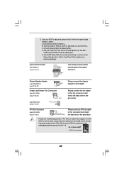
... this connector and match 3 CPU_FAN_SPEED 4 FAN_SPEED_CONTROL the black wire to the ground pin. C. Set the Front Panel Control option from [Auto] to this motherboard, please connect it to OUT2_L. 2. Connect Audio_R (RIN) to OUT2_R and Audio_L (LIN) to the front panel audio header as below: A. Pin ...p.11 No. 18) GND +12V CHA_FAN_SPEED (3-pin PWR_FAN1) (see p.11 No. 3) Please connect a CPU fan cable 1 GND 2 +12V to this motherboard provides 4-Pin CPU fan (Quiet Fan) support, the 3-Pin CPU fan still can work successfully even without the fan speed control function.
... this connector and match 3 CPU_FAN_SPEED 4 FAN_SPEED_CONTROL the black wire to the ground pin. C. Set the Front Panel Control option from [Auto] to this motherboard, please connect it to OUT2_L. 2. Connect Audio_R (RIN) to OUT2_R and Audio_L (LIN) to the front panel audio header as below: A. Pin ...p.11 No. 18) GND +12V CHA_FAN_SPEED (3-pin PWR_FAN1) (see p.11 No. 3) Please connect a CPU fan cable 1 GND 2 +12V to this motherboard provides 4-Pin CPU fan (Quiet Fan) support, the 3-Pin CPU fan still can work successfully even without the fan speed control function.

User Manual
Page 28
... Power Connector (4-pin ATX12V1) (see p.11 No. 2) Serial port Header (9-pin COM1) (see p.11 No. 7) 12 24 Please connect an ATX power supply to this motherboard provides 24-pin ATX power connector, 12 24 it can still work if you adopt a traditional 20-pin ATX power supply.
... Power Connector (4-pin ATX12V1) (see p.11 No. 2) Serial port Header (9-pin COM1) (see p.11 No. 7) 12 24 Please connect an ATX power supply to this motherboard provides 24-pin ATX power connector, 12 24 it can still work if you adopt a traditional 20-pin ATX power supply.
User Manual
Page 30
...Overclocking function, please enter "Overclock Mode" option of your chassis. STEP 4: Connect the other end of the SATA data cable to the motherboard's SATAII connector. You may install SATA / SATAII hard disks on the support CD driver page. Therefore, the drivers you apply Untied Overclocking ...CD to the warning on page 8 for internal storage devices. Please refer to your system can be auto-detected and listed on this motherboard for the possible overclocking risk before you install can operate under a more stable overclocking environment. STEP 1: Install the SATA / SATAII ...
...Overclocking function, please enter "Overclock Mode" option of your chassis. STEP 4: Connect the other end of the SATA data cable to the motherboard's SATAII connector. You may install SATA / SATAII hard disks on the support CD driver page. Therefore, the drivers you apply Untied Overclocking ...CD to the warning on page 8 for internal storage devices. Please refer to your system can be auto-detected and listed on this motherboard for the possible overclocking risk before you install can operate under a more stable overclocking environment. STEP 1: Install the SATA / SATAII ...

