
User Manual
Page 3
... Guide 27 2.11 Serial ATA (SATA) / Serial ATAII (SATAII) Hard Disks Installation 28 2.12 Driver Installation Guide 28 2.13 Untied Overclocking Technology 28 3 BIOS SETUP UTILITY 29 3.1 Introduction 29 3.1.1 BIOS Menu Bar 29 3.1.2 Navigation Keys 30 3.2 Main Screen 30 3.3 OC Tweaker Screen 31 3.4 Advanced Screen 35 3.4.1 CPU Configuration 36 3.4.2 Chipset Configuration 38...
... Guide 27 2.11 Serial ATA (SATA) / Serial ATAII (SATAII) Hard Disks Installation 28 2.12 Driver Installation Guide 28 2.13 Untied Overclocking Technology 28 3 BIOS SETUP UTILITY 29 3.1 Introduction 29 3.1.1 BIOS Menu Bar 29 3.1.2 Navigation Keys 30 3.2 Main Screen 30 3.3 OC Tweaker Screen 31 3.4 Advanced Screen 35 3.4.1 CPU Configuration 36 3.4.2 Chipset Configuration 38...

User Manual
Page 5
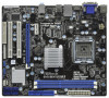
.... Because the motherboard specifications and the BIOS software might be updated, the content of this manual, chapter 1 and 2 contain introduction of this motherboard, please visit our website for purchasing ASRock G41MH/USB3 motherboard, a reliable motherboard produced under ASRock's consistently stringent quality control. www.asrock.com/support/index.asp 1.1 Package Contents ASRock G41MH/USB3 Motherboard (Micro ATX Form Factor: 9.6-in...
.... Because the motherboard specifications and the BIOS software might be updated, the content of this manual, chapter 1 and 2 contain introduction of this motherboard, please visit our website for purchasing ASRock G41MH/USB3 motherboard, a reliable motherboard produced under ASRock's consistently stringent quality control. www.asrock.com/support/index.asp 1.1 Package Contents ASRock G41MH/USB3 Motherboard (Micro ATX Form Factor: 9.6-in...
User Manual
Page 7
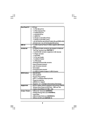
... 2 x IDE devices) - 1 x Floppy connector - 1 x IR header - 1 x Print port header - 1 x COM port header - 1 x TPM header - ASRock OC DNA (see CAUTION 10) - Intelligent Energy Saver (see CAUTION 8) - Trial) - Instant Boot - HD Audio Jack: Line in header - Front panel audio connector - ... x USB 2.0 headers (support 4 USB 2.0 ports) - 8Mb AMI BIOS - ACPI 1.1 Compliance Wake Up Events - T. (Intelligent Overclocking Technology) - Creative Sound Blaster X-Fi MB - Supports "Plug and Play" - ASRock OC Tuner (see CAUTION 9) - CPU/Chassis/Power FAN connector - 24...
... 2 x IDE devices) - 1 x Floppy connector - 1 x IR header - 1 x Print port header - 1 x COM port header - 1 x TPM header - ASRock OC DNA (see CAUTION 10) - Intelligent Energy Saver (see CAUTION 8) - Trial) - Instant Boot - HD Audio Jack: Line in header - Front panel audio connector - ... x USB 2.0 headers (support 4 USB 2.0 ports) - 8Mb AMI BIOS - ACPI 1.1 Compliance Wake Up Events - T. (Intelligent Overclocking Technology) - Creative Sound Blaster X-Fi MB - Supports "Plug and Play" - ASRock OC Tuner (see CAUTION 9) - CPU/Chassis/Power FAN connector - 24...
User Manual
Page 8
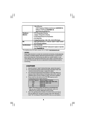
...DDR3 1333 1066 DDR3 800, DDR3 1066 800 DDR3 800 533 DDR3 800 * DDR3 1333 memory modules will operate in the BIOS, applying Untied Overclocking Technology, or using the thirdparty overclocking tools. About the setting of memory modules on page 17 for ...supply is required) (see CAUTION 14) * For detailed product information, please visit our website: http://www.asrock.com WARNING Please realize that there is no such limitation. 8 - Hybrid Booster: - ASRock U-COP (see CAUTION 12) - Boot Failure Guard (B.F.G.) Hardware - CAUTION! 1. This motherboard supports Dual ...
...DDR3 1333 1066 DDR3 800, DDR3 1066 800 DDR3 800 533 DDR3 800 * DDR3 1333 memory modules will operate in the BIOS, applying Untied Overclocking Technology, or using the thirdparty overclocking tools. About the setting of memory modules on page 17 for ...supply is required) (see CAUTION 14) * For detailed product information, please visit our website: http://www.asrock.com WARNING Please realize that there is no such limitation. 8 - Hybrid Booster: - ASRock U-COP (see CAUTION 12) - Boot Failure Guard (B.F.G.) Hardware - CAUTION! 1. This motherboard supports Dual ...

User Manual
Page 9
... your hardware devices to change. While CPU overheat is a BIOS flash utility embedded in a few clicks without preparing an additional floppy diskette or other complicated flash utility. Please visit our website for the operation procedures of ASRock OC Tuner. Please visit our website for the operation procedures ...can also connect SATA hard disk to access ASRock Instant Flash. With OC DNA, you resume the system, please check if the CPU fan on the same motherboard. 12. You can press key during the POST or press key to BIOS setup menu to SATAII connector directly. 8. ...
... your hardware devices to change. While CPU overheat is a BIOS flash utility embedded in a few clicks without preparing an additional floppy diskette or other complicated flash utility. Please visit our website for the operation procedures of ASRock OC Tuner. Please visit our website for the operation procedures ...can also connect SATA hard disk to access ASRock Instant Flash. With OC DNA, you resume the system, please check if the CPU fan on the same motherboard. 12. You can press key during the POST or press key to BIOS setup menu to SATAII connector directly. 8. ...

User Manual
Page 11
... Floppy Connector (FLOPPY1) 8 Chassis Fan Connector (CHA_FAN1) 25 Serial Port Connector (COM1) 9 IDE1 Connector (IDE1, Blue) 26 PCI Slots (PCI1- 2) 10 BIOS SPI Chip 27 PCI Express x16 Slot (PCIE2) 11 South Bridge Controller 28 Internal Audio Connector: CD1 (Black) 12 Clear CMOS Jumper (CLRCMOS1) 29 PCI..., 240-pin module) HDMI1 32 USB 2.0 T: USB0 B: USB1 Top: RJ-45 PWR_FAN1 31 7 24.4cm (9.6 in) G41MH/USB3 1 Designed in Taipei ErP/EuP Ready USB 2.0: USB2 USB 3.0: USB3 LAN PHY 30 Intel G41 Chipset CHA_FAN1 8 TPM1 1 29 28 27 26 Top: LINE IN Center: FRONT Bottom: MIC IN...
... Floppy Connector (FLOPPY1) 8 Chassis Fan Connector (CHA_FAN1) 25 Serial Port Connector (COM1) 9 IDE1 Connector (IDE1, Blue) 26 PCI Slots (PCI1- 2) 10 BIOS SPI Chip 27 PCI Express x16 Slot (PCIE2) 11 South Bridge Controller 28 Internal Audio Connector: CD1 (Black) 12 Clear CMOS Jumper (CLRCMOS1) 29 PCI..., 240-pin module) HDMI1 32 USB 2.0 T: USB0 B: USB1 Top: RJ-45 PWR_FAN1 31 7 24.4cm (9.6 in) G41MH/USB3 1 Designed in Taipei ErP/EuP Ready USB 2.0: USB2 USB 3.0: USB3 LAN PHY 30 Intel G41 Chipset CHA_FAN1 8 TPM1 1 29 28 27 26 Top: LINE IN Center: FRONT Bottom: MIC IN...
User Manual
Page 28
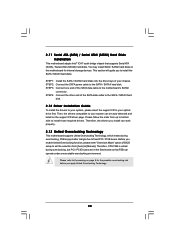
... drive first. Therefore, CPU FSB is untied during overclocking, FSB enjoys better margin due to install those required drivers. STEP 4: Connect the other end of BIOS setup to set the selection from up to bottom side to fixed PCI / PCIE buses. Before you to [Manual]. Please follow the order from [Auto...
... drive first. Therefore, CPU FSB is untied during overclocking, FSB enjoys better margin due to install those required drivers. STEP 4: Connect the other end of BIOS setup to set the selection from up to bottom side to fixed PCI / PCIE buses. Before you to [Manual]. Please follow the order from [Auto...

User Manual
Page 29
... system chassis. If you wish to locate and load the Operating System Security To set up the computer. Chapter 3 BIOS SETUP UTILITY 3.1 Introduction This section explains how to use the BIOS SETUP UTILITY to get into the sub screen. 29 Please press or during the Power-On-Self-Test (POST) to... enter the BIOS SETUP UTILITY, otherwise, POST will continue with the following BIOS setup screens and descriptions are for reference purpose only, and they may not exactly match what you start up the ...
... system chassis. If you wish to locate and load the Operating System Security To set up the computer. Chapter 3 BIOS SETUP UTILITY 3.1 Introduction This section explains how to use the BIOS SETUP UTILITY to get into the sub screen. 29 Please press or during the Power-On-Self-Test (POST) to... enter the BIOS SETUP UTILITY, otherwise, POST will continue with the following BIOS setup screens and descriptions are for reference purpose only, and they may not exactly match what you start up the ...

User Manual
Page 30
... description of each navigation key. 3.1.2 Navigation Keys Please check the following table for all the settings To save changes and exit the BIOS SETUP UTILITY To jump to the Exit Screen or exit the current screen 3.2 Main Screen When you enter the... UTILITY Main OC Tweaker Advanced H/W Monitor Boot Security Exit System Overview System Time System Date [14:00:09] [Thu 05/13/2010] BIOS Version : G41MH/USB3 P1.00 Processor Type : Intel (R) Pentium (R) Dual CPU E2220 @ 2.40GHz (64bit) Processor Speed : 2400MHz Microcode Update : 6FB/A3 Cache Size : 1024KB Total Memory DDR3_A1...
... description of each navigation key. 3.1.2 Navigation Keys Please check the following table for all the settings To save changes and exit the BIOS SETUP UTILITY To jump to the Exit Screen or exit the current screen 3.2 Main Screen When you enter the... UTILITY Main OC Tweaker Advanced H/W Monitor Boot Security Exit System Overview System Time System Date [14:00:09] [Thu 05/13/2010] BIOS Version : G41MH/USB3 P1.00 Processor Type : Intel (R) Pentium (R) Dual CPU E2220 @ 2.40GHz (64bit) Processor Speed : 2400MHz Microcode Update : 6FB/A3 Cache Size : 1024KB Total Memory DDR3_A1...

User Manual
Page 31
... your CPU and motherboard. Please refer to your own risk and expense. Please note that overclocing may select [400MHz DDR3_800], [533MHz DDR3_1066] or [667MHz DDR3_1333]. BIOS SETUP UTILITY Main OC Tweaker Advanced H/W Monitor Boot Security Exit OC Tweaker Settings Load CPU EZ OC Setting [Disabled] DRAM Frequency DRAM Command Rate DRAM...
... your CPU and motherboard. Please refer to your own risk and expense. Please note that overclocing may select [400MHz DDR3_800], [533MHz DDR3_1066] or [667MHz DDR3_1333]. BIOS SETUP UTILITY Main OC Tweaker Advanced H/W Monitor Boot Security Exit OC Tweaker Settings Load CPU EZ OC Setting [Disabled] DRAM Frequency DRAM Command Rate DRAM...

User Manual
Page 32
The default value is [Auto]. Max: 10. Max: 10. Min: 15. The default value is [Auto]. Max: 15. DRAM Timing Configuration BIOS SETUP UTILITY OC Tweaker DRAM Timing Control DRAM tCL 6 DRAM tRCD 6 DRAM tRP 6 DRAM tRAS 15 DRAM tRFC 44 DRAM tWR 6 DRAM tWTR 4 DRAM tRRD 3 ...
The default value is [Auto]. Max: 10. Max: 10. Min: 15. The default value is [Auto]. Max: 15. DRAM Timing Configuration BIOS SETUP UTILITY OC Tweaker DRAM Timing Control DRAM tCL 6 DRAM tRCD 6 DRAM tRP 6 DRAM tRAS 15 DRAM tRFC 44 DRAM tWR 6 DRAM tWTR 4 DRAM tRRD 3 ...

User Manual
Page 35
...Sub Screen F1 General Help F9 Load Defaults F10 Save and Exit ESC Exit v02.54 (C) Copyright 1985-2005, American Megatrends, Inc. BIOS SETUP UTILITY Main OC Tweaker Advanced H/W Monitor Boot Security Exit Advanced Settings Options for CPU WARNING : Setting wrong values in this section,... Configuration, and USB Configuration. CPU Configuration Chipset Configuration ACPI Configuration Storage Configuration PCIPnP Configuration Floppy Configuration SuperIO Configuration USB Configuration BIOS Update Utility ASRock Instant Flash Select Screen Select Item Enter Go to malfunction. 35
...Sub Screen F1 General Help F9 Load Defaults F10 Save and Exit ESC Exit v02.54 (C) Copyright 1985-2005, American Megatrends, Inc. BIOS SETUP UTILITY Main OC Tweaker Advanced H/W Monitor Boot Security Exit Advanced Settings Options for CPU WARNING : Setting wrong values in this section,... Configuration, and USB Configuration. CPU Configuration Chipset Configuration ACPI Configuration Storage Configuration PCIPnP Configuration Floppy Configuration SuperIO Configuration USB Configuration BIOS Update Utility ASRock Instant Flash Select Screen Select Item Enter Go to malfunction. 35
User Manual
Page 36
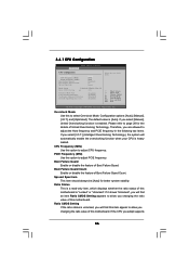
... in the following two items. If you adopt supports 36 Boot Failure Guard Enable or disable the feature of Boot Failure Guard Count. 3.4.1 CPU Configuration BIOS SETUP UTILITY Advanced CPU Configuration Overclock Mode CPU Frequency (MHz) PCIE Frequency (MHz) Boot Failure Guard Boot Failure Guard Count Spread Spectrum [Auto] [200] [100...
... in the following two items. If you adopt supports 36 Boot Failure Guard Enable or disable the feature of Boot Failure Guard Count. 3.4.1 CPU Configuration BIOS SETUP UTILITY Advanced CPU Configuration Overclock Mode CPU Frequency (MHz) PCIE Frequency (MHz) Boot Failure Guard Boot Failure Guard Count Spread Spectrum [Auto] [200] [100...

User Manual
Page 38
...G0 (Data). Max: 15. Min: 1. Max: 63. The default value is [Auto]. Max: 15. DRAM RCOMP and tRD Configuration BIOS SETUP UTILITY Advanced DRAM RCOMP STRENGTH Settings DRAM CH0 RCOMP STRENGTH Info : 54-0-11-6-6-6-6 DRAM CH0 RCOMP ODT DRAM CH0 G0 (Data) ...]. 38 Min: 1. DRAM CH0 RCOMP ODT This controls the number of DRAM CH0 G2 (Control1). Max: 15. 3.4.2 Chipset Configuration BIOS SETUP UTILITY Advanced Chipset Settings DRAM RCOMP and tRD Configuration DRAM DLL SKEW Configuration Fixed Mode Operation [Enabled] Intelligent Energy Saver Primary Graphics Adapter...
...G0 (Data). Max: 15. Min: 1. Max: 63. The default value is [Auto]. Max: 15. DRAM RCOMP and tRD Configuration BIOS SETUP UTILITY Advanced DRAM RCOMP STRENGTH Settings DRAM CH0 RCOMP STRENGTH Info : 54-0-11-6-6-6-6 DRAM CH0 RCOMP ODT DRAM CH0 G0 (Data) ...]. 38 Min: 1. DRAM CH0 RCOMP ODT This controls the number of DRAM CH0 G2 (Control1). Max: 15. 3.4.2 Chipset Configuration BIOS SETUP UTILITY Advanced Chipset Settings DRAM RCOMP and tRD Configuration DRAM DLL SKEW Configuration Fixed Mode Operation [Enabled] Intelligent Energy Saver Primary Graphics Adapter...

User Manual
Page 40
... controls the number of DRAM CH0 CTRL0 SKEW. DRAM CH1 CLKSET0 SKEW This controls the number of DRAM CH1 CLKSET0 SKEW. DRAM DLL SKEW Configuration BIOS SETUP UTILITY Advanced DRAM DLL SKEW Settings DRAM CH0 CLKSET0 SKEW Info:0-0-0-0-0-0 DRAM CH0 CLKSET0 SKEW [Auto] DRAM CH0 CLKSET1 SKEW Info:0-0-0-0-0-0 DRAM CH0 CLKSET1...
... controls the number of DRAM CH0 CTRL0 SKEW. DRAM CH1 CLKSET0 SKEW This controls the number of DRAM CH1 CLKSET0 SKEW. DRAM DLL SKEW Configuration BIOS SETUP UTILITY Advanced DRAM DLL SKEW Settings DRAM CH0 CLKSET0 SKEW Info:0-0-0-0-0-0 DRAM CH0 CLKSET0 SKEW [Auto] DRAM CH0 CLKSET1 SKEW Info:0-0-0-0-0-0 DRAM CH0 CLKSET1...

User Manual
Page 41
... controls the number of compressed video buffer and is [Disabled]. DRAM CH1 CTRL2 SKEW This controls the number of DRAM CH1 CTRL0 SKEW. Besides the BIOS option, you to set this function. The default value is [Enabled]. Configuration options: [Enabled] and [Disabled]. The default value is hardware-based 128-bit AES...
... controls the number of compressed video buffer and is [Disabled]. DRAM CH1 CTRL2 SKEW This controls the number of DRAM CH1 CTRL0 SKEW. Besides the BIOS option, you to set this function. The default value is [Enabled]. Configuration options: [Enabled] and [Disabled]. The default value is hardware-based 128-bit AES...

User Manual
Page 43
... after an unexpected AC/Power loss. PCI Devices Power On Use this item to RAM Use this feature if the OS supports it. 3.4.3 ACPI Configuration BIOS SETUP UTILITY Advanced ACPI Configuration Suspend To RAM Restore on the system from the power-soft-off when the power recovers. If [Power Off] is...
... after an unexpected AC/Power loss. PCI Devices Power On Use this item to RAM Use this feature if the OS supports it. 3.4.3 ACPI Configuration BIOS SETUP UTILITY Advanced ACPI Configuration Suspend To RAM Restore on the system from the power-soft-off when the power recovers. If [Power Off] is...

User Manual
Page 44
... It allows you install legacy OS (Windows® NT). When [Compatible] is set to [IDE 1, SATA 2, SATA 4], then SATAII_1, SATAII_3 will not work . 3.4.4 Storage Configuration BIOS SETUP UTILITY Advanced Storage Configuration ATA/IDE Configuration SATAII_1 SATAII_2 SATAII_3 SATAII_4 IDE1 Master IDE1 Slave [Enhanced] [Hard Disk] [Not Detected] [Not Detected] [Not Detected...
... It allows you install legacy OS (Windows® NT). When [Compatible] is set to [IDE 1, SATA 2, SATA 4], then SATAII_1, SATAII_3 will not work . 3.4.4 Storage Configuration BIOS SETUP UTILITY Advanced Storage Configuration ATA/IDE Configuration SATAII_1 SATAII_2 SATAII_3 SATAII_4 IDE1 Master IDE1 Slave [Enhanced] [Hard Disk] [Not Detected] [Not Detected] [Not Detected...

User Manual
Page 45
... hard disk timing. 45 TYPE Use this item to partition and format the new IDE hard disk drives. After selecting the hard disk information into BIOS, use a disk utility, such as FDISK, to configure the type of the IDE device that you specify. for Netware and UNIX user, select [...Configuration options: [Not Installed], [Auto], [CD/DVD], and [ARMD]. [Not Installed]: Select [Not Installed] to disable the use the "Primary IDE Master" as MO. BIOS SETUP UTILITY Advanced Primary IDE Master Device Vendor Size LBA Mode Block Mode PIO Mode Async DMA Ultra DMA S.M.A.R.T. This is enabled, it will use...
... hard disk timing. 45 TYPE Use this item to partition and format the new IDE hard disk drives. After selecting the hard disk information into BIOS, use a disk utility, such as FDISK, to configure the type of the IDE device that you specify. for Netware and UNIX user, select [...Configuration options: [Not Installed], [Auto], [CD/DVD], and [ARMD]. [Not Installed]: Select [Not Installed] to disable the use the "Primary IDE Master" as MO. BIOS SETUP UTILITY Advanced Primary IDE Master Device Vendor Size LBA Mode Block Mode PIO Mode Async DMA Ultra DMA S.M.A.R.T. This is enabled, it will use...

User Manual
Page 46
... enable or disable the S.M.A.R.T. (Self-Monitoring, Analysis, and Reporting Technology) feature. Use this item to maximize the IDE hard disk data transfer rate. 3.4.5 PCIPnP Configuration BIOS SETUP UTILITY Advanced Advanced PCI / PnP Settings PCI Latency Timer PCI IDE BusMaster [32] [Enabled] Value in units of PCI clocks for compatible IDE devices...
... enable or disable the S.M.A.R.T. (Self-Monitoring, Analysis, and Reporting Technology) feature. Use this item to maximize the IDE hard disk data transfer rate. 3.4.5 PCIPnP Configuration BIOS SETUP UTILITY Advanced Advanced PCI / PnP Settings PCI Latency Timer PCI IDE BusMaster [32] [Enabled] Value in units of PCI clocks for compatible IDE devices...


