
User Manual
Page 3
... 5 1.2 Specifications 6 1.3 Motherboard Layout (G41M-VGS3 / G41M-VS3) ......... 10 1.4 I/O Panel (G41M-VGS3 11 1.5 I/O Panel (G41M-VS3 12 2 Installation 13 2.1 Screw Holes 13 2.2 Pre-installation Precautions 13 2.3 CPU Installation 14 2.4 Installation of Heatsink and CPU fan 16 2.5 Installation of Memory Modules (DIMM 17 2.6 Expansion Slots (PCI and PCI Express Slots 18 2.7 Jumpers Setup 19 2.8 Onboard Headers and Connectors 20 2.9 SATAII Hard...
... 5 1.2 Specifications 6 1.3 Motherboard Layout (G41M-VGS3 / G41M-VS3) ......... 10 1.4 I/O Panel (G41M-VGS3 11 1.5 I/O Panel (G41M-VS3 12 2 Installation 13 2.1 Screw Holes 13 2.2 Pre-installation Precautions 13 2.3 CPU Installation 14 2.4 Installation of Heatsink and CPU fan 16 2.5 Installation of Memory Modules (DIMM 17 2.6 Expansion Slots (PCI and PCI Express Slots 18 2.7 Jumpers Setup 19 2.8 Onboard Headers and Connectors 20 2.9 SATAII Hard...
User Manual
Page 7
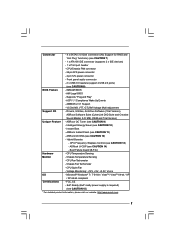
... 2 x IDE devices) - 1 x Print port header - CPU Temperature Sensing Monitor - Connector - 4 x SATAII 3.0 Gb/s connectors (No Support for RAID and "Hot Plug" functions) (see CAUTION 11) - ASRock U-COP (see CAUTION 9) - Voltage Monitoring: +12V, +5V, +3.3V, Vcore OS -...http://www.asrock.com 7 CPU Quiet Fan - Front panel audio connector - 2 x USB 2.0 headers (support 4 USB 2.0 ports) (see CAUTION 12) - AMBIOS 2.3.1 Support - CPU/Chassis FAN connector - 24 pin ATX power connector - 4 pin 12V power connector - AMI Legal BIOS - Instant Boot - ASRock OC ...
... 2 x IDE devices) - 1 x Print port header - CPU Temperature Sensing Monitor - Connector - 4 x SATAII 3.0 Gb/s connectors (No Support for RAID and "Hot Plug" functions) (see CAUTION 11) - ASRock U-COP (see CAUTION 9) - Voltage Monitoring: +12V, +5V, +3.3V, Vcore OS -...http://www.asrock.com 7 CPU Quiet Fan - Front panel audio connector - 2 x USB 2.0 headers (support 4 USB 2.0 ports) (see CAUTION 12) - AMBIOS 2.3.1 Support - CPU/Chassis FAN connector - 24 pin ATX power connector - 4 pin 12V power connector - AMI Legal BIOS - Instant Boot - ASRock OC ...

User Manual
Page 10
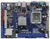
...(PCIE1) 10 Primary SATAII Connector (SATAII_1; Red) 25 Print Port Header (LPT1, Purple) 13 Fourth SATAII Connector (SATAII_4; Red) 26 FSB1 Jumper 10 Red) 24 Front Panel Audio Header 11 Secondary SATAII Connector (SATAII_2; 1.3 Motherboard Layout (G41M-VGS3 / G41M-VS3) 1 23 4 5...10 9 1 PS2_USB_PWR1 Jumper 14 Chassis Speaker Header (SPEAKER 1, Purple) 2 ATX 12V Connector (ATX12V2) 15 USB 2.0 Header (USB4_5, Blue) 3 CPU Fan Connector (CPU_FAN1) 16 Chassis Fan Connector (CHA_FAN1) 4 ATX Power Connector (ATXPWR1) 17 USB 2.0 Header (USB6_7, Blue) 5 2 x 240-pin DDR3 ...
...(PCIE1) 10 Primary SATAII Connector (SATAII_1; Red) 25 Print Port Header (LPT1, Purple) 13 Fourth SATAII Connector (SATAII_4; Red) 26 FSB1 Jumper 10 Red) 24 Front Panel Audio Header 11 Secondary SATAII Connector (SATAII_2; 1.3 Motherboard Layout (G41M-VGS3 / G41M-VS3) 1 23 4 5...10 9 1 PS2_USB_PWR1 Jumper 14 Chassis Speaker Header (SPEAKER 1, Purple) 2 ATX 12V Connector (ATX12V2) 15 USB 2.0 Header (USB4_5, Blue) 3 CPU Fan Connector (CPU_FAN1) 16 Chassis Fan Connector (CHA_FAN1) 4 ATX Power Connector (ATXPWR1) 17 USB 2.0 Header (USB6_7, Blue) 5 2 x 240-pin DDR3 ...

User Manual
Page 22
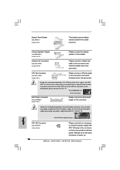
... CPU_FAN1) (see p.10 No. 16) GND +12V CHA_FAN_SPEED Please connect a chassis fan cable to this connector and match the black wire to the ground pin. System Panel Header (9-pin PANEL1) (see p.10 No. 8) Chassis Speaker Header (4-pin SPEAKER 1) (see p.10 No. 2) 22 Please note that it is necessary to connect... a power supply with ATX 12V plug to this connector so that it to Pin 1-3. If you plan...
... CPU_FAN1) (see p.10 No. 16) GND +12V CHA_FAN_SPEED Please connect a chassis fan cable to this connector and match the black wire to the ground pin. System Panel Header (9-pin PANEL1) (see p.10 No. 8) Chassis Speaker Header (4-pin SPEAKER 1) (see p.10 No. 2) 22 Please note that it is necessary to connect... a power supply with ATX 12V plug to this connector so that it to Pin 1-3. If you plan...

Quick Installation Guide
Page 2
... (PANEL1, Orange) 22 EUP LAN Jumper (EUP_LAN1) 9 IDE1 Connector (IDE1, Blue) 23 PCI Express x16 Slot (PCIE1) 10 Primary SATAII Connector (SATAII_1; Red) 26 FSB1 Jumper 2 ASRock G41M-VGS3 / G41M-VS3 Motherboard Red) (HD_AUDIO1, Lime) 12 Third SATAII Connector (SATAII_3; Red) 24 Front Panel Audio Header 11 Secondary SATAII Connector (SATAII_2; Red) 25 Print Port Header (LPT1, Purple) 13...
... (PANEL1, Orange) 22 EUP LAN Jumper (EUP_LAN1) 9 IDE1 Connector (IDE1, Blue) 23 PCI Express x16 Slot (PCIE1) 10 Primary SATAII Connector (SATAII_1; Red) 26 FSB1 Jumper 2 ASRock G41M-VGS3 / G41M-VS3 Motherboard Red) (HD_AUDIO1, Lime) 12 Third SATAII Connector (SATAII_3; Red) 24 Front Panel Audio Header 11 Secondary SATAII Connector (SATAII_2; Red) 25 Print Port Header (LPT1, Purple) 13...

Quick Installation Guide
Page 7
... Control (see CAUTION 8) BIOS Feature - 8Mb AMI BIOS - Front panel audio connector - 2 x USB 2.0 headers (support 4 USB 2.0 ports) (see CAUTION 13) - Supports "Plug and Play" - ASRock OC Tuner (see CAUTION 14) - ASRock U-COP (see CAUTION 9) - CPU Temperature Sensing Monitor - EuP Ready... MB) (OEM and Trial Version) Unique Feature - Instant Boot - ASRock OC DNA (see CAUTION 15) * For detailed product information, please visit our website: http://www.asrock.com English 7 ASRock G41M-VGS3 / G41M-VS3 Motherboard Voltage Monitoring: +12V, +5V, +3.3V, Vcore OS - ...
... Control (see CAUTION 8) BIOS Feature - 8Mb AMI BIOS - Front panel audio connector - 2 x USB 2.0 headers (support 4 USB 2.0 ports) (see CAUTION 13) - Supports "Plug and Play" - ASRock OC Tuner (see CAUTION 14) - ASRock U-COP (see CAUTION 9) - CPU Temperature Sensing Monitor - EuP Ready... MB) (OEM and Trial Version) Unique Feature - Instant Boot - ASRock OC DNA (see CAUTION 15) * For detailed product information, please visit our website: http://www.asrock.com English 7 ASRock G41M-VGS3 / G41M-VS3 Motherboard Voltage Monitoring: +12V, +5V, +3.3V, Vcore OS - ...
Quick Installation Guide
Page 18
...12 Please connect an ATX power 13 supply to this connector. 1 Though this motherboard provides 24-pin ATX power connector, it can provides sufficient power. Failing to do so will cause the failure to power up. 18 ASRock G41M-VGS3 / G41M-VS3 Motherboard English To use the 20-pin ATX power ...supply, please plug your power supply along with ATX 12V plug to this connector so that it to Pin 1-3. CPU Fan Connector (4-pin CPU_FAN1) (see p.2 No. 8) This header accommodates several system front panel functions...
...12 Please connect an ATX power 13 supply to this connector. 1 Though this motherboard provides 24-pin ATX power connector, it can provides sufficient power. Failing to do so will cause the failure to power up. 18 ASRock G41M-VGS3 / G41M-VS3 Motherboard English To use the 20-pin ATX power ...supply, please plug your power supply along with ATX 12V plug to this connector so that it to Pin 1-3. CPU Fan Connector (4-pin CPU_FAN1) (see p.2 No. 8) This header accommodates several system front panel functions...


