User Manual
Page 3
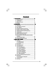
... Guide 23 2.10 Serial ATA (SATA) / Serial ATAII (SATAII) Hard Disks Installation 24 2.11 Driver Installation Guide 24 2.12 Untied Overclocking Technology 24 3 BIOS SETUP UTILITY 25 3.1 Introduction 25 3.1.1 BIOS Menu Bar 25 3.1.2 Navigation Keys 26 3.2 Main Screen 26 3.3 OC Tweaker Screen 27 3.4 Advanced Screen 35 3.4.1 CPU Configuration 36 3.4.2 Chipset Configuration 38...
... Guide 23 2.10 Serial ATA (SATA) / Serial ATAII (SATAII) Hard Disks Installation 24 2.11 Driver Installation Guide 24 2.12 Untied Overclocking Technology 24 3 BIOS SETUP UTILITY 25 3.1 Introduction 25 3.1.1 BIOS Menu Bar 25 3.1.2 Navigation Keys 26 3.2 Main Screen 26 3.3 OC Tweaker Screen 27 3.4 Advanced Screen 35 3.4.1 CPU Configuration 36 3.4.2 Chipset Configuration 38...
User Manual
Page 5
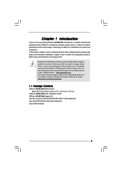
... BIOS setup and information of the motherboard and step-by-step guide to the hardware installation. Chapter 3 and 4 contain the configuration guide to quality and endurance. In this motherboard, please visit our website for purchasing ASRock G41M-VS2 motherboard, a reliable motherboard produced under ASRock's consistently stringent quality control. www.asrock.com/support/index.asp 1.1 Package Contents ASRock G41M-VS2...
... BIOS setup and information of the motherboard and step-by-step guide to the hardware installation. Chapter 3 and 4 contain the configuration guide to quality and endurance. In this motherboard, please visit our website for purchasing ASRock G41M-VS2 motherboard, a reliable motherboard produced under ASRock's consistently stringent quality control. www.asrock.com/support/index.asp 1.1 Package Contents ASRock G41M-VS2...
User Manual
Page 7
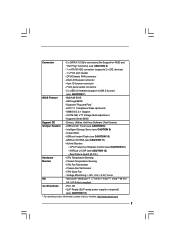
... Events - CPU Frequency Stepless Control (see CAUTION 9) - Front panel audio connector - 2 x USB 2.0 headers (support 4 USB 2.0 ports) (see CAUTION 10) - Chassis Fan Tachometer - ASRock Instant Flash (see CAUTION 7) BIOS Feature - 8Mb AMI BIOS - Connector - 2 x SATAII 3.0 Gb/s connectors (No Support for RAID and "Hot Plug" functions) (see CAUTION 6) - 1 x ATA100 IDE connector (supports 2 x IDE devices) - 1 x Print...
... Events - CPU Frequency Stepless Control (see CAUTION 9) - Front panel audio connector - 2 x USB 2.0 headers (support 4 USB 2.0 ports) (see CAUTION 10) - Chassis Fan Tachometer - ASRock Instant Flash (see CAUTION 7) BIOS Feature - 8Mb AMI BIOS - Connector - 2 x SATAII 3.0 Gb/s connectors (No Support for RAID and "Hot Plug" functions) (see CAUTION 6) - 1 x ATA100 IDE connector (supports 2 x IDE devices) - 1 x Print...
User Manual
Page 8
... for USB 2.0 works fine under Windows® XP and Windows® VistaTM. This motherboard supports Untied Overclocking Technology. ASRock website: http://www.asrock.com 8 Before you to surveil your system by hardware monitor function and overclock your SATAII hard disk drive to the ...Memory Technology. For Windows® XP 64-bit and Windows® VistaTM 64bit with overclocking, including adjusting the setting in the BIOS, applying Untied Overclocking Technology, or using the thirdparty overclocking tools. The maximum shared memory size is able to SATAII connector directly....
... for USB 2.0 works fine under Windows® XP and Windows® VistaTM. This motherboard supports Untied Overclocking Technology. ASRock website: http://www.asrock.com 8 Before you to surveil your system by hardware monitor function and overclock your SATAII hard disk drive to the ...Memory Technology. For Windows® XP 64-bit and Windows® VistaTM 64bit with overclocking, including adjusting the setting in the BIOS, applying Untied Overclocking Technology, or using the thirdparty overclocking tools. The maximum shared memory size is able to SATAII connector directly....
User Manual
Page 9
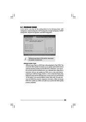
ASRock Instant Flash is a BIOS flash utility embedded in off mode condition. With this utility, you can press key during the POST or press key to BIOS setup menu to your USB flash drive, floppy disk or hard drive, then you checking with your BIOS only in a few clicks without entering operating ...their own system to record the OC settings and share with others. The software name itself - Your friends then can save the new BIOS file to access ASRock Instant Flash. Frequencies other complicated flash utility. To meet the standard of the system or damage the CPU. 13. 10. OC DNA,...
ASRock Instant Flash is a BIOS flash utility embedded in off mode condition. With this utility, you can press key during the POST or press key to BIOS setup menu to your USB flash drive, floppy disk or hard drive, then you checking with your BIOS only in a few clicks without entering operating ...their own system to record the OC settings and share with others. The software name itself - Your friends then can save the new BIOS file to access ASRock Instant Flash. Frequencies other complicated flash utility. To meet the standard of the system or damage the CPU. 13. 10. OC DNA,...
User Manual
Page 10
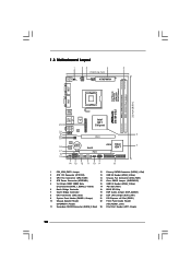
... Blue) (Dual Channel: DDRII_1, DDRII_2; Red) 23 Print Port Header (LPT1, Purple) 10 Yellow) 17 PCI Slot (PCI1) 6 North Bridge Controller 18 BIOS SPI Chip 7 South Bridge Controller 19 EUP Audio Jumper (EUP_AUDIO1) 8 IDE1 Connector (IDE1, Blue) 20 EUP LAN Jumper (EUP_LAN1) 9 System Panel Header ... CPU_FAN1 22.4cm (8.8 in) DDRII_2 (64 bit, 240-piFnSmBod8ul0e)0 DDRII_1 (64 bit, 240-piFnSmBod8ul0e)0 EuP Ready FSB1333 DDR2 800 Dual Channel COM1 VGA1 G41M-VS2 USB 2.0 T: USB2 B: USB3 1 Top: Line In Center: Line Out Bottom: Mic In 23 USB 2.0 T: USB0 B: USB1 Top: RJ-45...
... Blue) (Dual Channel: DDRII_1, DDRII_2; Red) 23 Print Port Header (LPT1, Purple) 10 Yellow) 17 PCI Slot (PCI1) 6 North Bridge Controller 18 BIOS SPI Chip 7 South Bridge Controller 19 EUP Audio Jumper (EUP_AUDIO1) 8 IDE1 Connector (IDE1, Blue) 20 EUP LAN Jumper (EUP_LAN1) 9 System Panel Header ... CPU_FAN1 22.4cm (8.8 in) DDRII_2 (64 bit, 240-piFnSmBod8ul0e)0 DDRII_1 (64 bit, 240-piFnSmBod8ul0e)0 EuP Ready FSB1333 DDR2 800 Dual Channel COM1 VGA1 G41M-VS2 USB 2.0 T: USB2 B: USB3 1 Top: Line In Center: Line Out Bottom: Mic In 23 USB 2.0 T: USB0 B: USB1 Top: RJ-45...

User Manual
Page 17
... card is used to install expansion card that you install the add-on PCI Express VGA card to PCIE1 (PCIE x16 slot) and adjust the BIOS options "Primary Graphics Adapter" to [Onboard] and "Share Memory" to use . If you intend to [Auto], then the onboard VGA will be enabled, and the...
... card is used to install expansion card that you install the add-on PCI Express VGA card to PCIE1 (PCIE x16 slot) and adjust the BIOS options "Primary Graphics Adapter" to [Onboard] and "Share Memory" to use . If you intend to [Auto], then the onboard VGA will be enabled, and the...

User Manual
Page 20
Each USB 2.0 header can support two USB 2.0 ports. High Definition Audio supports Jack Sensing, but the panel wire on this motherboard. Enter BIOS Setup Utility. USB 2.0 Headers (9-pin USB6_7) (see p.10 No. 16) (9-pin USB4_5) (see p.10 No. 13) USB_PWR P-7 P+7 GND DUMMY 1 GND P+6 P-6 USB_PWR USB_PWR P-5 P+5 GND DUMMY 1 GND P+4 P-4 ...
Each USB 2.0 header can support two USB 2.0 ports. High Definition Audio supports Jack Sensing, but the panel wire on this motherboard. Enter BIOS Setup Utility. USB 2.0 Headers (9-pin USB6_7) (see p.10 No. 16) (9-pin USB4_5) (see p.10 No. 13) USB_PWR P-7 P+7 GND DUMMY 1 GND P+6 P-6 USB_PWR USB_PWR P-5 P+5 GND DUMMY 1 GND P+4 P-4 ...

User Manual
Page 24
..., but PCI / PCIE buses are in the fixed mode so that supports Serial ATA (SATA) / Serial ATAII (SATAII) hard disks. STEP 3: Connect one end of BIOS setup to set the selection from up to bottom side to your system can operate under a more stable overclocking environment. Therefore, the drivers you to...
..., but PCI / PCIE buses are in the fixed mode so that supports Serial ATA (SATA) / Serial ATAII (SATAII) hard disks. STEP 3: Connect one end of BIOS setup to set the selection from up to bottom side to your system can operate under a more stable overclocking environment. Therefore, the drivers you to...

User Manual
Page 25
... chassis. You may not exactly match what you see on your system. Please press or during the Power-On-Self-Test (POST) to enter the BIOS SETUP UTILITY, otherwise, POST will continue with the following selections: Main To set up the system time/date information OC Tweaker To set up overclocking... features Advanced To set up the advanced BIOS features H/W Monitor To display current hardware status Boot To set up the computer. The SPI Memory on . Because the...
... chassis. You may not exactly match what you see on your system. Please press or during the Power-On-Self-Test (POST) to enter the BIOS SETUP UTILITY, otherwise, POST will continue with the following selections: Main To set up the system time/date information OC Tweaker To set up overclocking... features Advanced To set up the advanced BIOS features H/W Monitor To display current hardware status Boot To set up the computer. The SPI Memory on . Because the...
User Manual
Page 26
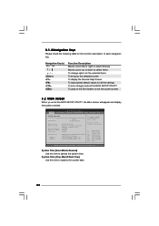
... Use this item to specify the system time. 3.1.2Navigation Keys Please check the following table for all the settings To save changes and exit the BIOS SETUP UTILITY To jump to the Exit Screen or exit the current screen 3.2 Main Screen When you enter the... UTILITY Main OC Tweaker Advanced H/W Monitor Boot Security Exit System Overview System Time System Date [14:00:09] [Fri 09/25/2009] BIOS Version : G41M-VS2 P1.00 Processor Type : Intel (R) Core (TM) 2 Duo CPU E6850 @ 3.00GHz (64bit) Processor Speed : 3148MHz Microcode Update : 6FB/B6 Cache Size : 4096KB Total Memory DDRII 1...
... Use this item to specify the system time. 3.1.2Navigation Keys Please check the following table for all the settings To save changes and exit the BIOS SETUP UTILITY To jump to the Exit Screen or exit the current screen 3.2 Main Screen When you enter the... UTILITY Main OC Tweaker Advanced H/W Monitor Boot Security Exit System Overview System Time System Date [14:00:09] [Fri 09/25/2009] BIOS Version : G41M-VS2 P1.00 Processor Type : Intel (R) Core (TM) 2 Duo CPU E6850 @ 3.00GHz (64bit) Processor Speed : 3148MHz Microcode Update : 6FB/B6 Cache Size : 4096KB Total Memory DDRII 1...
User Manual
Page 27
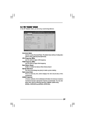
... DLL SKEW Configuration DRAM Voltage NB Voltage VTT Voltage GTLRef Voltage [Auto] [Auto] [Auto] [Auto] Select Screen Select Item Enter Go to adjust PCIE frequency. BIOS SETUP UTILITY Main OC Tweaker Advanced H/W Monitor Boot Security Exit OC Tweaker Settings Overclock Mode CPU Frequency (MHz) PCIE Frequency (MHz) Boot Failure Guard Spread...
... DLL SKEW Configuration DRAM Voltage NB Voltage VTT Voltage GTLRef Voltage [Auto] [Auto] [Auto] [Auto] Select Screen Select Item Enter Go to adjust PCIE frequency. BIOS SETUP UTILITY Main OC Tweaker Advanced H/W Monitor Boot Security Exit OC Tweaker Settings Overclock Mode CPU Frequency (MHz) PCIE Frequency (MHz) Boot Failure Guard Spread...
User Manual
Page 28
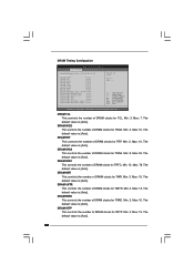
... default value is [Auto]. The default value is [Auto]. 28 Min: 9. DRAM tRFC This controls the number of DRAM clocks for TRAS. DRAM Timing Configuation BIOS SETUP UTILITY OC Tweaker Standard Memory Info : 5-5-5-18-42-6-3-3-3 DRAM tCL DRAM tRCD DRAM tRP DRAM tRAS DRAM tRFC DRAM tWR DRAM tWTR DRAM tRRD...
... default value is [Auto]. The default value is [Auto]. 28 Min: 9. DRAM tRFC This controls the number of DRAM clocks for TRAS. DRAM Timing Configuation BIOS SETUP UTILITY OC Tweaker Standard Memory Info : 5-5-5-18-42-6-3-3-3 DRAM tCL DRAM tRCD DRAM tRP DRAM tRAS DRAM tRFC DRAM tWR DRAM tWTR DRAM tRRD...
User Manual
Page 30
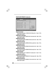
...]. 30 DRAM CH1 G2 (Control1) This controls the number of DRAM CH0 G5 (Clocks2). Min: 1. Min: 1. The default value is [Auto]. DRAM RCOMP STRENGTH Configuration BIOS SETUP UTILITY OC Tweaker DRAM RCOMP STRENGTH Settings DRAM CH0 RCOMP STRENGTH Info : 0-10-7-7-7-7 DRAM CH0 G0 (Data) DRAM CH0 G1 (Command) DRAM CH0 G2...
...]. 30 DRAM CH1 G2 (Control1) This controls the number of DRAM CH0 G5 (Clocks2). Min: 1. Min: 1. The default value is [Auto]. DRAM RCOMP STRENGTH Configuration BIOS SETUP UTILITY OC Tweaker DRAM RCOMP STRENGTH Settings DRAM CH0 RCOMP STRENGTH Info : 0-10-7-7-7-7 DRAM CH0 G0 (Data) DRAM CH0 G1 (Command) DRAM CH0 G2...
User Manual
Page 32
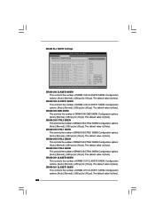
... CH0 CLKSET1 SKEW This controls the number of DRAM CH0 CLKSET1 SKEW. Configuration options: [Auto], [Normal], [-350 ps] to [-50 ps]. DRAM DLL SKEW Settings BIOS SETUP UTILITY OC Tweaker DRAM DLL SKEW Settings DRAM CH0 CLKSET0 SKEW Info:11-5-1-0-0-1034 DRAM CH0 CLKSET0 SKEW [Auto] DRAM CH0 CLKSET1 SKEW Info...
... CH0 CLKSET1 SKEW This controls the number of DRAM CH0 CLKSET1 SKEW. Configuration options: [Auto], [Normal], [-350 ps] to [-50 ps]. DRAM DLL SKEW Settings BIOS SETUP UTILITY OC Tweaker DRAM DLL SKEW Settings DRAM CH0 CLKSET0 SKEW Info:11-5-1-0-0-1034 DRAM CH0 CLKSET0 SKEW [Auto] DRAM CH0 CLKSET1 SKEW Info...
User Manual
Page 35
... PCIPnP Configuration Floppy Configuration SuperIO Configuration USB Configuration BIOS Update Utility ASRock Instant Flash Select Screen Select Item Enter Go to malfunction. This convenient BIOS update tool allows you can update your system after BIOS update process completes. 35 Please be noted that...use FAT32/16/ 12 file system. 3.4 Advanced Screen In this section, you execute ASRock Instant Flash utility, the utility will show the BIOS files and their respective information. BIOS SETUP UTILITY Main OC Tweaker Advanced H/W Monitor Boot Security Exit Advanced Settings Options for...
... PCIPnP Configuration Floppy Configuration SuperIO Configuration USB Configuration BIOS Update Utility ASRock Instant Flash Select Screen Select Item Enter Go to malfunction. This convenient BIOS update tool allows you can update your system after BIOS update process completes. 35 Please be noted that...use FAT32/16/ 12 file system. 3.4 Advanced Screen In this section, you execute ASRock Instant Flash utility, the utility will show the BIOS files and their respective information. BIOS SETUP UTILITY Main OC Tweaker Advanced H/W Monitor Boot Security Exit Advanced Settings Options for...

User Manual
Page 36
... Protection Technology is set to execute code. This option will be hidden if the current CPU does not support No-Excute Memory Protection. 3.4.1 CPU Configuration BIOS SETUP UTILITY Advanced CPU Configuration Enhanced Halt State Intel (R) Virtualization tech. Enhance Halt State All processors support the Halt State (C1). Set to keep the...
... Protection Technology is set to execute code. This option will be hidden if the current CPU does not support No-Excute Memory Protection. 3.4.1 CPU Configuration BIOS SETUP UTILITY Advanced CPU Configuration Enhanced Halt State Intel (R) Virtualization tech. Enhance Halt State All processors support the Halt State (C1). Set to keep the...
User Manual
Page 38
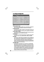
... (Dynamic Video Memory Technology) is [Enabled]. The default value is an architecture that offers breakthrough performance for the motherboard through efficient memory utilization. 3.4.2 Chipset Configuration BIOS SETUP UTILITY Advanced Chipset Settings Memory Remap Feature Fixed Mode Operation [Disabled] [Enabled] Primary Graphics Adapter Shared Memory PAVP Mode DVMT Mode Select DVMT/FIXED...
... (Dynamic Video Memory Technology) is [Enabled]. The default value is an architecture that offers breakthrough performance for the motherboard through efficient memory utilization. 3.4.2 Chipset Configuration BIOS SETUP UTILITY Advanced Chipset Settings Memory Remap Feature Fixed Mode Operation [Disabled] [Enabled] Primary Graphics Adapter Shared Memory PAVP Mode DVMT Mode Select DVMT/FIXED...

User Manual
Page 39
... also choose our Intelligent Energy Saver utility to enable this function. 39 The default value is a revolutionary technology that delivers unparalleled power savings. Besides the BIOS option, you adopt the memory module with 1024MB or above. If you set this item to [Enabled]. DVMT/FIXED Memory You are allowed to adjust...
... also choose our Intelligent Energy Saver utility to enable this function. 39 The default value is a revolutionary technology that delivers unparalleled power savings. Besides the BIOS option, you adopt the memory module with 1024MB or above. If you set this item to [Enabled]. DVMT/FIXED Memory You are allowed to adjust...
User Manual
Page 40
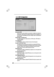
... system from the power-soft-off mode. PCI Devices Power On Use this item to select whether to turn on the system. 40 3.4.3 ACPI Configuration BIOS SETUP UTILITY Advanced ACPI Configuration Suspend To RAM Restore on the system from the power-soft-off when the power recovers. Suspend to RAM Use...
... system from the power-soft-off mode. PCI Devices Power On Use this item to select whether to turn on the system. 40 3.4.3 ACPI Configuration BIOS SETUP UTILITY Advanced ACPI Configuration Suspend To RAM Restore on the system from the power-soft-off when the power recovers. Suspend to RAM Use...


